Automatic gain control is necessary in communications receivers because of the wide variations in signal strength encountered at the antenna terminal. While small signals require more amplification in the i-f to produce the same audible output as the stronger signals, the opposite is true in the case of very strong signals. The agc mechanism is intended to follow these variations and properly compensate for them, so that the audible output will remain nearly constant.
The process is further complicated by rapid fading, accommodating for different modes and rates of transmissions, and suppressing the effects of a adjacent channel interference and noise. The agc can be viewed as a control loop as shown in Fig. 1.
Its performance characteristics are based on control system theory similar to that presented earlier. The difference is that instead of a phase/frequency-correcting mechanism it uses a gain-correcting mechanism. In a system such as the one in Fig. 1 the relative change in output voltage (expressed in millivolts) is proportional to the logarithm of the relative input voltage change (expressed in decibels). This often forgotten fact is usually the missing link in understanding simple automatic gain control systems.
On the practical side, the control voltage produced by the agc system must be applied rapidly to the gain stages at the beginning of each message element received. For receiving a single-sideband signal, a 2 millisecond risetime would be sufficient to overcome any thumping tendency at the beginning of a word. The release requirement is much longer (2 to 3 seconds). The fast-attack slow-release concept has been used extensively by the manufacturers, but the delay timing requirements have been disputed by operators. As a generality, typical circuits having attack times ranging from 2 to 200 milliseconds and release times ranging from 0.5 to 3 seconds have been used extensively.
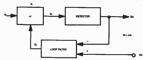
Fig. 1. Agc loop.
I-F DERIVED AGC
The i-f derived agc obtains its information at the output of the last i-f stage, usually through a simple diode detector. The averaged dc voltage obtained here is further amplified and applied to all the gain stages in the i-f amplifier, reducing the gain as necessary. Most communications receivers today use i-f-derived agc.
Figure 2 shows a practical implementation of an i-f-derived agc as applied to the 9 MHz i-f example communications receiver. The i-f output is detected and applied to a dc amplifier at Q2 which in turn controls the gain of the MC 1590's. The time constants are determined by C1 and C2.
AUDIO-DERIVED AGC
Another type of age is the audio-derived. In this approach the correction voltage necessary to control the gain in the i-f stages is obtained from the audio section of the receiver. The rectified voltage is further amplified and applied to the gain stages of the i-f amplifier much the same way as in the i-f-derived agc.
This method of agc is not very popular in communications receivers because of its relatively poor performance. The narrow bandwidths of the signal at this point in a receiver does not allow for millisecond rise-times, further more in-band intermodulation distortion created in the i-f stages contributes to a phenomenon called "pumping" which is undesirable.
"HANGED" AGC
In a typical agc system, the release time depends on the discharge of a capacitor. Although this is a desired function for SSB or cw reception, the false alarm caused by a noise burst will deactivate the receiver for an unnecessary amount of time, thus the "hanged" age was created. The "hanged" agc is designed to change the time constants and compensate for noise bursts, while still maintaining the characteristics of the fast-attack slow-release agc for SSB and cw signals. This type of agc can also be viewed as a noise discriminator. Such design usually involves i-f as well as audio-derived agc systems.

Fig. 2. Implementation of an i-f-derived agc.

Fig. 3. PIN diode agc.
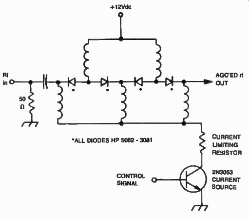
Fig. 4. An rf agc using four PIN diodes.
THE PIN DIODE ATTENUATOR USED FOR AGC
It is possible to apply agc to the front end of a communications receiver, providing attenuation directly at the antenna. This technique is used successfully to prevent front end overload, considerably reducing intermodulation distortion in this stage. This is accomplished by using a PIN diode attenuator which is used in series with the antenna terminal. The PIN diode will conduct rf only i-f biased properly. Figure 3 shows an actual implementation of an audio-derived agc which controls a PIN attenuator, as applied to the 9 MHz i-f model receiver. In this example the audio signal is amplified by U1 and Q1 and detected by diodes D1 and D2.
This agc signal is further buffered by Q2 and fed to the base of a current source transistor Q3. The PIN diode is biased forward from the +12 volt supply. The current will flow through the diode to ground as controlled by the current source transistor Q3 and the current-limiting resistor RL (100mA max), allowing variable attenuation to be achieved at the antenna input. As much as 40 dB of attenuation can be obtained with this approach. A ladder network of several PIN diodes could be substituted for the single diode providing a greater range of attenuation. Transistor Q3 is capable of a continuous collector current of 700 mA and should be heat-sunk if such of installation is contemplated. Figure 4 shows a four PIN diode attenuator using the HP-5082-3081. Also, see Fig. 5 and Table 1.
This approach can provide as much as 80 dB of attenuation, but greater attenuation can not be achieved because of the physical layout which make the "wrap around" leakage phenomenon the limiting factor. PIN diode attenuators can also be used in i-f chains in order to improve upon existing conventional agc's. The technique is, however, somewhat reluctantly used because of the possible intermodulation distortion which it might create.
Table 1. Specifications of the HF -1030 Communications Receiver.
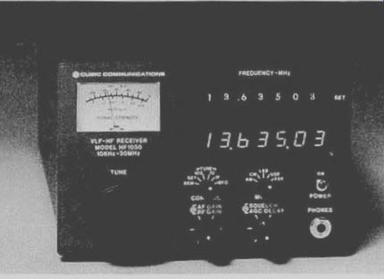
Fig. 5. Model HF-1030 general coverage communications receiver features
a fast switching synthesizer (25 msec switching/settling speed) with
a resolution of 10 Hz. The intercept point is + 20 dBm (courtesy of Cubic
Communications).
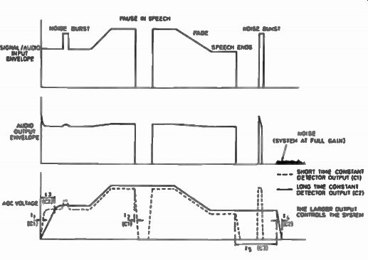
Fig. 6. Performance of the Plessey SL 621 IC.
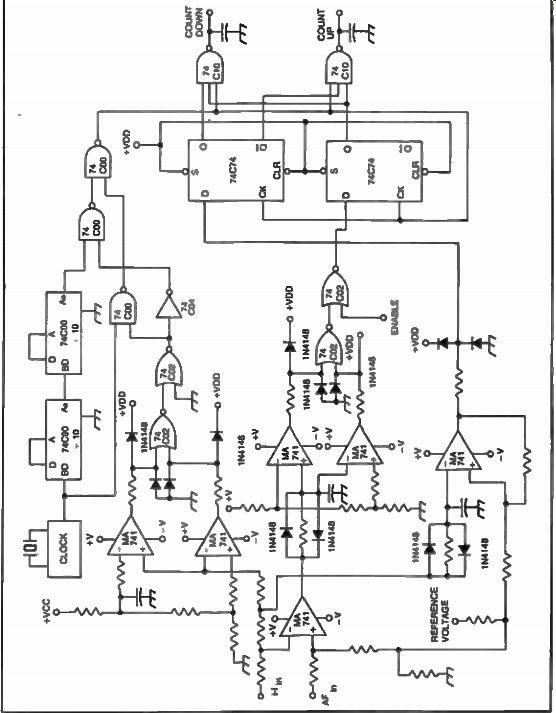
Fig. 7
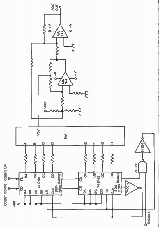
Fig. 8
SPECIAL AGC's
Another interesting agc method is provided by the rather unusual Plessey, SL 621 IC. This agc generator combines an audio amplifier and two peak detectors with two different time constants, one short and one long. A careful choice of these values will allow the desired independent selection of the attack, hold, and release times. Because of its special design, this system will ignore a noise burst, but will follow a rapidly fading signal, as well as maintain the same agc level for a pause in speech. The performance of the Plessey SL 621 agc generator is shown in Fig. 6. It can be seen from this figure that the detector with the larger output controls the system. Therefore, if a noise burst was received during speech the long time-constant detector output will dominate, and the noise burst will be ignored. The short time-constant detector will only be activated by the noise burst providing short agc signals, thus contributing to the cancellation. Although the SL 621 is an audio-derived agc system, it qualifies as a "hanged" agc by definition.
DIGITAL AGC's
Another age method which is relatively unknown is the digital age. An implementation is shown in Figs. 7 and 8. In this approach, the age output is a function of an eight-bit digital number which is present at the binary inputs of the digital-to-analog converter. This number is continuously changing, and reflects the counting state of two cascaded up/down counters (74C193) at any given time. If a clock was fed to the counters and the count-up command is activated, the age voltage at the output of the digital-to-analog converter will increase with every count until reaching the maximum voltage allowed by the number of bits. It is evident that the attack time of this voltage is directly proportional to the frequency of the clock.
The higher this frequency is, the faster the maximum digital number (and therefore the maximum age voltage) is reached.
If the count-down line is activated on the up/down counters, and the clock was slowed down, a reduction in the age voltage will be accomplished, but this time at a slower rate than it went up. The attack and release times can then be programmed at will by merely changing between two clock speeds when selecting between the count-up and the count-down modes.
The two frequencies are usually 40 Hz for the attack time (count up) and 4 Hz for the release time (count down). Signal level information from two points of interest in the receiver (usually the i-f and the audio amplifier) control the gating of the properly chosen clock frequency for the up/down counter, as well as the up or down commands.
This system can be imagined as a continuously changing counter which is going up fast and coming down slow, with the age voltage following this pattern. Because of the complex switching involved in this type of age, low-current logic should be used in the design. Our example was implemented with CMOS logic for this reason. This relatively expensive age system has the advantage of being extremely reliable. The precise programmability of the attack and release times also makes it an ideal choice for a communications receiver.