The most popular superheterodyne ever realized was a single conversion type with an i-f of 455 kHz. The block diagram in Fig. 1 shows a typical single conversion superheterodyne which tunes the frequency range from 500 kHz to 30 MHz. The i-f amplifier is tuned to 455 kHz.
The incoming signal anywhere between 500 kHz to 30 MHz passes through a tuned circuit called the preselector. The preselector. has the role of filtering out all frequencies coming from the antenna, except for the one that is needed. This filtered signal goes to the mixer, which can take several forms, where it combines with the frequency coming from the local oscillator (in our case a variable frequency oscillator) and produces an i-f signal at 455 kHz.
As you have probably noticed, this is a down-conversion scheme because the i-f falls below all of the frequencies to be received within the range of 500 kHz to 30 MHz. The Vfo is operating 455 kHz above the incoming frequency at all times. For example, if we want to receive 500 kHz, the Vfo must generate 955 kHz. And, if we want to receive 30 MHz, the Vfo should be 30.455 MHz.
As a result of the interaction between the Vio and the signal, there are two signals (referred to as products) coming out of our mixer, the sum and the difference (other products are generated as a result of the mixing and they will be reviewed later in this guide). The higher product is rejected by the i-f filter, in this case, a transformer tuned to 455 kHz.
Note that no matter where we tune the receiver, the i-f is always the same, making processing of the signal identical for all frequencies to be received. This is why the superheterodyne has lasted until our day as the best design.
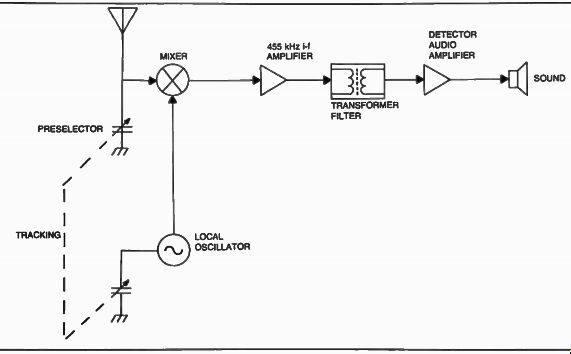
Fig. 1. General coverage single conversion superheterodyne receiver
block diagram.
The 455 kHz signal, which also contains the information that came from the antenna, is filtered and amplified in the i-f amplifier, and is finally detected and amplified again at audio frequency before being delivered to the speaker. This scheme remains, to date, a basic approach of the single conversion superheterodyne. Note the tracking mechanism of the scheme (Fig. 2). In this type of radio, it is imperative that the preselector and the Vfo track together.
In a basic single conversion hf receiver covering 500 kHz to 30 MHz, the incoming signal does not really go to just one filter preselector. Several filters are switched in and out for different ranges*, one at the time, allowing for several bands to be covered. The reason for this is that one tuned circuit cannot cover the entire range of 29.5 MHz properly. The Vfo is switched in similar bands, which exactly correspond in coverage to the preselector bands.
The tuning element of the preselector, the variable capacitor, is mechanically ganged with the Vfo capacitor, and they track together, so that when the preselector peaks at some frequency, the Vfo operates exactly 455 kHz above that frequency, as shown before. For example, if the preselector is tuned to exactly 1 MHz, it's capacitor is mechanically ganged with the Vfo capacitor, so that the Vfo produces exactly 1.455 MHz (Figs. 3 and 4). The rest of the circuitry remains the same, as described previously.
A practical receiver could be implemented as shown in the schematic diagram in Fig. 5. The signal from the antenna goes to switch S1-1 which couples it with any one of the five preselector tuned circuits, corresponding to the 5 bands in this case. Switch S1-2 which is mechanically ganged with S1-1 picks up the output of the preselector range chosen, and together with the variable capacitor which is always in the circuit, tracks the exact frequency to be received, which is exactly 455 kHz below the frequency of the Vfo.
The Vfo capacitor is mechanically coupled with the preselector capacitor. S1-3A and S1-4 are also mechanically connected with S1-1 and S1-2 in order to provide the right ranges for the Vfo to match the preselector. The Vfo signal couples through C18 into Q2 where it combines with the proper preselected signal and produces a difference frequency of exactly 455 kHz for any selected receiver frequency between 500 kHz and 30 MHz.
The signal is directed through a ceramic filter which eliminates all the unwanted mixing products and keeps only the 455 kHz signal which is routed through a chain of amplifiers, where it is detected and fed through a volume control, into an audio amplifier made of Q1, Q2, Q3, and Q4 (circuit board #2) and finally into the speaker.
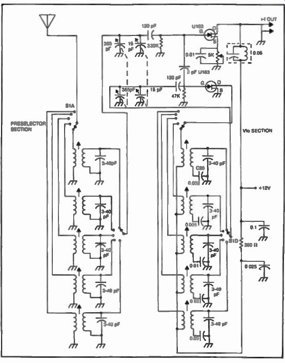
Fig. 2. Modern implementation of tracking mechanism for preselector
and variable frequency oscillator, showing band selector.
By now, some of us probably wondered why was 455 kHz the choice for the i-f? Is there anything special about this frequency? There are two reasons for this choice.
• It was right below the broadcast band.
[ 'Portion of the radio frequency spectrum designed to be received by a particular radio receiver, which for practical reasons can be broken down into "bands". ]
• It was low enough in frequency to allow adequate selectivity to be obtained with conventional inductors and capacitors (L/C). Selectivity was not really a problem in the earlier days, but became one by the 1930s when the spectrum became crowded and because of it, the main disadvantage of the 455 kHz scheme became apparent. See Figs. 6 and 7.
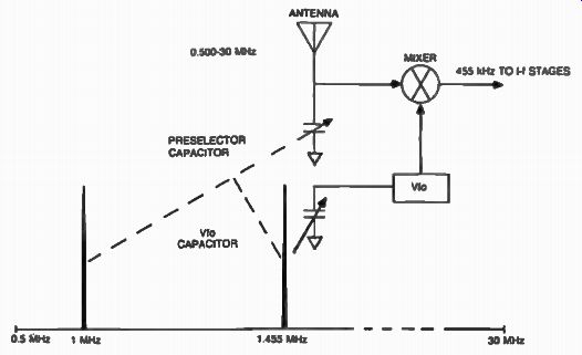
Fig. 3. Tracking mechanism of a general coverage single conversion
superheterodyne.
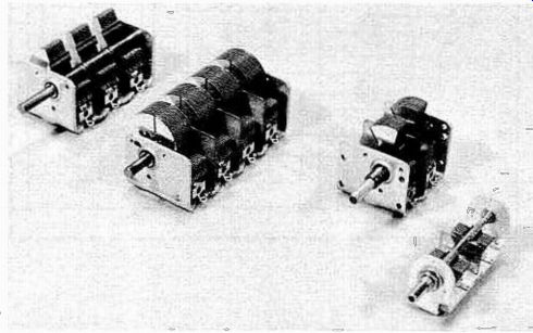
Fig. 4. Modern variable capacitors featuring as many as four tracking
sections are being used in superheterodyne receivers.
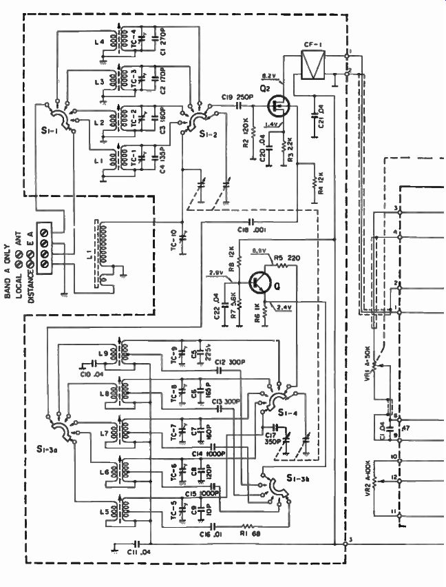
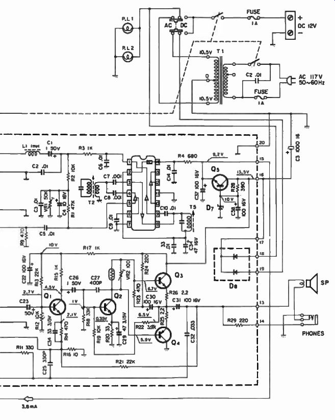
Fig. 5. Modern implementation of a general coverage 455 kHz single
conversion superheterodyne receiver.
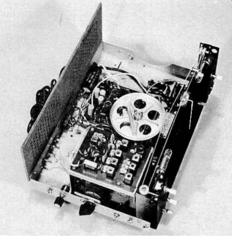
Fig. 6. The general coverage receiver showing the location of the
preselector section.
THE IMAGE PROBLEM
We were all very happy with our radios and could hear a lot of stations with our general coverage receivers. Some of these stations were one and the same (received in several places on the dials). Even though this phenomenon was discovered during the 1920s, it wasn't until the 1950s when manufacturers did something about it. Here is what the 1926 edition of the Radio News Superheterodyne Book says in regard to this problem, offering a solution: "There are many other instances where slight improvements may be made. Two straight-line frequency condensers, mounted on one shaft, for the oscillator and tuner circuits are recommended. This not only simplifies tuning, but eliminates the objectionable feature of every superheterodyne-the reception of all stations on more than one setting of the oscillator dial". This phenomenon is called image.
It has been established that the incoming signal frequency from the antenna beats with the local oscillator to produce the intermediate frequency for further amplification. This oscillator could be below or above the incoming frequency by the intermediate frequency value. Usually, the total oscillator is above the incoming frequency signal, as in our case, and it would oscillate, for example, at 14.545 MHz to convert a 14.090 MHz signal to an intermediate frequency of 455 kHz.
Another station, such as WWV at 15.000 MHz, would also mix with the 14.545 MHz local oscillator producing the 455 kHz intermediate frequency.
If the front-end selectivity of the receiver is poor, and the 15.000 MHz station is strong, it will also be heard with the receiver tuned to 14.090 MHz and interfere with a real 14.090 MHz signal.
To dramatize this, consider the case in Fig. 8. Station A broadcasts at 14.090 MHz with 100 watts of power, and Station B broadcasts at 15.000 MHz with a power of 10 kilowatts. The relatively wide preselector is set at 14.090 MHz as shown. The Vfo oscillates at 14.545 MHz. Station A combines with the Vfo producing 455 kHz and this signal is processed further in the i-f chain and amplifier and is detected and heard in the speaker.
Station B at 15.000 MHz, falls within the pass band of the preselector, although somewhat attenuated by it. The preselector is of the type discussed previously. It involves one or two tuned circuits, and Station B is powerful enough to make up for the off-frequency rejection as shown in our exaggerated case here. Station B at 15.000 MHz also mixes with the 14.545 MHz oscillator producing the 455 kHz i-f signal which is processed along with the signal from Station A and is heard at the same time, thus interfering with the real signal.
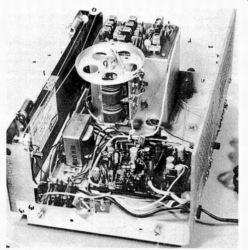
Fig. 7. Overall view of the 455 kHz i-f general coverage receiver
showing the vfo capacitor mechanically coupled with the preselector capacitor.
The image is twice the intermediate frequency above the received signal if the oscillator frequency is above the desired signal frequency, or twice the intermediate frequency below the signal frequency if the oscillator is below the desired signal frequency. We can then say that in a typical 455 kHz receiver, images will be created by any stations 910 kHz above the frequency being received.
In such a system, a strong station from one end of the 28 MHz amateur band can interfere with the reception of a weak station at the other end.
Most images are caused by other than amateur signals, and can be quite strong, presenting a great problem if such a receiver would be used aboard a military ship or aircraft, where as many as thirty or more transmitters could be operating in close physical proximity.
Improving preselector selectivity would mean increasing the number of tuned circuits with additional complex mechanical switching. The complexity of such an arrangement is exemplified by Fig. 9 which shows the schematic diagram of an actual implementation of two-pole preselector and local oscillator in the Realistic DX-160 communications receiver. This arrangement provides an image rejection from -20 dB to -65 dB below the station being received, depending on the band of interest (measurements were made in the center of the bands). Some attempts have been made to minimize the switching of multipole preselectors by using combinations of variable capacitors with very wide range, with magnetically or electromagnetically tuned ferrite coils. Figure 4-10 shows a list of such products made by Vani-L Corp. It is known that a ferrite coil changes its inductance characteristics over a wide range in the presence of a magnetic field. This phenomena is exploited in these products by applying a dc current bias to an electromagnet facing the main coil which is wound on a ferrite core as shown in Fig. 11. Changing this bias changes the inductance of the particular coil, providing the designer with a means of extending the preselected range with minimum switching. See Figs. 12 and 13.
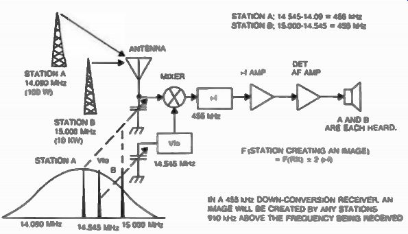
Fig. 8. The image in a455 kHz i-f single conversion superheterodyne
receiver.
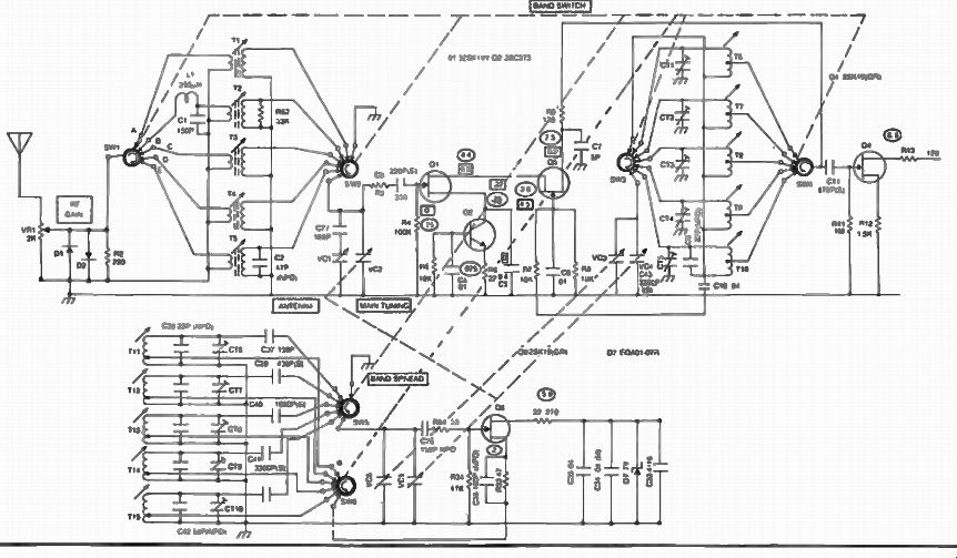
Fig. 9
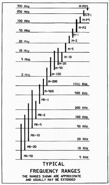
Fig. 10. Typical frequency ranges of electrically variable inductors.
The ranges shown are approximate and usually may be extended (courtesy
of Van-L Corporation).

Fig. 11. Cut-away of a Vani-L inductor (courtesy of Vani-L Corporation).
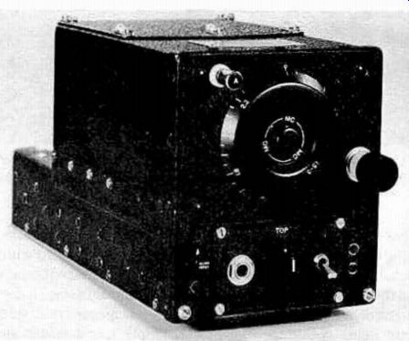
Fig. 12. This aircraft radio receiver is typical of the ARC-5/BC type.
Several such receivers were used in order to cover a greater range of
frequencies.
This property was further developed in a preselector that uses opposing polarity magnets with a toroidal ferrite coil sandwiched between them as shown in Fig. 14 and Fig. 15. A set of four magnets polarized as shown are the stator of the device, while another set of four magnets are mounted in the rotor. The ferrite toroidal coil is mounted between the stator and rotor and forms the first pole of the preselector.
The second pole is made of another toroidal ferrite coil which is identical with the first one and is mounted on the other side of the rotor, which is now common to both poles. A third set of magnets polarized the same way as the first part of the stator completes the arrangement.
The specially-arranged magnetic field created by the rotor can then permeability-tune both toroidal ferrite coils proportionally, making for an extremely wide tuning non-switching preselector. The number of poles could be increased providing for sharper response.
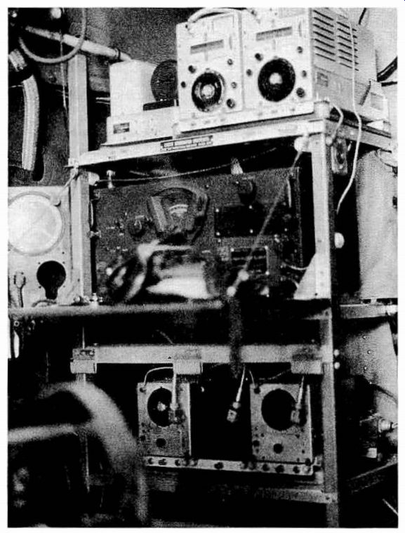
Fig. 13. ARC-5 receivers used in the cockpit of an aircraft during
WWII (Photo taken by Roger Musolf at the National Air and Space Museum,
Washington, D.C.).
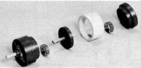
Fig. 14. A two-pole permeability tuned preselector.
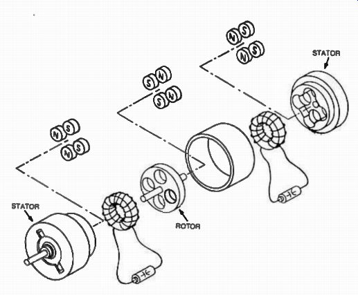
Fig. 15. A mechanical arrangement of parts in the permeability-tuned
preselector.
This preselector was designed to cover from 0.5 to 30 MHz by only switching the capacitors across once. Several problems occur with such an approach, however. Too much magnetic field will drive ferrites into saturation and the point of saturation is not always predictable since it depends on temperature. Secondly, unless the preselector is magnetically shielded, ac magnetic fields resulting from power supply transformers and other sources can easily modulate the ferrite coils. In reality, this preselector would become impractical. The real fix for suppressing the image problem is to choose the i-f at a much higher frequency. Mathematically, this proves to be preferred.
If the frequency of a strong station creating an image equals F(R)O + 2•F(i-f), and the range to be covered by the receiver is for example 500 kHz to 30 MHz, a rule of thumb is that the intermediate frequency should be chosen above the highest frequency to be received (in our case 30 MHz) by about 35% (or higher), which happens to be 41 MHz as shown in Fig. 16.
This is easy to establish mathematically but there was another element that impacted this design consideration, that being selectivity.
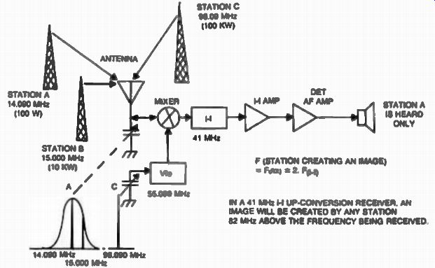
Fig. 16. Image with a 41 MHz i-f up-conversion receiver is 82 MHz
above the received frequency (96.090 MHz) and can be easily filtered
out at the preselector. The former image causing station at 15 MHz is
not a problem with this arrangement.
SELECTIVITY
The bandwidth of the information that we are trying to capture varies between about 8 kHz for amplitude modulation signals to as little as 300 Hz for continuous wave signals (Table 1). This selectivity is much easier to accomplish at lower frequencies such as the 455 kHz (the adjacent channel selectivity is accomplished in the i-f filter). We were simply not capable until the 1950s of providing i-f filters with this kind of bandwidth at frequencies much higher than 455 kHz. Humanity stumbled along for about 30 years with the 455 kHz scheme.
Before going any further, it should be mentioned that there is one advantage to the 455 kHz i-f, it is simple to implement. The image response, however, remains a problem to the present. Another approach to the front-end preselector which eliminates image problems while using a low i-f scheme will be presented later.

Table 1. Selectivity Requirements for Different Modes of Radio Communication.
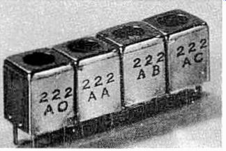
Fig. 17. Modem high-Q rf transformers used in commercial equipment.
INTERMEDIATE FREQUENCY FILTERS
The trend of i-f filter design started with high-Q rf transformers such as those shown in Fig. 17, and gradually progressed to mechanical, ceramic, and crystal filters, and also to surface-acoustic-wave (SAW) filters.
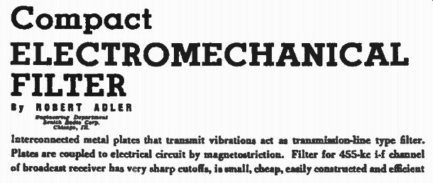
Fig. 18. Title reprinted with permission from Electronics, vol. 20,
pp. 100-105, copyright April, 1947.
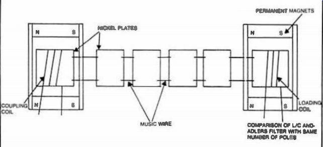
Fig. 19. The first 455 kHz mechanism filter-1946. Reprinted with permission
from Electronics, vol. 20, pp. 100-105, copyright April, 1947.
**Excerpts reprinted with permission from Electronics. Vol. 20. pp. 100-105. Copyright April 1947.
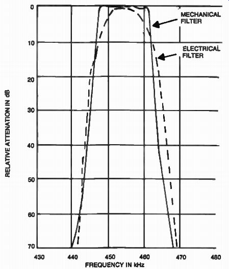
Fig. 20. Comparative frequency response curves between electrical
and mechanical filters used in 455 kHz i -Vs.
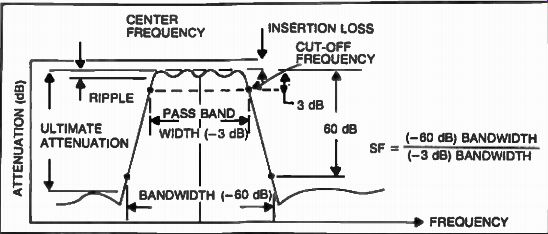
Fig. 21. Determining shape factor.
MECHANICAL FILTERS
The advent of i-f filters began in 1947 when Robert Adler of Zenith designed and built a six-element electro-mechanical filter for 455 kHz (Figs. 18 and 19). He writes: "Intermediate frequency currents, upon entering the filter, are converted into mechanical vibrations of the same frequency. These vibrations then pass through a structure resembling a ladder, consisting of several mechanically resonant metal plates coupled to each other by wires which act as springs.
This structure forms a bandpass filter for mechanical vibrations. Width of the pass band, as will later be shown, is determined by the design of each individual section and, because the several sections are all alike, bandwidth does not depend upon the number of sections. Attenuation outside the band limits, however, increases with the number of sections.*
[Author's note: *This is a theoretical case and assumes perfect square response. ] To understand the operation of the filter most easily, let us first consider a familiar electrical filter, composed of inductors and capacitors; the type shown in Fig. 1A (figure not shown) is rather fundamental and can be found in many books on electrical wave filters.
The analogy between electrical and mechanical network elements, with masses substituted for inductors and springs for capacitors, is well known; and it appears quite feasible to build a mechanical filler structure, which is fully equivalent to the electrical filter shown in Fig. 1A, by combining masses and springs in analogous fashion."
** Adler applied his filter to a 455 kHz i-f receiver. He notes: '71 was first suspected that such a set would be hard to tune, but tests with a number of lay listeners did not bear this out. Change in tone quality caused by incorrect tuning sets in at two clearly defined points much more abruptly than in conventional receivers; listeners seem to find it quite easy to tune between these points".**
['A device which transforms one kind of energy into another. In our case electrical signals are transformed into mechanical signals, or the other way around. ] Adler made several tests showing dear improvement against adjacent channel interference with his newly invented filter.
Although L/C filters are still being used, mechanical filters offered superior performance as shown in Fig. 20. Mass production of this type of filter was pioneered by the Collins Radio Company in 1947. By 1952, the first 455 kHz single sideband filters were produced in small quantity by this company. The popularity of such filters continues today when complex mechanical filters with twelve or more resonators can be fabricated with shape factors of as low as 1.25 (Method of measuring filter performance represented by the ratio between filter bandwidth at -60 dB and -3 dB, as shown in Fig. 21) and passband ripple as low as ±0.1 dB. The lower this number is, the better the filter is.
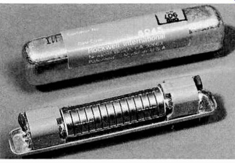
Fig. 22. Actual implementation of a modem twelve-disk mechanical filter
(courtesy of Rockwell International Corporation).
Figure 22 shows a modern twelve-disc mechanical filter produced by Rockwell International. The theory of operation for this filter is not much different than that of Adler's which was presented earlier. The technological implementation, however, departs considerably. While Adler's filter was using inefficient and lossy magnetostrictive-wire transducers*, this modern disk-wire mechanical filter uses piezo-technology (PZT) transducers in combination with ferrite cup cores and negative temperature coefficient capacitors (Fig. 23) in order to reduce the insertion loss to less than 3 dB and the passband ripple to under 2 dB, and maintain frequency stability over the temperature range of - 55°C to +85°C. (If the tempera ture performance is not a requirement, ferrite transducers could be substituted for the PZT transducers.) The bridging wires in both Fig. 22 and 23, allow for phase inversion needed to obtain attenuation poles, symmetrically, on both sides of the center frequency.
While Adler's filter was produced by laboratory methods, this modern implementation is the result of a highly technological production process which starts with six-foot long cylindrical bars made of a mechanically stable iron-nickel alloy, which was ground to a precise diameter, cut into disks of a certain thickness, then heat treated, and ground within .0002 inches accuracy. The individual disks are then frequency tuned, which is accomplished by drilling out a small amount of metal at their geometrical center. This operation is performed automatically in only seven seconds with the help of a computer-controlled drill-press equipped with frequency sensors which continuously measure and anticipate the resonance of the particular disk and then automatically shut off the drill motor when the right resonant frequency is achieved. The transducers follow somewhat of the same pattern. In the case of ferrite, iron-nickel oxide powders are wet mixed and extruded into rods similar to the iron-nickel bars. They are finally fired and cut to size before being attached to the metal disks. The final assembly incorporates the right number of disks, the transducers which are now attached to the ends, together with coils and magnets.
The bridging and coupling wires are spot welded automatically with the help of a computer-controlled machine which keeps track of the distance between the disks as well as the precise consistency of the weld. Finally, shock-absorbing rubber grommets are added before the final inspection is performed with the help of network analyzers, and the cover is put on by heat staking or automatic soldering.
Mechanical filters are easy to apply in i-f circuits as shown in Fig. 24 and Fig. 25.
CRYSTAL FILTERS
Today there are several types of i-f filters (Fig. 26), with the crystal lattice being by far the most widely used. Crystal technology improved considerably in the past 20 years; but one thing remains, it was harder to make filters into the MHz range than it was to make mechanical filters at 455 kHz.
A crystal filter usually consists of one to as many as twenty-eight individual quartz crystals, arranged together electrically by means of inductors, capacitors, and resistors, so that a certain bandpass characteristic is achieved. To best understand how this is implemented, we will consider a single individual crystal at resonance, as being a high Q series resonant circuit, as shown in Fig. 27. Q is a figure of merit for selectivity, indicating how sharp the frequency response is. Q's greater than 50,000 have been observed.
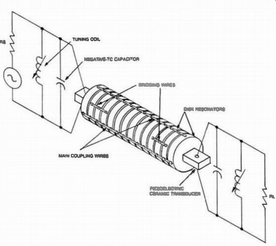
Fig. 23. Internal configuration of the disk-wire mechanical filter.
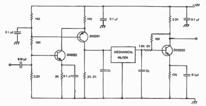
Fig. 24. Electrical implementation of a 455 kHz mechanical filter.

Fig. 25. Another i-f strip using 455 kHz mechanical filter.
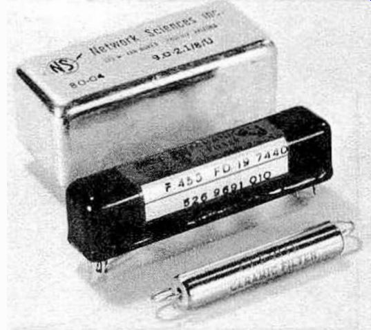
Fig. 26. Three types of modern i-f filters: Crystal lattice (top),
mechanical (center), and ceramic (bottom).

Fig. 27. Test set-up for a quartz crystal, showing its equivalent
high Q series resonant circuit.
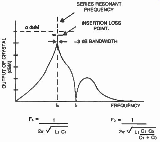
Fig. 28. Response characteristics of a quartz crystal. The highest
response is achieved at the series-resonant frequency (fs).
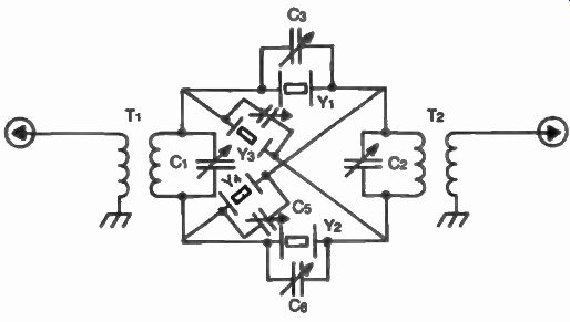
Fig. 29. A two section crystal-lattice filter. The transformers are
used as shunt inductances.
If the signal generator was swept slowly over a range of interest, a sharp output would be observed on the spectrum analyzer as we approach the resonant frequency of the crystal. The response characteristics of the one-pole crystal filter is shown in Fig. 28. (Quartz crystals exhibit other modes of resonance resulting in spurious outputs which are not considered in this example for reasons of simplicity.) It can be seen from this example that this pole has a very narrow band width, which can vary from a few hundred Hz to as much as 80 kHz, depending on the crystal frequency. The addition of carefully balanced series and parallel elements such as other crystals with slightly different frequencies and inductances and capacitances can create additional poles, and eventually a passband response with steep skirts (small shape factor) can be achieved. Figure 29 shows the schematic diagram of a two section crystal-lattice filter. In this example, the shunt inductances for the crystals are part of the input and output transformers. The crystals Y1 and Y2 are slightly different in frequency from crystals Y3 and Y4. In reality the series resonant crystals (Y1 and Y2) are tuned to the parallel resonance frequency of the other two crystals (Y3 and Y4) providing for a bandpass characteristic as shown in Fig. 30. Modern commercial and military crystal filters involve several individual crystals as shown in Fig. 31. The theory and design of such filters is several orders of magnitude and more difficult than that of an individual crystal. In such an electromechanical arrangement, quartz crystals can exhibit several modes of resonance, as we discussed earlier, resulting in complex interaction of such parameters as center frequency, bandwidth, shape factor, group delay, transient response, phase linearity, insertion loss, temperature, and aging, making for exhaustive mathematical analysis which is usually performed by computers. Networks with as many as thirty-two quartz crystals have been theoretically modeled by filter engineers, however, implementing such filters obeys natural laws not under stood yet by these computers. Complex quartz crystal filters are being manufactured by several companies. Figure 4-32 shows examples of such filters.
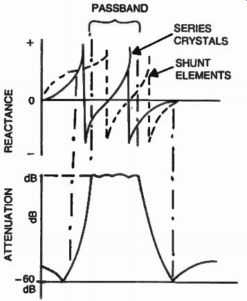
Fig. 30. Response characteristics of the two-section lattice filler.
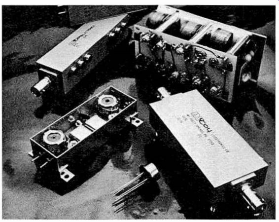
Fig. 32. Quartz crystal filters manufactured by McCoy Electronics
(courtesy of McCoy Electronics)
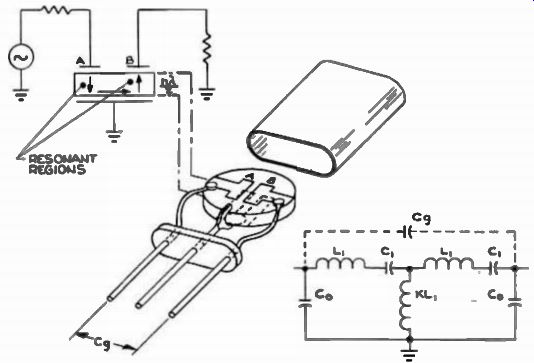
Fig. 33. A two resonator monolithic filter and its electrical equivalent.
The thickness of the crystal wafer equals n.) 1, where X is the operating
wavelength and 2 n is an odd integer. C9 is the gap capacitance between
leads, a limiting factor for the stop band rejection of the monolithic
filter.
MONOLITHIC CRYSTAL FILTERS (MCF)
A simpler way of achieving a quartz filter is the monolithic approach. In a monolithic filter, there are no discreet adjustments such as inductances and capacitors. Two electrode pairs are de posited on a quartz wafer (Electrochemical methods of depositing aluminum, silver, or gold are used in conjunction with AT cuts of quartz crystals) as shown in Fig. 33.
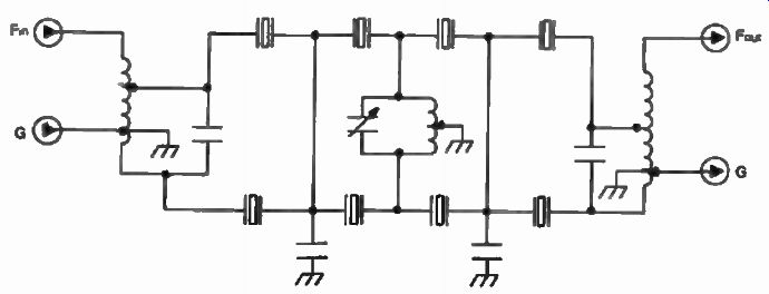
Fig. 31. Internal configuration of a commercial eight-pole crystal-lattice
filter (XF-9B) available from KVG* ( Kristallverarbeitun Neckarbischofsheim,
West Germany; available from Spectrum International). Each stage is made
of tuned half-lattice sections with one crystal in each branch.

Fig. 34. A multi-resonator monolithic filter with eight electrode
pairs on a single substrate.
A sound wave generated at electrode A travels through the crystal wafer to electrode B, at the two resonant regions as shown in our example.
The thickness of the wafer at the two points determines the band-pass characteristic of the monolithic filter.
This "folded" approach to acoustically coupled resonators was not fully understood until 1965 when R. A. Sykes at Bell Telephone Laboratories, and M. Onoe in Japan discovered (simultaneously) the mathematics governing this mechanism.
This event led to the development of multi-resonator monolithic filters such as the one shown in Fig. 34. However, the inability to tune out unwanted elements, such as in a conventional quartz filter, limits the practical number of resonators in a monolithic to four pairs. While in a conventional quartz filter, the interaction of unwanted parameters could be minimized by adjusting variable elements such as capacitors and inductances, in a monolithic filter, this interaction is a fixed function of the mechanical arrangement, and is further aggravated by indirect sound paths of unpredicted nature between the input and output, producing spurious responses and degrading the stop-band attenuation of the filter.
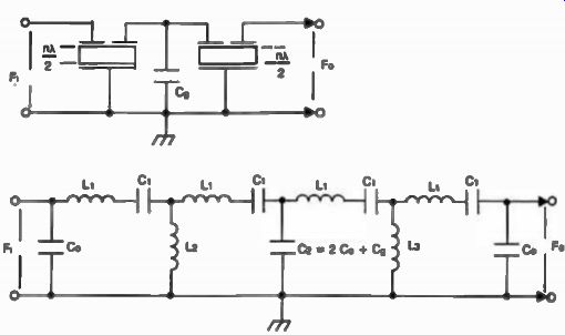
Fig. 35. Two two-pole monolithics are connected in tandem for increased
stop-band attenuation and ease of manufacturing.

Fig. 36. A practical implementation of eight-pole tandem monolithic
filter centered at 75 MHz (-6 dB bandwidth is - ±13 kHz) such a filter
could be used in the first i-f of a double conversion superheterodyne.
For reasons of simplicity the 4171 F filter is shown at a two-pole monolithic.
An amplifier can also be used between the filters In order to provide
better isolation.
The control of factors such as the quality of etching for the electrodes, or the polishing of the quartz, play an important role in cancelling these effects, making it very hard for such filters to be produced economically. As manufacturing techniques improve, this type of filter will become increasingly popular.
New technological breakthroughs, such as ion etching combined with sophisticated polishing techniques, as well as the use of other than quartz materials such as lithium niobate, lithium tantalate, and bismuth germanium oxide, will allow for increasingly complex monolithic filters to be built on the same substrate.

Fig. 37. Preferred layout for the 75 MHz tandem monolithic filter.
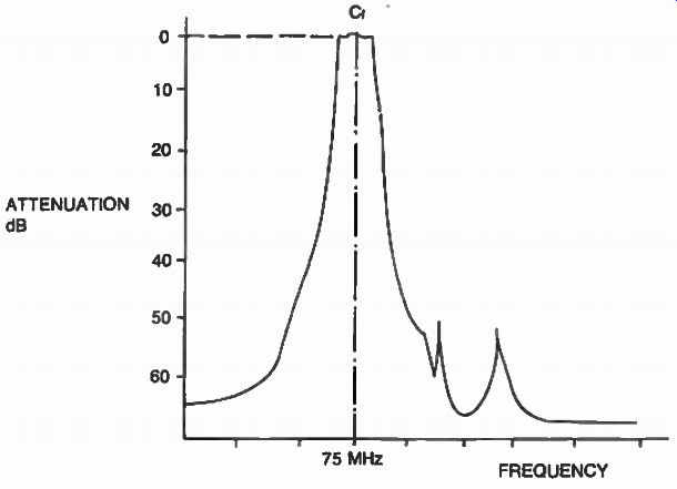
Fig. 38. Frequency response of the 75 MHz tandem monolithic filter.
THE TANDEM MONOLITHIC
One way of achieving greater selectivity without the calibration problems of the multi-resonator monolithic is to connect two or more simple two-resonator monolithics in a tandem fashion as shown in Fig. 35.
In this arrangement, control over the electrical parameters of each monolithic is guaranteed by the less demanding manufacturing process and the tandem design provides for increased stop-band attenuation by minimizing the effect of unwanted modes. Filters with as many as ten resonators have been manufactured by this technique. Figure 36 shows an actual implementation of an eight-pole tandem monolithic with a center frequency of 75 MHz. Two 4171F monolithic filters from Piezo Technology, Inc. are used in this example. A preferred layout is also given (Fig. 37) for minimum interaction of the elements. The frequency response of the filter is shown in Fig. 38.

Fig. 39. Electrical configuration of a fifteen disc ceramic ladder
filter.
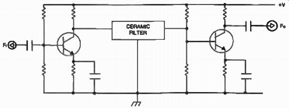
Fig. 40. Typical implementation of a ceramic filter in an i-f.
CERAMIC FILTERS
Where size and cost are important in a receiver design, the ceramic piezoelectric filter is used in the i-f. Such filters usually operate at 455 kHz, although higher frequencies have been achieved with this technology. The electrical performance of the ceramic filter resembles that of the quartz crystal filter, however, piezoelectric ceramics do not exist in natural form.
The complicated manufacturing process starts with ceramic compositions such as lead zirconate-titanate and lead metaniobate. These powders are mixed with water in order to produce a paste which is further formed into discs of a certain size. The discs are then dried out, before being baked at high temperatures, much like bricks in a ceramic factory. It is in the baking process that a high voltage "poling" field is applied in order to give them the piezoelectric property.
This shock distorts the physical shape and electrical properties of the ceramic structure creating a permanent piezoelectric element, like a powerful magnet would magnetize a ferric material. Silver electrodes are then deposited on each side of the discs, and a ladder arrangement can be accomplished by stacking as many as fifteen or more elements in a tubular package. Figure 39 shows the electrical equivalent of a ceramic ladder filter. Other configurations such as monolithics are also achievable with this technology.
Ceramic filters are easy to implement as shown in Fig. 40. Their biggest drawback is their relative frequency instability with temperature which could be an important requirement in certain applications.
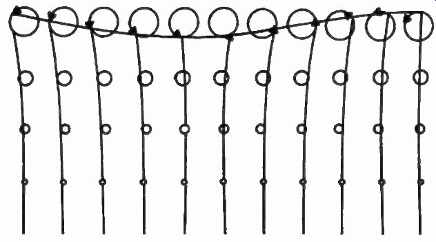
Fig. 41. Propagation of a surface acoustic wave across a quartz crystal
substrate showing actual motion of particles. Secondary vertical propagation
is also shown by the smaller circles spaced at about a tenth wavelength
from each other in the vertical plane.
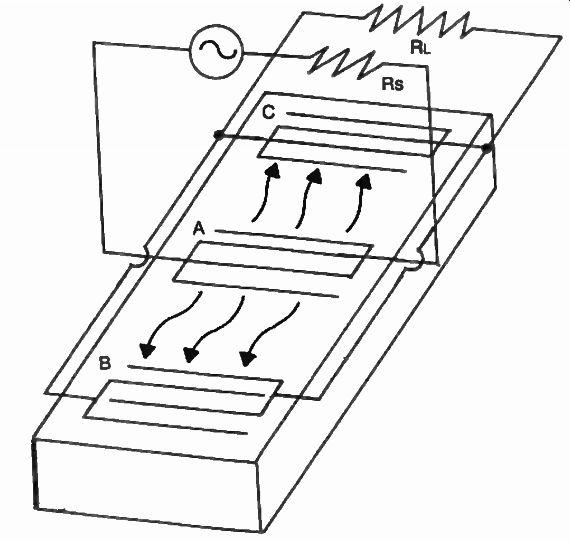
Fig. 42. A typical implementation of a SAW filter. Transducer A emits
surface waves in both directions to be intercepted by transducers B and
C, which are electrically coupled together for minimum loss.
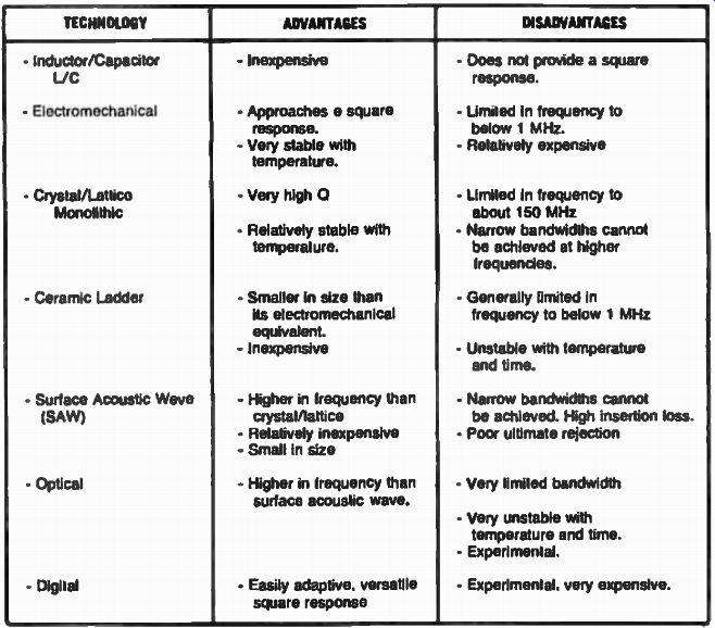
Table 2. Advantages and Disadvantages el Several Technologies Used
in l-f Filter Design.
SURFACE ACOUSTIC WAVE (SAW) FILTERS
The SAW filter takes advantage of the acoustic wave propagation in piezoelectric materials, but unlike the quartz monolithic filter, which uses transversal propagation properties, the SAW uses mechanical waves that propagate at the surface of the solid substrate, via actual motion of the particles, much like a water wave in an ocean. This is shown in Fig. 41. A surface-acoustic-wave (SAW) filter usually consists of three sets of transducers which are electrochemically deposited on the surface of a piezoelectric crystal as shown in Fig. 42. These thin aluminum electrodes (chosen for minimum mechanical mass) are spaced V4 or 1/2 wavelength from each other.
If transducer A is excited at the frequency of interest, a surface wave will be generated simultaneously toward the intercepting transducers B and C providing the same output at both locations. If only one receiving transducer was used, half the energy would be lost, thus a higher insertion loss. The two outputs are electrically paralleled in order to minimize the insertion loss characteristic of the filter. Other methods of focusing the acoustic energy are also used.
The main advantage of the surface-acoustic-wave (SAW) filters is the relatively slow propagation rate of these types of waves, compared with electromagnetic waves. This velocity is 3 x 10³ m/sec or about 100,000 times slower than the speed of light, allowing technological and physical feasibility for filters at very high frequencies, typically from 10 MHz to 2,000 Mhz. Practical surface-acoustic-wave (SAW) filters have been realized at frequencies from 20 to 600 MHz. They are inherently small, rugged, and reliable, and require no adjustments like the monolithics. However, they suffer from the same problems as the monolithics do.
(Inferior ultimate rejection due to interaction of unpredicted modes of wave propagation with the surface wave.) Although the initial cost is higher than other technologies, surface-acoustic-wave (SAW) filters are ideally suited for mass production, because of the lithographic manufacturing techniques that can be used with this type of filter.
TECHNOLOGICAL TRADEOFFS IN INTERMEDIATE FREQUENCY (I-F) FILTERS
We discussed several methods of achieving selectivity in the intermediate-frequency (i-f) portion of a superheterodyne receiver. New ways of intermediate frequency (i-f) filtering are being developed today and among them are the optical and digital filters. Although a thing of the future, these filters will provide certain advantages over the previously used technologies. A look at Table 2 will show a list of technological trade-offs between the various methods discussed, and provide us with a better understanding of their merits and their limitations, as we will apply them to communication receivers in the following Sections.