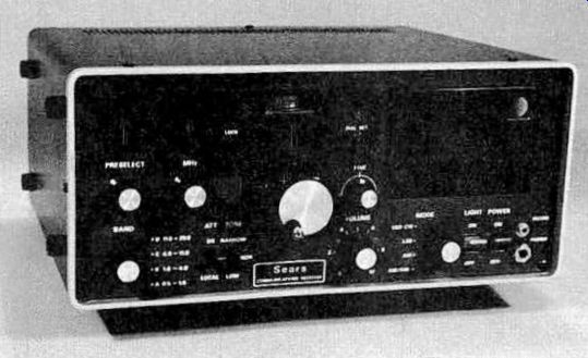
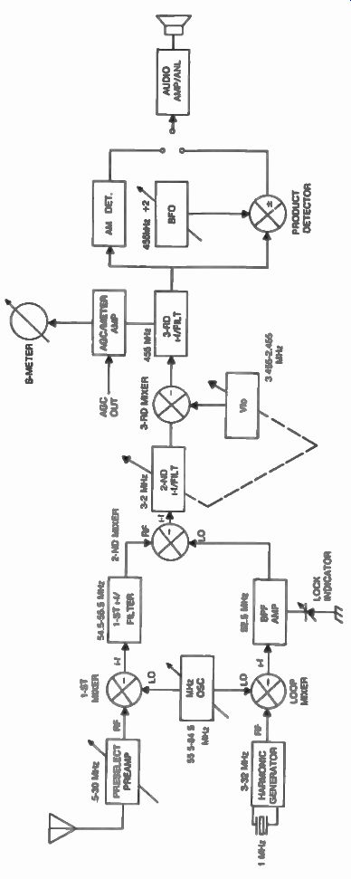
One of the most ingenious receivers ever created is the Barlow Wadley receiver, invented by Dr. Wadley of South Africa. Fig. 1 shows several examples of this type of receiver. A look at the block diagram in Fig. 2 shows a triple conversion approach with the first i-f at 55 MHz, the second i-f at 2.5 MHz, and the third i-f at 455 kHz. A 1 MHz crystal oscillator generates local oscillator signals at exactly 1 MHz intervals (this is a type of synthesizer) anywhere between 3 MHz to 32 MHz (Fig. 3). These twenty-nine harmonics are all fed to one side of the loop mixer, as shown. A separate variable oscillator which oscillates between 55.5 MHz to 84.5 MHz (called the MHz oscillator) is manually controlled by the operator, and is fed simultaneously to the loop mixer, as well as to the first mixer of the receiver where it combines continuously with the incoming preselected signal, generating the first i-f centered at 55 MHz. This information is further filtered and amplified through the first i-f filter. The signal which now has a bandwidth of one megahertz (54.5 MHz to 55.5 MHz) and contains all of the r-f signals present at the antenna within one megahertz of the tuned frequency is finally fed to one side of the second mixer. The other side of the second mixer is powered from the loop mixer, through a narrow bandpass filter amplifier centered at 52.5 MHz.

Fig. 1. Barlow Wadley type receivers.

Fig. 2. Block diagram of a typical Barlow Wadley receiver (YAESU,
FRG-7).

Fig. 3. Harmonic generator of the YAESU, FRG-7 receiver

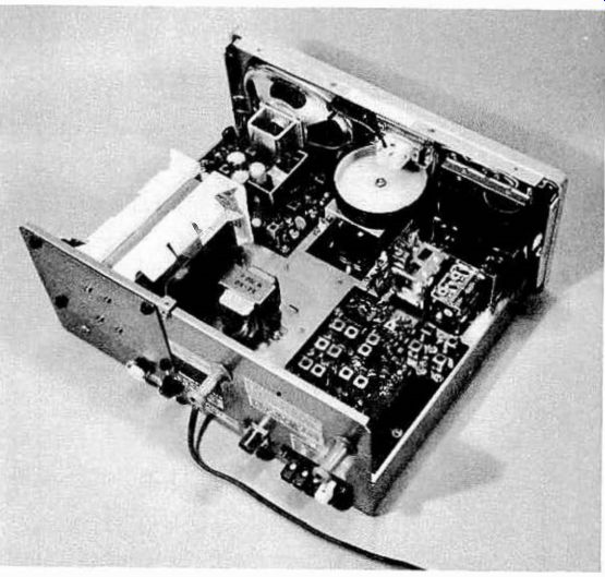
Fig. 4. Internal view of the YAESU, FRG-7 receiver.

Table 1. Example of Selective Mixing Process in the Loop Mixer of
a Typical Barlow Wadley Receiver.

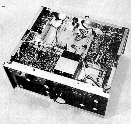
Fig. 5. The harmonic generator (upper left) in a Barlow Wadley receiver
is placed in a shielded box (shown with cover removed) far away from
critical r-f areas.
It can be seen that the 52.5 MHz signal will only be true at precisely 1 MHz intervals as a result of the selective mixing process which takes place in the loop mixer, as shown in Table 9-1. The biggest advantage of this scheme is the drift cancelling mechanism provided for the MHz oscillator by the double mixing approach. The drift is completely eliminated by the subtraction process in the second mixer, providing stable conversion for the second i-f.
The second i-f fulfills the bandwidth range requirements for a multi conversion receiver (as discussed earlier) and tunes from 3 MHz to 2 MHz via a variable capacitor which tracks together with the Vfo, operating from 3.455 MHz to 2.455 MHz. This provides the fine-tuning conversion for the third i-f which is centered at 455 kHz within any of the 1 MHz bands previously selected. The 455 kHz i-f is further processed through narrow filters and amplifiers, and is finally detected and fed to the speaker via the audio amplifier (Fig. 4). A disadvantage of the Barlow Wadley scheme is that the signals produced by the harmonic generator are usually heard at the beginning and the ends of each 1 MHz band as a result of system leakage, in spite of the fact that this generator is usually shielded and placed far away from critical areas as shown in Fig. 5. This problem, however, can be considered as an advantage as it provides a means of dial calibration for the Vfo. The Barlow Wadley scheme remains as a widely used scheme and a symbol of technical ingenuity.