29-1 AC/DC SUPERHETERODYNE RADIO RECEIVER
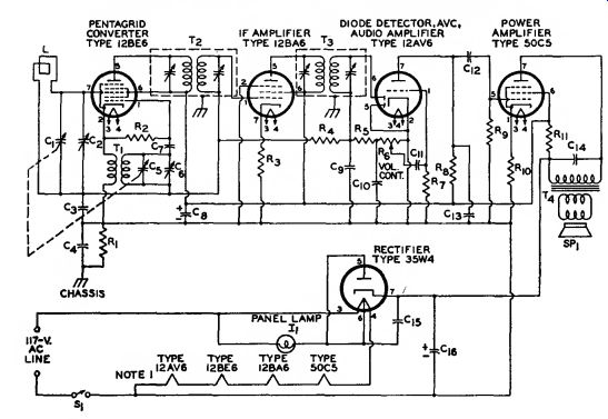
Parts List
C1, Cs=Ganged tuning capacitors ; C1, 10-365 pF.
Cs, 7-1IB pF
C1=Trimmer capacitor, 4-30 PF
Ca=0.05 uF, paper, 60 V C<=0.1 uF. paper, 400 V C«=:Trimmer capacitor, 2-17 pF Ct=56 pF, ceramic C«=30 uF, electrolytic, ISO V C», C1o=150 pF. ceramic Cn, C1<=0.02 uF, paper, 400 V C1i=0.002 nF, paper, 400 V C1a=330 pF, mica C1s=0.05 uF, paper, 400 V Cw=B0 «F, electrolytic, 150 V
Ii=Panel lamp, No. 40 or 47
L=Loop antenna or ferrite rod antenna, 540-1600 kHz (with specified values of capacitance for C1 and Cjt) Ri=0.22 megohm, 0.5 watt Ri- 33000 ohms, 0.5 watt
Ra= 100 ohms, 0.5 watt
R4=3.3 megohms, 0.5 watt
Rs=47000 ohms, 0.5 watt
Re=Volume control, potentiometer, 0.5 megohm
R7=4.7 megohms, 0.5 watt
Rb, Re=0.47 megohm.
0.5 watt
Rio=150 ohms, 0.5 watt
Ru=1200 ohms, 1 watt
S1=On-off switch ; single pole, single-throw
SPi=Speaker
Ti== Oscillator coil for use with 7-115 pF tuning capacitor and 455-kHz inter mediate-frequency transformer
Tj, Ta=Intermediate-frequency transformers, 455 kHz (permeability-tuned type may be used)
Ti=Output transformer for matching impedance of voice coil to 2500-ohm load
Circuit Description
This basic five-tube superheterodyne radio receiver operates directly from an ac power line or a dc supply of 117 volts. AC power inputs are converted to dc power by the 35W4 half wave rectifier circuit. The receiver uses a series heater arrangement.
With ON-OFF switch St closed, the heater string is connected directly across the 117-volt input terminals.
A 6.3-volt panel lamp Ii connected be tween heater pins 3 and 6 of the 35W4 rectifier tube lights to indicate that power is applied to the receiver.
A ferrite-rod or loop antenna L and tuning capacitor d select amplitude-modulated rf signals from the desired broadcast-band (550 to 1600 kHz) radio station and couple these signals to grid No. 3 (pin 7) of the 12BE6 pentagrid converter. A local oscillator signal, developed by the resonant circuit formed by oscillator coil Ti and variable capacitors C5 and C6, is also applied to the 12BE6 pentagrid converter, at grid No. 1 (pin 1). The modulated-rf and local-oscillator signals are mixed across the nonlinear impedance of the converter tube to produce the 455-kHz inter mediate frequency used in the receiver. The antenna and oscillator tuning capacitors C25 and C27 are mechanically ganged so that the antenna and oscillator resonant circuits can be adjusted together to maintain the 455-kHz difference frequency for any dial setting in the broadcast-frequency band. Trimmer capacitors C26 and C25 are adjusted to assure that the desired tracking relationship is maintained across the band. Positive feedback to sustain oscillations is inductively coupled by Tt from the cathode of the 12BE6 converter to the local-oscillator resonant circuit.
A single if stage, which uses a high-transconductance 12BA6 remote-cutoff pentode, provides the required amplification of the intermediate-frequency signals. This stage is made selective at 455 kHz by the double-tuned input and output trans formers T2 and T3. Audio-signal components are extracted from the if signal by the second-detector circuit, which consists of the pin 6 diode section in the 12AV6 tube and associated components. (The pin 5 diode section of the 12AV6 is not used and is shorted to the tube cathode, pin 2.) The audio output from the detector is developed across the VOL. CONT. potentiometer R6, which provides manual adjustment of the out put sound level of the receiver. The detector also develops a negative dc voltage proportional to the rf input across a 150-picofarad capacitor C9 for automatic volume control in the receiver. This avc voltage is used as bias for the converter and if amplifier and automatically controls the gain of these stages.
The audio-signal voltage at the wiper arm of the VOL. CONT. potentiometer is amplified by the triode (audio-voltage-amplifier) section of the 12AV6 and is then used to drive the 50C5 audio output stage. The out put stage develops the audio power required to produce an audible out put from the speaker. Audio output transformer T4 matches the 2500-ohm plate-load impedance of the 50C5 to the speaker voice coil.
29-2 AM/FM SUPERHETERODYNE RADIO RECEIVER
Circuit Description
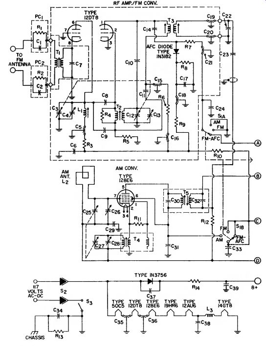
This AM/FM radio receiver operates directly from either an ac power line or a dc supply of 117 volts.
AC power inputs are converted to dc power by a 1N3756 silicon-rectifier half-wave power supply. The receiver uses a series heater string, which is connected across the 117-volt input when ON-OFF switch Sa and inter lock are closed. The interlock assures that power is automatically disconnected when the receiver is removed from the chassis.
AM or FM operation of the receiver is selected by means of switch S,. For AM operation (S, set to AM position), amplitude - modulated rf signals in the AM broadcast band (550 to 1600 kHz) from the desired radio broadcast station are selected by antenna L» and tuning capacitor C1b. These signals are amplified and converted to the 455-kHz AM inter mediate frequency by the 12BE6 pentagrid converter. Tuning capacitors C25 and C27 are mechanically ganged so that the antenna and local-oscillator sections of the converter can be tuned simultaneously to maintain the 455-kHz difference frequency for any station setting. Trimmer adjustments are provided by variable capacitors CL„ and C,,.
Parts List
C1=Part of P C1
C2=Part of PCs Cs, C1s= Ganged tuning capacitors ; tune L1 and Ts to 88-108 MHz C1, C1^-Trimmer capacitors, 1-7 pF Cs, Cm, C1s=1000 pF, feed through. 500 V Co=0.1 uF, ceramic, 500 V C7=36 pF, ceramic, 600 V C8, C1»=6.8 pF, ceramic, 500 V C9=ll pF, ceramic, 500 V C1o=68 pF, ceramic, 500 V
Cu=21 pF, ceramic, 500 V C1s=500 pF, feedthrough, 500 V
Cu=0.22 uF, ceramic disc, 500 V
C1», C=o=2 pF, feedthrough, 500 V
C21, Cm, Cm=2000 pF, feedthrough, 500 V
Cs2=IF transformer tuning capacitor ; value, with cable capacitance, tunes T3 to 10.7 MHz
With switch S1 in the FM or FM AFC position, the FM tuner selects rf signals in the FM broadcast band (88 to 108 MHz) from the desired FM radio station, amplifies these signals, and converts them to the 10.7 MHz FM intermediate frequency. The rf-amplifier and converter stages of the tuner each use one section of a 12DT8 high-mu twin triode. Ganged tuning of the rf-amplifier and converter tuning capacitors, C3 and C12, assures that the converter local-oscillator frequency tracks the input tuning at 10.7 MHz above the center frequency of the FM channel selected.
Trimmer adjustments are provided by variable capacitors C4 and CJ3 .
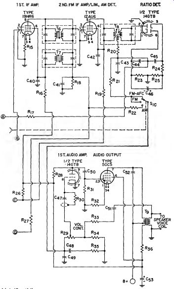
The 19HR6 if amplifier is used in both FM and AM modes of operation. Depending upon the setting of selector switch Si, this stage amplifies the frequency-modulated 10.7 MHz intermediate-frequency output from the FM converter or the amplitude-modulated 455-kHz intermediate-frequency signal from the AM converter. Additional amplification of FM if signals is provided by the 12AU6 pentode stage, which is used as a combination second FM if amplifier and noise limiter. A portion of the 12AU6 stage is also used as a second detector circuit to extract the audio-signal components from the 455-kHz AM if signals. For this demodulation function, the cathode and control grid of the 12AU6 are used as the detector diode. The 10.7-MHz FM if signals are demodulated and amplitude distortion is removed by a ratio detector that uses the diode sections of a 14GT8 twin diode-high mu triode. Good selectivity in the if amplifier and detector at 10.7 MHz is provided by the double-tuned transformers T3, T6, and T8, and at 455 kHz by the double-tuned transformers T., and T,.
Depending upon the mode of operation, a section of S1 selects the audio output from the AM detector or from the FM ratio detector. The selected audio output is amplified by an audio voltage amplifier which uses the high-mu triode section of a 14GT8 and a 50C5 audio output stage. The output stage provides the power necessary to produce the required speaker output. Transformer To matches the 2500-ohm plate impedance of the 50C5 to the speaker voice coil. Manual adjustment of the receiver output is provided by the VOL. CONT. potentiometer Ra, in the control-grid circuit of the audio voltage amplifier.
A negative dc voltage proportional to the input signal level is developed across R)8 and Cu during either AM or FM operation of the receiver. This voltage is applied as bias to the control grid (pin 1) of the 19HR6 if amplifier and the signal grid (pin 7) of the 12BE6 AM converter to provide automatic gain control of the receiver in each mode of operation.
With S1 in the FM-AFC position, the 1N3182 AFC diode rectifies the voltage across the tertiary winding of the ratio-detector transformer T8. The resultant frequency-sensitive voltage, applied to the plate resonant circuits of the FM rf-amplifier and converter stages, provides automatic frequency control in the FM tuner.
Note : See general considerations for construction of high frequency and broad-band circuits on page 675.
Cei=4700 pF, ceramic, 500 V Cm=0.15 u-F, paper, 200 V Css, Car=Ganged tuning capacitors ; tune T* to 540-1650 kHz Cm, Css=Trimmer capacitor, 12 pF Cm, Go, Css, C«=0.01 mT.
ceramic, 500 V Cao=Part of Ts C31, C«=1000 pF, ceramic, 600 V Ca»=Part of Ts Cm=0.1 11F, ceramic, 500 V Cm=0.047 uF, paper, 400 V C»=80 uF, electrolytic, 150 V Cm, C«=2700 pF, ceramic, 500 V C«, C«=100 pF, ceramic, 600 V, NPO C41, C4s=330 pF, mica, 500 V C«=2 11F, electrolytic, 50 V C«=0.01 11F, paper, 200 V Gso=5600 pF, ceramic, 500 V Coi=0.1 uF, paper, 200 V Css=0.022 uF, paper, 200 V Cs3=60 11F, electrolytic, 150 V la, La= 1 nK, i f coil Lj- Antenna, air-loop type with back cover P C1, PCs= Printed circuit; includes 0.5 megohm, 0.25-watt resister and 470 picofarad, 500-volt capacitor ; RCA Stock No.
104328 R1=:Part of P C1 R3=Part of PC2 Ra=2200 ohms, 0.5 watt R4=I200 ohms, 0.5 watt Rs, Ra=33000 ohms, 0.5 watt Ro, Ru=22000 ohms, 0.5 watt R7, R28, Rsi=0.47 megohm,
0.5 watt R»=3900 ohms, 0.5 watt R», R2»=47000 ohms, 0.5 watt Rio=220 ohms, 0.5 watt R12, Ri7=l megohm, 0.5 watt Ria=0.22 megohm, 0.5 watt Ri4=100 ohms, wire-wound, 4 watts Rw, Ra>=68 ohms, 0.5 watt Rio=4700 ohms, 0.5 watt Ris=0.33 megohm, 0.5 watt Rio, Rsi=1000 ohms, 0.5 watt R23, R25=6800 ohms, 0.5 watt Rm=220 ohms, 0.5 watt Rjt=3.3 megohms, 0.5 watt Ra>= Volume control, potentiometer, 1 megohm, part of assembly with S3 Rao=4.7 megohms, 0.5 watt R.b=150 ohms, 0.5 watt R:a=1500 ohms, 0.5 watt Rm=820 ohms, 0.5 watt Ras=3900 ohms, 0.5 watt Rm=560 ohms, 0.5 watt Si=AM-FM-AFC selector 3-section slide switch Sa=Interlock &=ON-OFF switch, part of assembly with Rsa Ti=FM antenna transformer Ts=FM oscillator trans former T3, Te=FM if transformer, 10.7 MHz T1=AM oscillator coil ; with specified values of tuning and trimmer capacitance, tunes to 540 to 1600 kHz Ts, T7=AM if transformer, 455 kHz Ts=Ratio-detector trans former, 10.7 MHz T9~Audio output trans former, matches impedance of speaker voice coil to 2500-ohm tube load
29-3 FM TUNER
Circuit Description
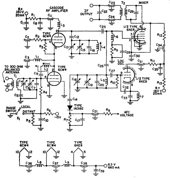
This three-stage FM tuner features a pair of 6CW4 nuvistor triodes operated" in a low-noise, high-gain cascode rf-amplifier stage. The mixer and local-oscillator sections of the tuner use the pentode and triode sections, respectively, of a 6KE8 triode pentode. The dc operating power for the tuner is obtained from a 180-volt, 20-milliampere supply. Power for the tube heaters is obtained from a 6.3 volt, 660-milliampere ac source.
The tuner uses a 300-ohm balanced antenna. Antenna transformer T1 matches the 300-ohm antenna impedance to the input circuit of the cascode rf amplifier. Antenna tuning capacitor C4 is adjusted to select the desired FM channel. The frequency modulated rf signals are amplified by the cascode rf stage and coupled to the control grid of the mixer stage.
The local oscillator generates a signal, at a frequency 10.7 MHz above the center frequency of the selected FM channel, which is also applied to the control grid of the mixer stage.
The rf and local-oscillator signals are mixed to produce the desired 10.7 MHz FM intermediate frequency.
Ganged tuning of the antenna, mixer, and local-oscillator tuning capacitors, C<, C13, and Go, assures that the local oscillator frequency tracks the input tuning at 10.7 MHz above the selected FM channel. Capacitors G, G«, and do are trimmer adjustments for the tuner. The double-tuned transformer T2 selects the 10.7-MHz FM if signals at the plate of the mixer stages and couples them to the if-amplifier/ limiter section of the FM receiver.
* A metal shield should be provided between grid and plate terminals on the 6CW4 socket.
Parts List
C1, Cs, Cm, Ca>=0.01 uF, ceramic disc, 400 V
C1, C3i=2000 pF. feed through, 400 V
Cj, Cn, Ca, Cs», Can, C37, C38=1000 pF feedthrough, 400 V
C1, Cjs, C1o=Ganged tuning capacitor ; 6.6-23 pF, 400 V ; Miller No. 1461-BS or equiv.
Cs, C», Css^1000 pF, ceramic, 400 V Co, C15, C1»=Trimmer capacitors, 1-7.5 pF, ceramic, 400 V Ct, C18, Ckj=10 pF, ceramic, 400 V C10- 2000 pF, ceramic disc, 400 V C1=, Cao=2000 pF, ceramic, 400 V C14, C32=6.8 pF, ceramic, 400 V d-=0.22 #F, ceramic, 400 V C2o=18 pF, ceramic, 400 V C-j2= Capacitor inserted in place of tuning capacitor in secondary winding of value with cable capacitance tunes output circuit of tuner to 10.7 MHz Cj::, C14=2 pF feedthrough, 400 V
Cm=22 pF, ceramic, 400 V
Ck=2.2 pF, ceramic, 400 V
Cm=47 pF, ceramic, 400 V C»9=Part of T2
Li=EF coil, 5 turns of No. 22 enamel wire close wound on ^4 -inch-diameter coil form La=RF coil, 12 turns of No. 22 enamel wire close wound on \± -inch-diameter slug-tuned coil form ; tuning slug = %-inch-long Moldite No. 6101 ferrite or equiv.
La=HF choke, 4 11H, 3. W.
Miller No. 70F396A1 or equiv.
Li=EF coil, 3 turns of No. 16 enamel wire wound double-spaced on M-inch diameter slug-tuned coil form ; tuning slug = 3/8 inch-long Moldite No. 5101 ferrite or equiv.
Ls=RF coil, 1-Ms turns of No. 16 enamel wire close-wound on H-inch-diameter slue-tuned coil form tuning: slug:= 3/8-inch-long Moldite No. 5101 ferrite or equiv.
Le=RF choke, 2uH, Ohmite No. Z144 or equiv.
Lr=RF coil; 0.4 /*H;20 turns of No. 26 enamel wire close-wound on a 0.47 megohm, 0.5-watt Allen Bradley resistor or resistor of equivalent physical size ha, Le=RF chokes ; 1/tH ; 25 turns of No. 24 enamel wire close-wound on a 0.47 megohm, 1-watt Allen Bradley resistor or resistor of equivalent physical size R1, Ri3=220 ohms, 0.5 watt R2- 5 ohms, 0.5 watt Ra, R»=0.47 megohm, 0.5 watt Rt, Re, Rs=47000 ohms, 0.5 watt Rs=0.1 megohm, 0.5 watt R7rr 3900 ohms, 0.5 watt Rio= 22000 ohms, 0.5 watt R11=4700 ohms, 0.5 watt R12- 15000 ohms, 0.5 watt Si=AM/FM range switch open position is used for local stations, closed position for distant stations Ti=Antenna transformer; primary : 2 turns of No. 32 wire with type B nylon insulation, Alpha No. 1860 or equivalent, center tapped ; secondary : 3 turns of No. 16 enamel wire wound double-spaced on 3/8-inch-long coil form ; tuning slug = 3/8-inch-long Moldite No. 5101 ferrite or equiv.
Ts=FM if transformer, 10.7 MHz ; J. W. Miller 1451 or equiv. ; capacitor in secondary should be replaced by C22
Note: See general considerations for construction of high-frequency and broadband circuits on page 675.
29-4 THREE-STAGE IF AMPLIFIER/LIMITER AND DETECTOR
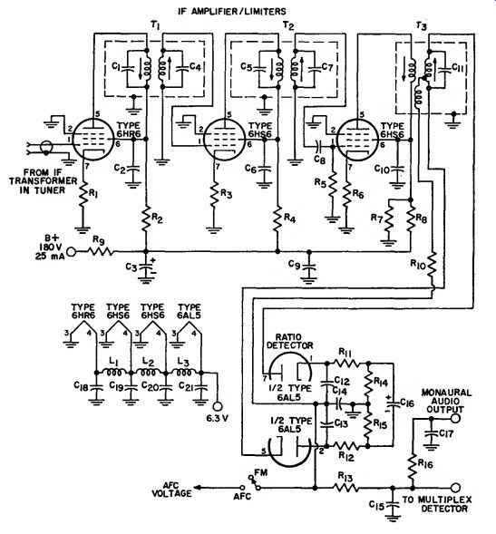
For Monaural or Stereo Tuner
Circuit Description
This three-stage if amplifier/ limiter and detector circuit, when used with a front-end circuit such as that shown in circuit 25-3, makes possible an over-all tuner gain of 35 dB.
The over-all bandwidth of the if amplifier stages, between the 6-dB down points, is 300 kHz, and the peak separation of the detector is 440 kHz.
The circuit provides a signal-to-noise ratio of 20 dB for an input of 2.8 microvolts or 30 dB for an input of 4.1 microvolts. The 6HR6 and 6HS6 pentodes used in the if-amplifier stages have very high transconductance and a grid-No.1-to-plate capacitance substantially less than 0.01 picofarad and are, therefore, especially suited for use in FM if amplifiers and television sound if amplifiers. These pentodes operate from a 180-volt, 25-milliampere dc supply.
Heater power for the pentodes and for the 6AL5 twin diode used in the ratio detector is obtained from a 6.3 volt ac source.
The frequency-modulated, 10.7 MHz intermediate-frequency signal from the mixer stage in the FM tuner is applied to the control grid of the first if-amplifier stage. This signal is amplified by the three transformer coupled amplifier stages and applied by transformer Ts to the ratio detector. The doubled-tuned coupling transformers Ti, T», and T» provide the selectivity at 10.7 MHz and the band pass characteristics required for optimum transfer of the frequency modulated signal. Circuit stability is improved by the use of unbypassed cathode resistors in each amplifier stage. The first two if stages are basically amplifiers, although they provide some saturation limiting of large-level signals. The 3300-ohm screen-grid dropping resistors (R2 and R) reduce the screen-grid voltages in these stages to obtain the desired limiting characteristics. The 6HR6 pentode used in the first if amplifier is a remote-cutoff tube and, if desired, this stage may be operated with age bias. The 6HS6 pentodes used in the second and third if stages are sharp-cutoff tubes. In addition, the screen-grid voltage divider net work (Rt and Rs) for the third stage substantially reduces the screen-grid voltage so that the stage will provide both cutoff and saturation limiting of large-level signals. The limiting in the if stages helps remove any amplitude modulation from the frequency-modulated signals.
Parts List
C1, C»=Part of Ti Cs, C«=2200 pF, ceramic disc, 400 V
Ca=50 uF, electrolytic, 450 V Cs, C1=Part of Ti
C>=47 pF, ceramic disc, 400 V
Co, Cu, Cu, Cm, Czi:=0.01 uF, ceramic disc, 400 V
Cu>=1600 pF ceramic disc, 400 V Cu=Part of Tj
Cu, C1a, C15=330 pF, ceramic disc, 400 V
Cu=100 pF, ceramic disc, 400 V
C1«=2 uF, electrolytic, 400 V C17=1000 pF, ceramic disc, 400 V Li, I-.2, Ls=l /iH Ri, Rs=68 ohms, 0.5 watt
R2, Ri, Rix=3300 ohms,
0.5 watt Rs=0.1 megohm, 0.5 watt
Rt, Rio=100 ohms, 0.5 watt
Rt= 15000 ohms, 0.6 watt Rs=22000 ohms, 0.5 watt
Rg=2200 ohms, 3 watts Rii=1200 ohms, 0.5 watt
Rut=390 ohms, 0.5 watt Ri<, Ris=6800 ohms,
0.5 watt Ri»=68000 ohms, 0.5 watt
T1, T2=IF transformers, 10.7 MHz
Ts=Ratio-detector transformer, 10.7 MHz
Note: Tube shields may be required if regeneration is encountered. See general consideration* for construction of high-frequency and broad-band circuits on page 676.
The 6AL5 ratio-detector circuit provides additional noise limiting of the FM signal and demodulates this signal to recover the audio information. The detector circuit provides the input to the audio amplifiers of a monaural receiver or to the multiplex detector in a stereo system. The RC network ( Rio and Cu) in the monaural output lead provides the desired deemphasis of high audio frequencies.
29-5 Circuit Description
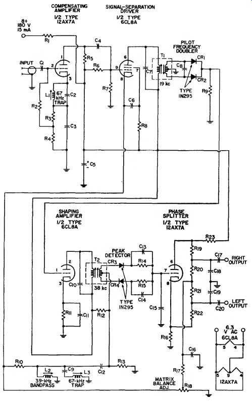
FM STEREO MULTIPLEX ADAPTER
This FM stereo multiplex adapter demodulates composite multiplex signals from an FM tuner and separates these signals into left- and right-channel inputs for stereo audio output stages. The dc operating power for the 12AX7A and 6CL8A twin triodes used in the adapter circuit is obtained from a 180-volt, 15-milliampere supply. Power for the dual heaters of the 12AX7A and the single heater of the 6CL8A is obtained from a 6.3-volt source.
The composite signal applied to the multiplex adapter from the ratio detector (or discriminator) in an FM receiver includes a 19-kHz pilot-frequency (multiplex-reference) component and sum (L + R) and difference (L - R) components of left- and right-channel audio signals. The L + R signal is the demodulated in-phase combination of the left- and right channel audio information used to modulate the main carrier frequency of the receiver. The L - R signal is the out-of-phase combination of the left- and right-channel information and is used to amplitude-modulate a 38-kHz subcarrier. This subcarrier is suppressed in the FM tuner so that only the L - R sideband components of the amplitude-modulated signal remain.
The composite input signal is amplified by the 12AX7A triode section in the input stage of the adapter. The high input impedance of this stage prevents excessive loading of the ratio detector. The 67-kHz trap (Li and Cj) in the cathode circuit of this stage eliminates any SCA (storecast allocation) signal components that may be included in the composite signal. The composite signal is coupled from the plate of the input stage to the control grid of the 6CL8A triode section used in a signal-separation driver. This stage operates as a cathode follower for the L -f R audio components and the L - R subcarrier sideband components. The L -f R audio components are developed across the MATRIX BALANCE ADJ. potentiometer R18 and coupled from the wiper arm of this potentiometer to the output resistor matrix network R19 through R22. A 3300 picofarad capacitor Go in the coupling circuit niters out any 19-kHz pilot-frequency components or 38 kHz subcarrier sideband components that may be developed across potentiometer R18. The L - R sideband components are coupled from the cathode of the signal-separation driver to the center tap of the secondary winding of the transformer T2 in the peak detector. The 38-kHz band-pass coil L2 and the 67-kHz series-resonant trap Co and L3 assure maximum signal transfer of the L - R sideband components with minimum interference from storecast signals.
----------
-------------
Parts List
C1, Cu, C12, C1a. Cu, Cu, Cao=:0.01 uF, ceramic, 500 V Cs, C»=2200pF, film, 600 V, N150 Ca, Cm. C18= 270 pF, ceramic, 500 V, N750 C)=0.047 uF, paper, 200 V Cs=40 uF, electrolytic, 450 V Ce=0.22 uF, paper, 400 V Ct, Cs=1500 pF, film, 500 V, N150 C1o=1000 pF, film, 500 V.
N150 C«=470 pF, ceramic, 500 V Cm=3300 pF, ceramic, 500 V
Li, L.i=RF coil, 67-kHz trap, Note: See general consideration on page 675.
RCA stock No. 111047 or equiv.
Lc=RF coil, 38-kHz band pass, RCA stock No. 111048 or equiv.
Ri =330 ohms, 1 watt R2 =0.56 megohm, 0.5 watt R:i=1500 ohms, 0.5 watt
Ri= 15000 ohms, 0.5 watt
R.i=68000 ohms, 0.5 watt Rn=3.9 megohms, 0.5 watt R7= 1 megohm, 0.5 watt Rs, Rio= 10000 ohms, 0.5 watt
Ro, Ri4, Ri5= 47000 ohms, 0.5 watt s for construction of high-] Rii=4700 ohms, 0.5 watt Ri2=1.2 megohms, 0.5 watt Ri3=0.15 megohm, 0.5 watt Rin, R17, Ra3= 22000 ohms,
0.5 watt Ris= Potentiometer, balance adjustment, 10000 ohms, RCA stock No. 111044 or equiv.
Rio, Rm, Ra, Rs2=0.1 megohm, 0.5 watt Ti=19-kHz transformer, RCA stock No. 111045 or equiv.
T2=38-kHz transformer, RCA stock No. 111046 or equiv. frequency and broadband circuits
-----------------------
The 19-kHz double-tuned trans former T1 in the plate circuit of the signal-separation driver presents a highly selective load to the 19-kHz pilot-frequency component included in the composite multiplex signal and couples this 19-kHz component to the pilot-frequency doubler. The doubler circuit, which consists of two 1N295 diodes (CR1 and CR2) in a full-wave rectifier configuration, doubles the pilot frequency to regenerate the 38 kHz subcarrier required for demodulation of the L - R sideband components.
The 38-kHz output of the doubler is amplified by the 6CL8A triode section used in the shaping amplifier and reshaped to a sine wave by the tuned primary of the peak detector transformer T». In the secondary of T2, the 38-kHz subcarrier is recombined with the L - R sideband components from the cathode of the signal-separation driver. This combined signal is then demodulated by the 1N295 detector diodes CR3 and CR, to obtain the L - R audio signal.
The L - R audio signal is applied to the control grid of the 6CL8A section used in a phase-splitter circuit.
The cathode and plate outputs of the phase splitter are equal in amplitude and opposite in phase so that one out put represents an L - R signal and the other output represents a – L + R signal. These signals are applied to the output-resistor matrix network where they are added to the L + R audio signal from the cathode circuit of the signal-separation driver. In the summation of the L + R and L - R audio signal, the R components are canceled, and the resultant obtained is the left-channel audio out put. The summation of the L + E and - L + R signals results in cancellation of the L components so that only the right-channel audio output is obtained. These outputs are then applied to the stereo receiver left- and right-channel audio-output stages, respectively.
---------------------------
29-6 PREAMPLIFIER FOR AMATEUR RECEIVER
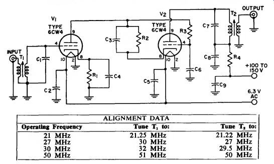
For 15-, 10-, and 6-Meter (21-, 30-, and 50-MHz)
Amateur Bands and 27-MHz Citzens Band
Circuit Description
In this preamplifier, two 6CW4 high-mu nuvistor triodes are used in a high-gain, low-noise cascode rf amplifier stage that adds 25 to 35 dB of gain ahead of a receiver operated on the 6-, 10-, or 15-meter amateur band or on the 27-MHz citizens band.
This added gain, together with the low noise figure (approximately 5 dB) of the preamplifier, substantially increases both the sensitivity and the signal-to-noise ratio of the receiver.
The preamplifier operates from a dc plate supply of 150 volts at 5 milli amperes. The tube heaters require an ac power input of 6.3 volts at 0.26 ...
------------------
Parts List
C1, Oi- See Note 1 Cs, Ca, C1, Cs, Ca, Cs, C«=0.001 uF, 600 V, ceramic El, Ra=100 ohms, 0.6 watt Ri=0.47 megohm, 0.6 watt R<=1000 ohms, 0.6 watt T1= Input transformer (slug tuned) ; matches preamplifier to 62-ohm input line (for 300-ohm input line, double number of turns in primary) ; wound from #32 copper enamel wire on slug tuned form having %-inch outer diameter : primary, 1% turns ; secondary, 18 turns for operation at 21, 27, or 30 MHz or 10 turns for operation at 60 MHz Ts=0 u t p u t transformer (slug-tuned) ; matches pre amplifier to 72-ohm output lines (use of other than a 72-ohm line between pre amplifier output and receiver input is not recommended) ; wound from #32 copper enamel wire on slug tuned form having %-inch outer diameter ; primary, 18 turns for operation at 21, 27, or 30 MHz or 10 turns for operation at 60 MHz, secondary, 1% turns.
Notes: 1. For operation at 21 or 27 MHz, use 6.8-pF 500-volt capacitors for C1 and C7; for operation at 30 MHz, use 6-pF 500-volt capacitors for C1 and Cv ; for operation at 60 MHz, use 5-pF 500-volt capacitor for C1 and 6.8-pF 600-volt capacitor for C7.
2. See general considerations for construction of high-frequency and broadband circuits on page S7G.
-----------------------
... ampere. These small power requirements can usually be provided by the receiver.
Input transformer Tx matches the high input impedance of the pre amplifier to a 72-ohm or 300-ohm antenna. When a 72-ohm antenna is used, the primary of Ti consists of a 1 1/2-turn link wound about the hot end of the secondary coil. For a 300 ohm antenna, a 3-turn link is used.
The secondary of Ti is an 18-turn coil for operation at 10 or 15 meters or on the citizens band. At 6 meters, a 10-turn secondary coil is used. The unit is normally connected to the antenna cable by means of a coaxial connector. If a balanced antenna system is used, however, terminal strips for the twin leads may be used instead of the coaxial connector. In this latter case, the input link (primary of T1) is not grounded.
Nuvistors V1 and V2 are operated in a stacked (cascode) arrangement in series with the B+ supply. The input is coupled by T1 to the control grid of V1, which is essentially a grounded-cathode amplifier. The out put of V1 is applied to the cathode of V2, which is basically a grounded grid amplifier. The inherent stability of this type of arrangement, together with the ample decoupling and by passing networks included in the circuit, provides assurance that the preamplifier will not break into oscillation.
The output of V1 is developed across the primary coil of output transformer Ts. This coil is identical to the secondary coil of input transformer T1. The secondary of Tt consists of a 1.5-turn link about the primary coil. This link matches the output of the preamplifier to a 75-ohm receiver input cable. (The maximum length of coaxial cable between receiver and preamplifier should not exceed 12 inches.)
29-7 CODE-PRACTICE OSCILLATOR
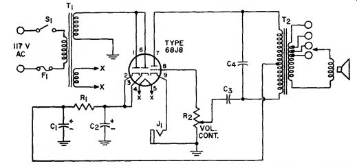
Note : Any two terminals of the secondary of Tz that give the desired tone may .be selected. Adjustment of volume control may cause a slight change in tone.
Parts List
C1, C2=20 uF, electrolytic, 160 V
Cs=0.001 uF, paper, 200 V
C1=0.03 pfe, paper, 200 V
F=% ampere
Ji=Input jack for key
R1=lB00 ohms, 1 watt
R»=Potentiometer, 0.1 megohm, 0.5 watt
Ti=Power transformer, 125 volts rms, 15 ma ; 6.3 volts,
0.6 ampere
T1*=Output transformer, universal
Circuit Description
This code-practice oscillator operates from a 117-volt ac power line.
When ON-OFP switch S1 is closed, the 117-volt ac input power is stepped up to 125 volts across the upper secondary winding of power transformer T1 and is stepped down to 6.3 volts across the lower secondary winding.
The 6.3-volt winding provides the operating power for the heater of the 6BJ8 twin diode-triode used in the circuit. The diode sections of the 6BJ8 are connected to operate as a single diode in a half-wave rectifier circuit that converts the ac power across the 125-volt winding of T1 to dc operating power for the 6BJ8 triode section.
This triode section is used as the amplifier tube in a simple audio-oscillator stage.
Operation of the oscillator stage is controlled by a telegraph key, which is connected into the circuit by means of jack J1. When the key is closed, the triode section of the 6BJ8 supplies energy to the oscillator resonant circuit formed by capacitor d and the effective inductance of the primary of output transformer T1.
This circuit then resonates to pro-duce an audio signal that is coupled by transformer T3 to the speaker to produce an audible indication of the keying. Positive feedback to sustain oscillation is developed by the auto transformer action of the tapped primary of transformer T2.
Output transformer T2 is a universal type which contains multiple taps on the secondary winding. These taps enable the transformer to match the oscillator output impedance to different values of speaker voice-coil impedance. The speaker impedance and transformer terminals used, how ever, affect the effective inductance in the primary of T1 and, thus, the tone of the audio output. Volume control potentiometer R2 adjusts the level of the audio output. Adjustment of potentiometer R2 varies the loading on the oscillator resonant circuit and may also cause a slight change in the tone of the audio output.
29-8 INTERCOMMUNICATION SET
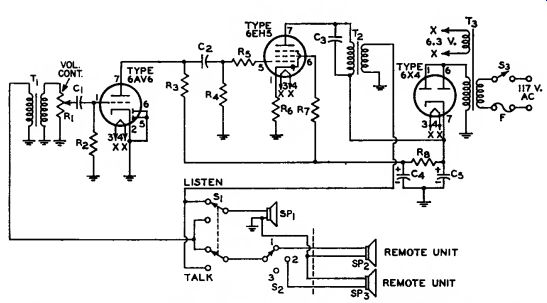
With Master Unit and Two or More Remote Units
Notes: 1. The leads from the LISTEN-TALK switch S1 to T1 and T2 should be kept as far apart as possible to prevent undesirable regenerative effects.
2. Connections to the remote speaker units should be made with low-resistance wire, preferably with shielded "intercom" cable.
Parts List
C1. C2=0.0022 uF. paper, 200 V.
Cj=0.005 nT, paper, 200 V.
C«, C5=60 uF, electrolytic, 150 V.
Fi=Fuse, 1 ampere Ri=Volume control, potentiometer, 0.6 megohm, audio taper, attached to switch Ss R2=6.8 megohms, 0.5 watt
So, Rj=0-47 megohm, 0.5 watt
Ru=10000 ohms, 0.5 watt
Re, R7=68 ohms, 0.5 watt
Rs=2200 ohms, 1 watt
S1=Talk-listen switch, double-pole, double-throw
S2=Station Selector, rotary switch Sa=On-off switch, single-pole, single-throw ,* attached to volume-control potentiometer
SP1, SP2, SP3=Speaker ; permanent-magnet ; voice-coil impedance, 3 to 4 ohms
T1=Input transformer, 4-ohm primary, 25000-ohm secondary. Knight 54A1492 or equiv.
Ts=Output transformer, 3000 ohm primary, 4-ohm secondary, Knight 54A2371 or equiv.
Ta=Power transformer, 125 volts rms, 50 mA., 6.3 volts rms. 2 amperes, Knight 54A1411 or equiv.
Circuit Description
This simple "intercom" set can be used to achieve reliable voice communications, at normal speaking levels, between any two points in a normal-size house. The system consists of a master unit, centrally located at the hub of household activity, interconnected by low-loss cabling to remote units located at points (e.g., garage, attic, and cellar) beyond the range of normal voice levels. An audio amplifier, which includes a 6AV6 voltage-amplifier stage and a 6EH5 power-output stage, provides the amplification necessary to overcome the attenuation of voice levels by system cabling. A 6X4 half-wave rectifier circuit converts the 117-volt ac input power to the dc power required for operation of the amplifier stages. A 6.3-volt secondary winding on the power transformer(T3 ) in the rectifier circuit provides heater power for the amplifier and rectifier tubes.
The speaker at each intercom station is used for both talk and listen functions. The talk-listen switch S1 at the master location establishes the talk or listen mode for all stations. The voice communications are initiated from the master unit. Switch S1 is depressed to the TALK position, and the initiator talks into the master-unit speaker. The audio (voice signal) voltage that is then developed across the speaker voice coil is coupled by input transformer Ti to the control grid of the 6AV6 audio amplifier. Selector switch Ss connects the desired remote unit into the intercom system. With S1 depressed to the TALK position, the remote unit speaker is automatically connected to the audio amplifier output for listen-mode operation. When S1 is in the LISTEN position, the master-unit speaker is connected in the listen mode, and the remote-unit speaker is connected to the amplifier input. A reply from the remote unit is then coupled from the remote speaker by transformer T1 to the control grid of the 6AV6 audio amplifier.
Transformer T1 matches the voice-coil impedance of the 4-ohm permanent-magnet speaker (of either master or remote unit) to the 25000 ohm input impedance of the 6AV6 amplifier stage. This stage and the 6EH5 audio output stage amplify the audio (voice) signals received from one location (the master unit or one of the remote units) to develop the audio power required to produce an audible output from the speaker at another location. Output transformer T3 matches the 3000-ohm plate-circuit impedance of the output stage to the 4-ohm voice-coil impedance of the speaker (master-unit or remote-unit) to which the communication is directed, as determined by the settings of switches S1 and S2. The VOL. CONT. potentiometer Ri in the input circuit of the 6AV6 audio amplifier stage provides the volume-control adjustment for the system.
29-9 HIGH-FIDELITY AUDIO AMPLIFIER
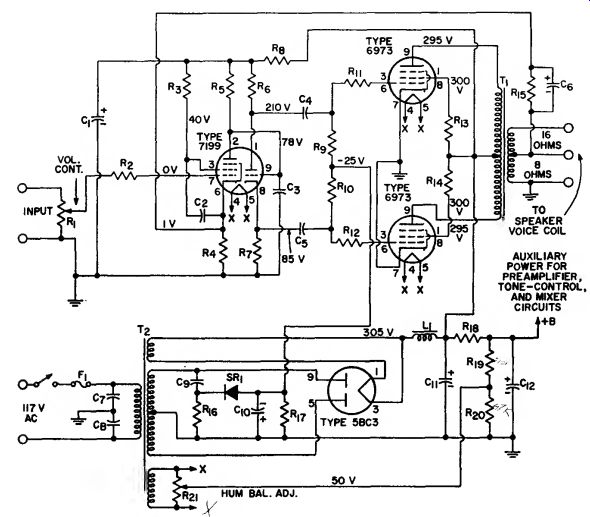
Class AB1; Power Output, 15 Watts
Circuit Description This high-fidelity audio power amplifier can deliver 15 watts of rms output power with less than 0.4 percent total harmonic distortion and less than 1.5 percent intermodulation distortion. The frequency response of the amplifier is flat within ±0.5 dB from 20 Hz to 60 kHz, and the sensitivity is such that the rated output of 15 watts is obtained for an input of 1.2 volts rms. The total hum and noise, with the input shorted, is 84 dB below 15 watts. The circuit operates from a 117-volt ac power line.
The transformer-coupled ac input power is converted to dc operating ....
--------------------------------------
Parts List
C1=40 uF, electrolytic, 450 V.
C1, C1, Cs=0.26 uF, paper, 400 V.
Cs=3.3 pF, ceramic or mica, 600 V.
C«=150 pF, ceramic or mica, 400 V.
Ct, Cs=0.06 uF, paper, 400 V.
C»=0.02 uF, paper 600 V.
C»=100 uF, electrolytic, 60 V.
C1i=80 uF, electrolytic, 460 V.
C1a=40 uF, electrolytic, 450 V.
F1=Fuse, 3 amperes
L1=Choke, 3 H, 160 mA, dc resistance 75 ohms or less, Triad C-13X or equiv.
R1=Volume control, potentiometer, 1 megohm
R2=10000 ohms, 0.6 watt Rs=0.82 megohm, 0.5 watt
R1=820 ohms, 0.6 watt Rs=0.22 megohm, 0.5 watt
Ro, R7=15000 ohm ±5 percent, 2 watts
Rs=3900 ohms, 2 watts Ri>, Rio=0.1 megohm,
0.5 watt Hit, Ris=1000 ohms, 0.5 watt
Ri=, Rw=100 ohms, 0.5 watt
Ru=8200 ohms, 0.5 watt
Rio=15000 ohms, 1 watt
Ri7=68000 ohms, 0.5 watt
Ri8=4700 ohms, 2 watts
Rib-0.27 megohm, 1 watt
Rl>o=47000 ohms, 0.5 watt
Rsi=Hum balance adjustment, potentiometer, 100 ohms, 0.5 watt
SR1=Selenium rectifier, 20 mA, 135 volts rms
Ti=:Output transformer, (having 8-ohm tap for feed back connection) for matching impedance of voice coil to 6600-ohm plate-to-plate tube load ; 60 watts ; frequency response, 10 to 50000 Hz ; Stancor A-8056 or equiv.
T2=Power transformer, 360-0-360 volts rms, 120 mA ; 6.3 V., 3.5 A ; 5 V., 3 A ; Stancor 8410 or equiv. (see Note 1)
Notes:
1. For stereo operation from a single power supply, the power transformer Ts must be replaced by one that has a higher current rating. A Stancor Type 6315 or equivalent (370-0-370 volt rms, 275 mA) is recommended.
2. If the amplifier oscillates or "motorboats," reverse ground and feedback connections in secondary of output transformer T1.
----------------------------
power for the amplifier stages by the 5BC3 full-wave rectifier. Heater power for the amplifier tubes and the rectifier are obtained from the 6.3 volt and 5-volt secondary windings, respectively, on the rectifier power transformer (T2 ).
A high-gain pentode voltage amplifier is used as the input stage for the audio power amplifier. The output of this stage is direct-coupled to the control grid of a triode split load type of phase inverter. The use of direct coupling between these stages minimizes phase shift and, consequently, increases the amount of inverse feedback that may be used without danger of low-frequency in stability. A low-noise 7199 tube, which contains a high-gain pentode section and a medium-mu triode section in one envelope, fulfills the active-component requirement for both the pentode input stage and the triode phase inverter. Potentiometer R, in the input circuit of the 7199 pentode section is the volume control for the amplifier.
The plate and cathode outputs of the phase inverter, which are equal in amplitude and opposite in phase, are used to drive a pair of pentode-connected 6973 beam-power tubes used in a class AB1 push-pull output stage.
The 6973 output tubes are biased for class AB1 operation by the fixed negative voltage applied to the control grid circuit from the rectifier circuit.
Fixed bias is used because a class AB amplifier provides highest efficiency and least distortion for this bias method.
Transformer T1 couples the audio amplifier output to the speaker. The taps on the secondary of this transformer match the plate-to-plate impedance of the output stage to the voice-coil impedance of an 8- or 16 ohm speaker. Negative feedback of 19.5 dB is coupled from the secondary of the output transformer (speaker voice coil) to the cathode of the input stage to reduce distortion and to im prove circuit stability.
Fixed-bias operation of the out put stage requires that the power supply provide very good voltage regulation because the plate current of the 6973 tubes varies considerably with the signal level. The conventional choke-input type of power supply used provides the required regulation. The fixed bias for the out put stage is obtained from one-half the high-voltage secondary winding of power transformer T- through a capacitance-resistance voltage divider and the 20-milliampere, 135-volt selenium rectifier. Potentiometer Rn connected across the 6.3-volt second ary winding of transformer T2 provides a hum balance adjustment for the audio power amplifier. The wiper arm of this potentiometer is connected to the junction of a resistive voltage divider across the output of the power supply. The resulting positive bias voltage applied to the tube heaters minimizes heater-to-cathode leakage and substantially reduces hum.
29-10 Circuit Description
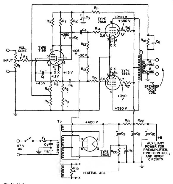
HIGH-FIDELITY AUDIO AMPLIFIER Class AB1; Power Output, 30 Watts
This audio power amplifier can deliver 30 watts of rms output power with less than 0.7 percent total harmonic distortion and less than 1.5 percent intermodulation distortion.
The frequency response of the amplifier is flat within ±0.5 dB from 15 Hz to 40 kHz. The total hum and noise, with the input shorted, is 85 dB below 30 watts. The rated output of 30 watts is obtained for an input of 1 volt rms.
-----------
Parts List
C1=25 uF, electrolytic, 50 V C->=22 pF, ceramic or mica, 600 V C3=80 jiF, electrolytic, 450 V Oi, O.=0.n5 uF, paper, 600 V C«=0.01 uF, paper, 600 V C7, Cs^O.05 uF, paper, 600 V C», Cn=40 uF, electrolytic, 500 V C1o=100 uF, electrolytic, 50 V C12=20 nF, electrolytic, 450 V Fi=Fuse, 3 amperes, 150 V Ri=r
Volume control, potentiometer, 1 megohm
Ri>=10000 ohms, 0.5 watt
Rx=0.22 megohm, 0.5 watt
Rj=820 ohms, 0.5 watt
Rs=10 ohms, 0.5 watt
Ro=0.18 megohm, 0.5 watt
Rt, Rs=15000 ohms ±5 percent, 2 watts R9=1000 ohms, 0.5 watt Rio=22000 ohms, 0.5 watt Rii=2000 ohms, 2 watts Ris, Ria=0.1 megohm, 0.5 watt Rn, Ri5=1000 ohms. 0.5 watt Ri«, R17-56 ohms, 0.5 watt Ris=270 ohms, 0.5 watt Rio=Hum balance adjust ment, potentiometer, 100 ohms, 0.5 watt R2o=220 ohms, 10 watts R2i=50 ohms, 10 watts R =10000 ohms, 2 watts Ti=Output transformer (having 16-ohm tap for feedback connection) for matching impedance of voice coil to 6600-ohm plate-to-plate tube load ; 50 watts ; fre quency response, 10 to 50000 Hz ; Stancor A-8056 or equiv.
T==Power transformer, 375-
0-375 volts rms, 160 mA ;
6.3 V., 5 A ; 5 V., 3 A ;
Thordarson type T22R33 or equivalent (see Note 1).
----------------
Notes: 1. For stereo operation from a single power supply, the power transformer TV must be replaced by one that has a higher current rating. A Stancor Type 6315 or equivalent (370-0-370 volts rms, 275 mA) is recommended.
2. If amplifier oscillates or "motorboats," reverse ground and feedback connections in secondary of output transformer Ti.
-----------------
The 30-watt amplifier is essentially identical to the 15-watt amplifier (circuit 29-9) except that it uses 7868 beam power tubes in the out put stage to develop the higher audio power output and uses a resistive network in the negative leg of the power supply, rather than a separate rectifier, to supply the fixed-bias voltage for the output stage. A potentiometer (Ru) connected across the 6.3-volt heater winding also provides the hum balance adjustment for the 30-watt amplifier.
29-11 HIGH-FIDELITY AUDIO AMPLIFIER
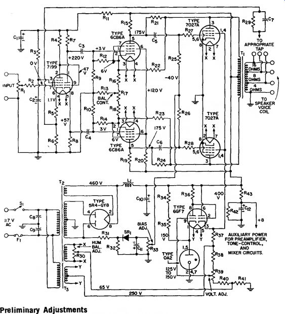
Class AB1; Power Output, 50 Watts
Preliminary Adjustments The following adjustments should be mode before operation:
(1) With rectifier out of socket, adjust Bias Adj. Ra3 for -40 volts between the wiper arm and ground bus.
(2) With speaker connected, adjust Screen-Grid Voltage Adj. Rsa for 400 volts between pin 3 of 6GF7 and ground bus.
(3) With input shorted, adjust Hum Bal Adj. Ba> tor minimum hum from speaker.
(4) With input open and Vol. Cont. set for maximum volume, adjust Bal. Cont. R17 for minimum hum from speaker.
Parts List
C1, C«=40 uF, electrolytic, 460 V Cs, C4=0.02 /»F, paper, 400 V C», Cn=1uF, paper, 400 V C7=0.002 uF to 4-ohm tap
0.0015 nF to 8-ohm tap ; or, 0.001 uF to 16-ohm tap ; paper, 400 V Cs, C»=0.05 uF, paper, 600 V Cu>=20 uF, electrolytic, 450 V Cu=100 uF, electrolytic, 160 V C12=40 uF, electrolytic, 450 V
F1=Fuse, 5 amperes
L1=Choke, 8 H, 250 mA, dc resistance 60 ohms, or less
R1=Volume control, potentiometer, 0.5 megohm
R2=4700 ohms, 0.6 watt
R3=0.82 megohm, 0.6 watt
R4=0.22 megohm, 0.6 watt
Rb=820 ohms, 0.5 watt
Ra=10 ohms, 0.5 watt R? Rs= 16000 ohms, 2 watts
R», RiD=1.5 megohms,
0.5 watt Rii=33000 ohms, 2 watts
Rij, Ru=1.3 megohms,
0.5 watt Ri3=47 ohms, 0.5 watt
Riii. Ri»=0.15 megohm,
0.5 watt Rie, Ris=390 ohms, 0.5 watt
Ri7=AC balance control, potentiometer, 500 ohms
Ri>o=0.15 megohm, 1 watt Ka, R24=0.33 megohm, 1 watt
R22. Rs3=0.12 megohm, 2 watts
R2.1, R2e=0.1 megohm,
0.5 watt R27, R28=4700 ohms,
0.5 watt Rii>-600 ohms to 4-ohm tap :
820 ohms to 8-ohm tap ; or, 1200 ohms to 16-ohm tap
0.5 watt Raa=Hum balance adjustment, potentiometer, 100 ohms Rm=0.12 megohm, 6 watts R32, R.K, Ran, R»7=33000 ohms. 2 watts R33=Bias adjustment, potentiometer 50000 ohms, Rm=0.27 megohm, 0.5 watt R3s=10000 ohms, 1 watt Rss=Screen-grid voltage adjustment, potentiometer, 25000 ohms, 2 watts R«o=16000 ohms, 2 watts R«=12000 ohms, 2 watts R«=0.22 megohm, 2 watts R,3=22000 ohms, 2 watts
SRi=Selenium rectifier, 20 mA, 135 volts rms
T1=Output transformer for matching impedance of voice coil to 5000-ohm plate-to-plate tube load ; 50 watts ; frequency response, 10 to 60000 Hz; United Transformer Corp.
LS6L4 or equiv. (see Note 1)
Tz=Power transformer, 600-0-600 volts rms, 200 mA, 6.3 V., 5 A ; 5 V., 3 A : ThoH--- "2R36 or equiv. (see Note 2)
T3=Filament transformer, 6.3 volts, center tapped, 1 ampere ; Thordarson 21F08 or equiv.
Notes:
1. In many applications less expensive transformers. such as Stancor Type A8053 narrower frequency or United Transformer Corporation Type S-17, which have response, may be used for T1 with satisfactory results.
2. For stereo operation from a single power supply, the following changes are required : (a) The power transformer T2 must be replaced by one that has a higher current rating; a Freed Transformer Corporation Type DC6A or equivalent (600-0-600 volts rms, 300 mA) is recommended, (b) The 60000-ohm Bias Adj. potentiometer R33 should be replaced by two 100000-ohm potentiometers (one for each channel) connected in parallel, (c) A second 5R4-GYB rectifier tube should be connected in parallel with the one used for monaural operation. (Connect the 5R4-GYB tubes so that the two sections of each tube are in parallel with the corresponding sections of the other tube ; do not use separate tubes for each section of the rectifier circuit.)
3. If the amplifier oscillates or "motorboats," reverse ground and feedback connections in secondary of output transformer T1.
Circuit Description
This four-stage audio power amplifier can deliver 50 watts of rms power output with less than 0.1 percent total harmonic distortion and less than 1 percent intermodulation distortion. The frequency response of the amplifier is flat within ±0.5 dB from 10 Hz to 50 kHz. Sensitivity is 0.4 volt rms input for 50 watts output. The total hum and noise is 70 dB below 50 watts.
The 50-watt amplifier, like the 15-watt and 30-watt high-fidelity amplifiers (circuits 29-9 and 29-10), uses a 7199 low-noise triode-pentode as an input amplifier and phase splitter, but has a push-pull driver stage, which uses 6CB6 sharp-cutoff pentodes. The superior performance of this amplifier can also be attributed, in part, to the use of a 450-volt plate supply and a 400-volt electronically regulated grid-No. 2 supply for the 7027A beam power tubes in the output stage and to the use of inverse-feedback loops from the plates to the grids of the output tubes, from the plates of the output tubes to the cathodes of the driver tubes, and from the voice-coil winding of the output transformer to the cathode of the input amplifier. Additional features are the operation of all heaters at a positive voltage with respect to ground and use of a balancing adjustment (R») in the heater-supply circuit to minimize hum, a grid-No. 2 voltage adjustment (Rsn), a grid-No. 1 bias adjustment (Rb) for the 7027A output tubes, and an ac-balance adjustment (Ris) which may be used to balance the outputs of the push pull stages. Operation of the 50-watt amplifier is essentially the same as that of the 15- and 30-watt amplifiers.
29-12 TWO-CHANNEL STEREOPHONIC AMPLIFIER
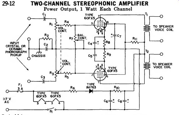
Power Output, 1 Watt Each Channel
Parts List
C1, Co=0.22 uF, paper.
400 V C2=0.1 uF, paper, 400 V
C1. Cs=50 uF, electrolytic, 25 V C«=50 uF, electrolytic, 150 V Ct, C8=60 uF .electrolytic, 150 V Fi=Fuse, 3 amperes
Ri, R:i ~ Volume control potentiometer, 1.5 megohms, ganged, audio taper Rj = 0.22 megohm, 0.5 watt
Ri, Rr. = 47000 ohms, 0.5 Rn = 12 ohms, 1 watt
R7 = Balance control, potentiometer, 2 megohms, audio taper
Rs, Ru = 60 ohms, 1 watt
Riu = 280 ohms, 2 watts
Rn = 220 ohms, 2 watts
S1 = ON-OFF switch, single pole, single-throw
Ti, Ta ~ Output transformer for matching impedance of voice coil to 3000-ohm tube load ; Triad S-16X or equiv.
Circuit Description
This ac/dc two-channel (stereo) amplifier operates from either an ac power line or dc supply of 117 volts.
AC power inputs are converted to dc power by the 1N1763 silicon-diode half-wave rectifier circuit. The heaters of the 60FX5 power pentodes (one for each channel) used in the amplifier are connected in series directly across the input power line.
In stereo units that use high output ceramic stereo cartridges, the high power sensitivity of the 60FX5 tubes at low supply voltage eliminates the need for preamplifier stages. The 60FX5 provides a power output of 1.3 watts to a 3000-ohm transformer primary with only 3 volts peak drive on grid No. 1. With a transformer having a good impedance match and 85-percent efficiency, each channel of the stereo amplifier supplies 1.1 watts of useful power output at the speaker.
No special mounting or layout precautions are necessary for this amplifier other than the value and placement of the isolating capacitor C4 between B- and the chassis. This capacitor should be connected to the same point on the chassis at which the common cartridge lead is tied.
A value of 0.1 microfarad for the isolating capacitor is suggested so that full output is obtained from the pickup.
As with all single-ended amplifier circuits, especially ac/dc units, adequate screen-grid bypassing is necessary to minimize hum. Screen grid filtering is obtained through use of a 220-ohm dropping resistor Rs and a 50-microfarad electrolytic capacitor C1. Although, in the circuit shown, separate cathode-bias resistors are used for better dynamic balance, a single 30-ohm common cathode-bias resistor bypassed with a 50-micro farad electrolytic capacitor may also be used.
29-13 MICROPHONE AND PHONOGRAPH AMPLIFIER
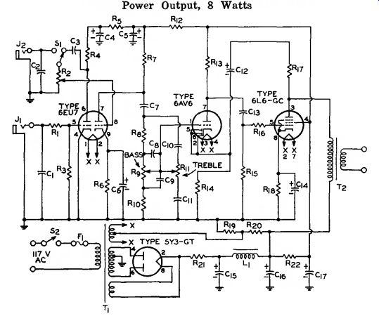
Power Output, 8 Watts
Parts List
C1, C2=100 pF, disc-ceramic, 300 V
Ca=O.0S nF, paper, 200 V
C1=8 uF, electrolytic, 450 V
Cs=16 pF, electrolytic, 450 V C«=25 uF, electrolytic, 450 V
Cj=0.1 aF, paper, 200 V Cs=0.001 uF, disc-ceramic, 300 V
Co=0.01 uF, disc-ceramic, 300 V C1o=470 pF, disc-ceramic, 300 V Cn=4700 pF, disc-ceramic, 300 V C12=4 uF, electrolytic, 450 V C13=0.05 pF, paper, 600 V C1»=25 uF, electrolytic, 25 V C1s, Cw, Cu=:20 uF, electro lytic, 450 V Fi=Fuse, 1 ampere Ji=Jack for high-impedance crystal microphone input max. input: 2 millivolts peak Ji*=Jack for crystal phono pickup input Li=Filter choke, 5 H, 200 mA, United Trans former Corp. R20 or equiv.
Ri, Rm=10000 ohms, 0.5 watt R1
Volume Control, potentiometer, 1 megohm
R:i=2.2 megohms, 0.5 watt
Ri, Rs, Rai=0.22 megohm, 0.5 watt
Ra=27000 ohms, 0.5 watt
Ro=1200 ohms, 0.5 watt
R-, Ri3=0.1 megohm, 0.5 watt
Ro, Rn=Tone control, potentiometer, 0.5 megohm
Rio=22000 ohms, 0.6 watt
Ri2=12000 ohms, 0.5 watt
Ru=1800 ohms, 0.5 watt
Ri5=0.47 megohm, 0.5 watt
Ri7=0.15 megohm, 0.5 watt
Ris=180 ohms, 2 watts
Rio=47000 ohms, 1 watt
R2i=50 ohms, 10 watts
Ra2=8200 ohms, 2 watts
Si=Microphone-phonograph selector ; wafer switch ; single-pole, double-throw
S2=ON-OFF switch, single pole, single-throw
T1=Power transformer, 300-0-300 V., 90 mA. ; 6.3 V., 3.5 A., center tapped ; 5 V., 2 A, Thordarson 22R04 or equiv.
Ti'^
Output transformer for matching impedance of voice coil to 4000-ohm tube load ; 10 watts ; United Transformer Corp. S14 or equiv.
Circuit Description
This microphone and phonograph amplifier can deliver up to 8 watts of audio output power for an input of 200 millivolts rms at J2 (phonograph input) or an input of 6.8 millivolts rms at Ji (microphone input). The amplifier uses a 6EU7 twin-triode input amplifier, a 6AV6 driver stage, and a 6L6GC single-ended output stage to increase the signal power from a high-impedance crystal microphone or crystal phonograph pickup to the desired level. The transformer coupled ac input power is converted to dc operating power for these stages by a 5Y3GT full-wave rectifier circuit. A 5-volt winding on power transformer T1 provides the heater power for the rectifier tube, and a 6.3-voIt winding provides heater power for the other tubes in the amplifier. The center tap on the 6.3-volt winding is connected to the junction of a resistive voltage divider (Rn. and Rm) across the output of the power supply. The resulting positive bias applied to the tube heaters substantially reduces heater-to-cathode leakage and, consequently, minimizes' hum.
The signals from a crystal micro phone are usually much smaller than those from a crystal phonograph pickup. Microphone signals, there fore, are amplified by both sections of the 6EU7 twin-triode amplifier.
The signals are coupled from J1 to the pin 5 control grid of the 6EU7.
The plate output from this triode section is then coupled through switch S1 (microphone position) and volume-control potentiometer R2 to the pin 8 control grid of the 6EU7.
With selector switch S1 in the phono graph position, phonograph inputs are coupled directly from J2 across volume-control potentiometer R2 to the pin 8 control grid, and the first section of the 6EU7 is bypassed.
The outputs from the pin 7 plate of the 6EU7 are coupled across the frequency-sensitive tone-control net work to the control grid of the 6AVG driver stage. The bass and treble controls R» and Rn are adjusted to assure optimum low- and high-frequency response characteristics for the amplifier. The two diode plate sections of the 6AV6 are shorted to the tube cathode and thereby are made inoperative. The output of the driver stage is applied to the 6L6GC output stage which develops the audio power required to drive a speaker. Transformer T» matches the 4000-ohm plate impedance of the out put stage to the speaker voice-coil impedance.
9-14 TWO-CHANNEL AUDIO MIXER
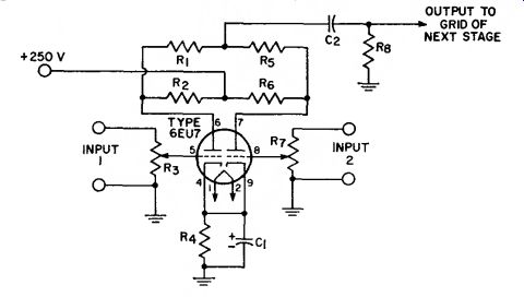
Voltage Gain from Each Grid of 6EU7 to Output is Approximately 20
Parts List
C1=10 «F, electrolytic, 25 V C2=0.05 uF, paper, 400 V R1, Rn, Rs=1 megohm,
0.5 watt R-2 Ro=0.1 megohm,
0.5 watt
R3, R7=Potentiometers, 0.1 megohm, audio taper
R1=1200 ohms, 0.5 watt
Circuit Description
This high-fidelity mixer circuit can be used to combine audio-frequency program material from two sources. Each signal channel consists of a one-stage voltage amplifier using one section of a 6EU7 low noise twin-triode. Each section of the mixer can provide a voltage gain of about 20, and can handle an input signal of about 0.2 volt rms without overloading. The dc plate supply of +250 volts (nominal value) for the mixer stages can usually be obtained from an auxiliary tap on the power supply for the audio power amplifiers.
29-15 PHONOGRAPH AMPLIFIER
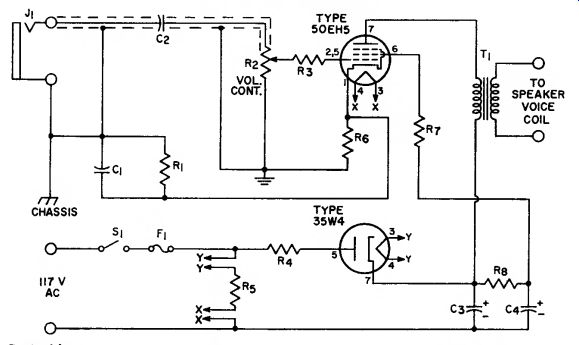
Power Output, 1 Watt
Parts List
C1=0.082 uF, paper, 400 V C2=0.02 pF, paper, 400 V
Ca, C*=40 uF, electrolytic, 160 V
F1=Fuse, 1 ampere
J1=Input connector, shielded, for crystal phonograph pickup R1=0.22 megohm, 0.5 watt
R1=Volume control, potentiometer, 0.5 megohm, audio taper R:i=10000 ohms, 0.5 watt R<=22 ohms, 0.5 watt Ro=210 ohms, 10 watts R.i, R-=56 ohms, 0.5 watt Rs=3300 ohms, 1 watt
T1=Output transformer for matching impedance of voice coil to 3000-ohm tube load
Circuit Description
This single-stage phonograph amplifier operates directly from either an ac power line or a dc supply of 117 volts. AC power inputs are converted to dc power by the 35W4 half-wave rectifier circuit. The heaters of the amplifier and rectifier tube are connected in series, together with a 210-ohm voltage-dropping resistor, Rs, directly across the input power line.
The amplifier uses a 50EH5 power pentode to develop up to 1 watt of audio output power from the input supplied from a crystal phono graph pickup. The input is applied at J1 and coupled through a length of shielded cable to the input circuit of the pentode amplifier. Volume-control adjustment for the amplifier is provided by potentiometer R». The out put coupling transformer T1 matches the 3000-ohm plate load impedance of the 50EH5 to the voice-coil impedance of the speaker.
29-16 PREAMPLIFIER FOR MAGNETIC PHONOGRAPH PICKUP
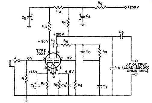
With RIAA Equalization
Sensitivity=3 millivolts rms input for output of 0.55 volt at frequency of 1000 Hz.
Parts List
C1, C<=25 u-F, electrolytic, 25 V Cs, Cs=20 uF, electrolytic, 450 V C3=0.1 *»F, paper, 600 V Co=0.0033 uF±5 percent, paper, 600 V Ct=0.01 uF±S percent, paper, 600 V Cs=180 pF±5 percent, ceramic or mica, 500 V (includes capacitance of output cable) Co=0.22 ^iF, ceramic, 500 V J=Input connector, shielded, for high-impedance magnetic phono pickup (10 mV output, approx.) Ri=Value depends on type of magnetic pickup used.
Follow pickup manufacturer's recommendations R*, R7=2700 ohms, 0.5 watt
R.i, R»=0.1 megohm, 0.5 watt
Rj=39000 ohms, 0.5 watt
Re-0.47 megohm, 0.5 watt
Rs=:0.68 megohm, 0.5 watt
Ro=15000 ohms, 1 watt
Rio=:22000 ohms, 0.5 watt
Circuit Description
This two-stage audio preamplifier is intended for use with high-fidelity magnetic phonograph pickups. The two amplifier stages provide an over all circuit gain of approximately 150.
The 7025 twin triode used in the circuit features exceptionally low hum and noise and is designed especially for use in high-fidelity circuits that operate at low signal levels. The preamplifier is ideally suited for use as the low-level input stage for audio power amplifiers such as the 50-watt unit, circuit 29-11. For use with audio power amplifiers such as the 15- and 30-watt units, circuits 29-9 and 29-10, which require higher input signals, another low-level amplifier (e.g., the tone-control amplifier, circuit 29-20) must be inserted between the preamplifier and the power amplifier to obtain the full rated output. The heater and dc operating power required for the pre amplifier can usually be obtained from the power-supply circuit for the power amplifier.
The audio signal from the phono graph pickup is applied to J and coupled through a length of shielded cable to the control grid of the input stage of the preamplifier. The inter stage coupling between the two amplifier sections of the preamplifier includes an RIAA equalization net work (Ri. and Co). This network compensates for the Orthophonic recording characteristic introduced into a record disc by the manufacturer. The output from the preamplifier is coupled from the plate of the second stage by output coupling capacitor C. to the input of a tone-control amplifier (if used) or directly to the input of the power amplifier. Because of its relatively high output impedance, the preamplifier is recommended for use in systems in which the preamplifier is mounted on the same chassis as the power amplifier and/or tone-control amplifier. The preamplifier may be used at distances up to 6 feet from the following amplifier provided that the capacitance of capacitor Cs is reduced approximately 30 picofarads for each foot of shielded cable used for the audio frequency connection between the preamplifier and the following amplifier.
To achieve wide frequency and dynamic ranges, manufacturers of commercial recordings use equipment which introduces a non-uniform relationship between amplitude and frequency. This relationship is known as a "recording characteristic." To assure proper reproduction of a high fidelity recording, therefore, some part of the reproducing system must have a frequency-response characteristic which is the inverse of the recording characteristic. Most manufacturers of high-fidelity recordings use the RCA "New Orthophonic" (RIAA) characteristic for discs and the NARTB characteristic for magnetic tape.
29-17 HIGH-FIDELITY PREAMPLIFIER FOR TAPE-HEAD PICKUP
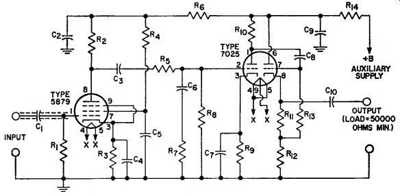
With NARTB Equalization
Sensitivity=3 millivolts rms input for output of 0.55 volt at frequency of 1000 Hz.
Parts List
C1=0.047 uF, ceramic, 400 V
Cs=40 uF, electrolytic, 450 V
C3=0.1 u-F, ceramic, 400 V C<=25 u-F, electrolytic, 25 V C5=0.22 uF, ceramic, 400 V C«=0.015 uF, ceramic, 400 V C7=25 ^F, electrolytic, 25 V Cs=0.22 uF, ceramic, 400 V Co=40 uF, electrolytic, 450 V C1o=0.47 #F, ceramic, 400 V Ri-1 megohm, 0.5 watt R2=0.1 megohm, 0.5 watt
Rj=1000 ohms, 0.5 watt
R^rrO.47 megohm, 0.5 watt
Rs=0.22 megohm, 0.5 watt
R6=22000 ohms, 0.5 watt
R7=3300 ohms, 0.5 watt
Rs=3.3 megohms, 0.5 watt
Ro=1500 ohms, 0.5 watt
Rio=0.1 megohm, 0.5 watt
Rn=1500 ohms, 0.5 watt
Ri2=15000 ohms, 0.5 watt
Ri3=0.47 megohm, 0.5 watt
Ri<=4700 ohms, 0.5 watt
Circuit Description
This three-stage preamplifier provides the amplification necessary to increase the output from a tape head pickup to the level required to drive an audio power amplifier. The circuit uses a 5879 low-noise sharp cutoff pentode in a high-gain input voltage amplifier, one section of a 7025 twin triode in a second voltage amplifier, and the other section of the 7025 in a cathode-follower output stage. Because of the low-impedance cathode-follower output circuit, the preamplifier may be installed at distances up to 50 feet from the following stage (tone-control or power amplifier) without adverse effect upon its frequency-response characteristics. The preamplifier is intended for use as the low-level input stages for an audio power amplifier, such as the 50-watt unit (circuit 29-11) or, when followed by another low-level amplifier (e.g., the tone-control amplifier, circuit 29-20) the 15- or 30 watt unit (circuit 29-9 or 29-10).
The heater and dc operating power for the preamplifier can usually be obtained from the power supply for the power amplifier.
The preamplifier provides an over-all circuit gain of 180. An input of 3 millivolts rms at the input terminals, is amplified by the pentode and triode voltage amplifiers to develop an output of approximately 0.55 volt rms at the cathode of the cathode-follower output stage. The interstage coupling between the pentode and triode voltage amplifiers equalizes the playback frequency response of the preamplifier to compensate for the NARTB recording characteristic introduced into the magnetic tape by the manufacturer.
(See footnote for circuit 29-16.) The output of the preamplifier is coupled by capacitor CM to the input of the audio power amplifier or to the input of an intermediate tone-control amplifier.
29-18 PREAMPLIFIER FOR CERAMIC PHONOGRAPH PICKUP
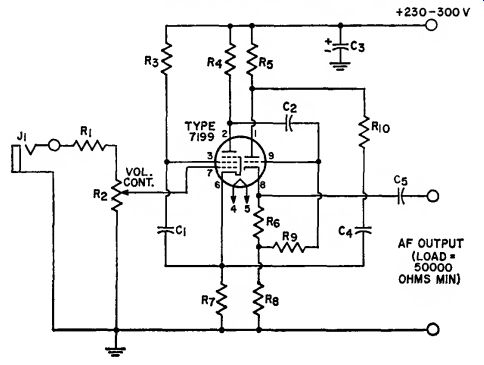
Cathode Follower (Low-Impedance) Output
Parts List
C1=0.1 nF, paper, 400 V
C2=0.01 uF, paper, 400 V
C3=20 uF, electrolytic, 400 V
C4=0.26 uF, paper, 400 V
C5=0.22 uF, paper, 600 V
J1=Input connector, shielded, for high-impedance ceramic phono pickup (0.5-volt output)
Ri=1.8 megohms, 0.5 watt
R2=Volume control, potentiometer, 0.5 megohm, audio taper
Ra=0.82 megohm, 0.5 watt
Ri=0.22 megohm, 0.5 watt
Rs, Rs=4r000 ohms, 0.5 watt
Re=4700 ohms, 0.5 watt
R7=1000 ohms, 0.5 watt
Ro=1 megohm, 0.5 watt
R10=1800 ohms, 0.5 watt
Circuit Description
This two-stage preamplifier is intended for use with a high-impedance ceramic phonograph pickup. The circuit features a cathode-follower (low-impedance) output which makes it possible to install the preamplifier at distances up to 50 feet from the succeeding stage (tone-control or power amplifier). The preamplifier operates from a dc supply of 230 to 300 volts and a heater supply of 6.3 volts. These voltages can usually be obtained from the power supply for the power amplifier in the audio The preamplifier uses a 7199 triode-pentode in a high-gain pentode input stage and a triode cathode follower output stage. These stages provide the amplification necessary to increase th6 output from a crystal phonograph pickup, applied at J1, to the level required to drive an audio power amplifier. The output of the preamplifier, coupled from the cathode of the 7199 triode section, may be applied directly to the power amplifier, or to an intermediate tone control amplifier.
29-19 LOW-DISTORTION PREAMPLIFIER
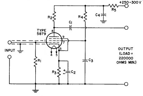
For Low-Output, High-Impedance Microphones
Sensitivity=3 millivolts rms input for output of 220 millivolts.
Parts List
C1=0.047 uF, paper, 400 V
C2=25 nF, electrolytic, 25 V
Cs=0.22 uF, paper, 400 V
C<=40 uF, electrolytic, 450 V
Ri-2.2 megohms, 0.5 watt
Rs=0.1 megohm, 0.5 watt
Rs=1000 ohms, 0.5 watt
Ri=0.47 megohm, 0.5 watt
R-22000 ohms, 0.5 watt
Circuit Description
This single-stage preamplifier is intended for use with a high-fidelity, high-impedance crystal or dynamic microphone. The circuit uses a 5879 low-noise sharp-cutoff pentode in a conventional amplifier circuit that has a high-impedance output, a voltage gain of approximately 70, and a flat frequency response over the audio range. Because of its high out put impedance, the preamplifier should be mounted on the same chassis as the power amplifier and tone-control amplifier (if used).
Heater and dc power for the circuit can be obtained from the power supply for the audio power amplifier.
29-20 BASS AND TREBLE TONE-CONTROL AMPLIFIER
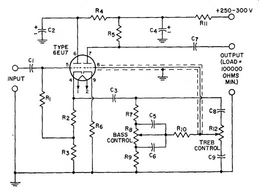
Sensitivity=0.5 volt rms input for output of 1.25 volts with controls set for flat response.
Parts List
C1=0.047 «F, paper, 400 V
Ca, C<=20 uF, electrolytic, 450 V
Ca=0.1 fiF, paper, 400 V
Cs=0.0022 iiT, paper, 400 V
Co=0.022 «F, paper, 400 V
Cj=0.22 juF, paper, 400 V
Cs=220 pF, ceramic or mica, 500 V
Co=0.0022 /»F, paper, 400 V
Ri=0.47 megohm, 0.5 watt
R2=1500 ohms, 0.5 watt
R3, Ru=15000 ohms, 0.5 watt
R1=22000 ohms, 0.5 watt
R.i, R7, Rio=0.1 megohm,
0.5 watt Ro=1000 ohms, 0.5 watt
Rs=Bass control, potentiometer, 1 megohm, audio taper
R»=10000 ohms, 0.5 watt
Ri2=Treble control, potentiometer, 1 megohm, audio taper
Circuit Description
This high-fidelity tone-control amplifier uses a 6EU7 low-noise twin triode in a two-stage amplifier cascade that consists of an input cathode follower connected to a triode voltage amplifier through a frequency-sensitive (tone-control) interstage coupling network. The bass and treble controls in the coupling network can be adjusted to provide up to 16 dB of boost or attenuation (cut) at 30 Hz and at 15 kHz. With the bass and treble controls set at the mid-range positions, the amplifier provides an over-all voltage gain of approximately 2.5, and its frequency response is flat within ±1dB from 30 Hz to 15 kHz.
The tone-control amplifier is designed for use immediately ahead of an audio power amplifier, such as the 15-, 30-, or 50-watt unit (circuit 29 9, 29-10, or 29-11, respectively).
Operating power for the tone-control circuit can usually be obtained from the power supply for the power amplifier. For operating convenience, the volume control on the power amplifier may be physically located on the tone-control chassis. In this case, it is advisable to insert a 1-megohm resistor in place of the volume control on the power amplifier. If partial compensation for the reduced high- and low-frequency sensitivity of the ear at low volume levels is desired, the volume-control potentiometer may be replaced by a loudness-control potentiometer.
29-21 ELECTRONIC VOLT-OHMMETER
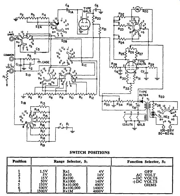
Circuit Description
This electronic volt-ohm meter can be used to measure rms values of ac sine-wave voltages from 0.1 to 1500 volts, dc voltages from 0.2 to 1500 volts, peak-to-peak voltages from 0.2 to 4000 volts, and resistances from 0.2 ohms to 1000 meg ohms. Within these over-all limits, a Range Selector (S1) can be used to select seven different measurement ranges for each measurement function, as shown in the switch-position chart. The mode of operation of the volt-ohm meter is determined by the setting of the five-position (OFF, AC, -DC, +DC, and OHMS) Function Selector (S2). A section (S_2D) of the Function Selector is also used to control the application of the 117 volt, 60-Hz, input ac power. The ac input power is converted to dc power by the 1N1764 selenium rectifier and associated components. A 6.3-volt secondary winding of power trans former T1 supplies power to the tube heaters. A neon lamp connected across the primary of power trans former T1 lights when ac power is applied to the circuit.
A balanced push-pull dc amplifier, which includes a dc microammeter M1 connected as part of a dc bridge network between the two plate sections of the stage, is used as the basic measuring circuit for each measurement function of the volt-ohm meter. This circuit has a linear response, excellent stability, and a very high input impedance.
Calibration adjustments are provided for each mode of operation to as sure that accurate measurements are obtained. If desired, the ZERO ADJ potentiometer Rse may be adjusted to provide a center-scale zero reading on the meter, which is useful in discriminator and bias voltage measurements.
For ac voltage measurements, Function Selector S2 must be rotated to the AC position. The ac voltage to be measured, applied between the AC-OHMS and COMMON terminals, is coupled through contacts 10 and 9 of Sia to the ac-voltmeter multipliers (R» through Rt ). The ac voltage from one of the taps on the multiplier, as determined by the setting of the ...
-----
708 SWITCH POSITIONS
Notes : 1. Switches are shown in their maximum counterclockwise position (S1=1.5 V, R X 1 ; S2="OFF").
2. The accuracy of the volt-ohm meter depends upon the accuracy of the multiplier resistors.
Parts List
Bi= Battery, 1.6 V C1=470 pF, ceramic disc, 1600 V C2=0.001 uF, ceramic disc, 500 V Ca=0.47 uF, tubular, 400 V G<, Cs=0.02 uF, ceramic disc, 400 V Ct, Ct=0.006 uF, ceramic dUc. 200 V Cs=10 uF. electrolytic, 400 V Fi=Fuse, 0.5 ampere Mi=Meter, dc, 0-200 /lA NE2=Neon lamp Ri=DC-voltage probe isolating resistor, 1 meg ohm, 0.25 watt R2=138000 ohms, 0.25 watt Ra=320000 ohms, 0.5 watt R<=0.9 megohm, 1 watt Rs.
Ris=l megohm, 0.25 watt
Rs, Ria, R25, Ri7=10000 ohms, 0.5 watt
R7=20000 ohms, 0.25 watt
Rs=70000 ohms, 0.25 watt
Ro=:0.2 megohm, 0.25 watt
R»=0.7 megohm, 0.25 watt
Ru=2 megohms, 0.25 watt
Ria=7 megohms, 0.25 watt
Ria=8.2 ohms, wire-wound,
0.5 watt Rh=100 ohms, 0.25 watt Ri5=1000 ohms, 0.25 watt Ri7=0.1 megohm, 0.25 watt Ri9=10 megohms, 0.25 watt R2o=20 megohms, 0.25 watt
R2i=91 megohms, 0.5 watt
Rm=10000 ohms, potentiometer ac calibration,
0.5 watt
R23=10000 ohms, potentiometer dc calibration,
0.5 watt
R2t=15000 ohms, potentiometer, ohms adjustment,
0.25 watt Rse=10000 ohms, potentiometer, zero adjustment,
0.25 watt R28=3.3 megohms, 0.5 watt Ri>o=6.8 megohms, 0.5 watt
R30, R3i=330 ohms, 0.5 watt R32=15000 ohms, 0.5 watt Ra3=27000 ohms, 0.5 watt Rm=10000 ohms, potentiometer, ac balance,
0.5 watt R35=47000 ohms, 0.5 watt Rm=0.22 megohm, 0.5 watt Si=Range selector switch, 7 position, RCA stock No.
217924 or equiv.
S2=Function selector switch, 5 position, RCA stock No. 217923 or equiv.
T1=Power transformer, 105-125 volts rms. 50-60 Hz, RCA stock No. 217921 or equiv.
Range Selector (Sia section), is rectified by the 6AL5 twin diode. The resultant dc voltage across the rectifier bleeder resistors R2i and R31 is proportional to the ac voltage from the multiplier network. This voltage is then coupled through contacts 4 and 5 of S2B , through one of the contacts 4 through 10 (as determined by setting of Range Selector) and contact 1 of Sic, and through contacts 1 and 2 of S»a to the pin 2 control grid of the 12AU7A twin triode in the balanced dc amplifier. This input disturbs the balance of the amplifier and a current proportional to the ac input flows through the dc micro ammeter connected between the plates of the 12AU7. The pointer on the microammeter is then deflected to indicate the value of the voltage being measured.
With the Function Selector rotated to either -DC or +DC, a dc voltage being measured is coupled through the 1-megohm probe R1, the DC VOLTS terminal, and contacts 6 and 5 of S2b to the dc-voltmeter multipliers (Ro through R12). The 1-meg ohm resistance of the dc probe together with the resistance of the multipliers results in an input resistance of 11 megohms for dc voltage measurements. The dc voltage from the appropriate tap on the multiplier network selected by the Sic and Sid sections of the Range Selector is coupled through contact 1 of these switch sections (or contact 3 of SIC ) and contacts 1 (or 3) and 2 of S21 to the input of the balanced dc amplifier. The pointer of the microammeter in the balanced amplifier is then deflected to provide an indication of the value of the dc voltage being measured. The S2c section of the Function Selector reverses the connections of the microammeter when the Function Selector is rotated from -DC to +DC so that current will flow through the microammeter in the same direction regardless of whether a negative or positive dc voltage is being measured.
For resistance measurements, the Function Selector is rotated to the OHMS position, and the external resistance to be measured is connected between the AC-OHMS and COMMON terminals of the volt-ohm meter. A 1.5-volt dry cell then causes current to flow through the external resistance, through contacts 10 and 11 of S2a, and through one of the ohmmeter-section multiplier resistors (Rl3 through Rw), as determined by the setting of the Range Selector (Sib section). Because the multiplier resistance is fixed for each range, the voltage developed across the external resistance provides an accurate indication of the value of this resistance.
This voltage is coupled through contacts 10 and 2 of S2i to the input of the balanced dc amplifier. The pointer of the microammeter is then deflected to indicate the value of the resistance being measured.
29-22 SERIES-TYPE STABIL
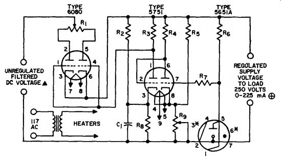
Circuit Description
This series-type stabilized voltage supply uses type 5651A as a voltage reference tube, type 6080 as a series regulator tube, and type 5751 as a control tube. In this circuit, the 5651A supplies a fixed reference voltage between the grid of the first unit of the 5751 and its cathode return. Changes in supply voltage to the load are amplified by the 5751 which is connected as a two-stage dc amplifier to control the drop VOLTAGE SUPPLY through the 6080. The resulting out put voltage is essentially independent of change in load current.
The voltage regulation of this supply operated at a fixed line voltage of 117 volts and an output voltage of 250 volts is less than 0.2 volt over the current range of 0 to 225 milliamperes. At full current, the regulation for a variation of ± 10 percent in line voltage is less than 0.1 volt.
Parts List
R:> = 470000 ohms, y. watt m = 470000 ohms, 1/4 watt Rs = 12000 ohms, 2 watts Ro =: 68000 ohms, 1 watt R7 = 1 megohm, watt Rs = 15000 ohms, 2 watts R» =z Output voltage-control potentiometer, 10000 ohms C1 = 0.1 «F. 400 volts Ri = Plate current balancing potentiometer, 160 ohms, 10 watts Rj = 12000 ohms, 2 watts Notes: * 375 volts approx. at aero load current; 325 volts approx. at 225 milliamperes load current.
Socket connections for the 5651A are made so that removal of the 5651A from its socket opens the load.
* Pins 3 and 6, do not use.
29-23 ALL-PURPOSE DC POWER SUPPLIES
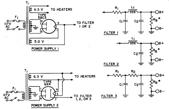
* Bleeder Rb can be omitted if an external load is permanently connected across the output terminals. Bleeder current should be approximately 10 percent of the load current.
Circuit Description
In these power-supply circuits, 5BC3 and 6X4 full-wave rectifier tubes are used to convert ac input power to dc output power in various combinations of output voltage and load current. The 5BC3 tube is a directly heated novar type intended for use in power supplies for radio equipment, television receivers, and other applications that have relatively high dc requirements. The 6X4 tube is an indirectly heated miniature type used primarily in power supplies for automobile and ac-operated radio receivers and other equipment that have moderate dc requirements.
In each rectifier circuit, the 117 volt ac input power is applied to the primary of a step-up power trans former T,. The two plate sections of the rectifier tube are connected to opposite ends of the center-tapped secondary winding of transformer T1. With respect to the grounded center tap, the voltage applied to each plate of the rectifier tube, there fore, is 180 degrees out of phase with that applied to the other plate.
With an external load connected to the rectifier cathode, pulses of current flow alternately to one plate and then to the other plate for each half cycle of the ac input power.
This 120-Hz pulsating current develops a positive dc voltage across the load circuit.
Removal of virtually all the 120-Hz ripple component from the dc output can be accomplished by connection of a suitable filter net work between the rectifier output (cathode) and the load circuit. Either Filter 1 or Filter 2 provides adequate filtering for the 5BC3 circuit.
Any one of the three filter networks is satisfactory for use with the 6X4 circuit. Filter 3 is not recommended for use with the 5BC3 circuit be cause the use of the two resistors R1 and R2 in series with the relatively high output results in excessive power loss.
The chart shown with the rectifier circuits lists a wide range of dc output voltage obtainable for various values of load current. Proper selection of power transformer T1, of the type of filter network, and of the values of filter choke L1 and resistors R1 and R» results in the desired combination of output voltage and current.
BLACK-AND-WHITE TELEVISION RECEIVER
Circuits 29-24 through 29-28 are essentially identical to the corresponding circuits in the RCA-KCS 152 Television Receiver. These circuits comprise a complete intercarrier television receiver with the exception of the deflection coils and the picture tube. Portions of any television receiver, however, are required to operate over an extremely wide range of very high frequencies.
The construction of such circuits requires more than ordinary skill and experience and the use of sophisticated test equipment (see general consideration for the construction of high-frequency and broad band circuits at the beginning of this section). Home construction of such circuits is not recommended un less the builder has had consider able experience in this type of work.
The chassis of circuits 29-24 through 29-28 are connected to one side of the ac line during operation.
Servicing of these circuits should not be attempted by persons not familiar with the following precautions necessary when working on this type of equipment:
1. An isolation transformer should be inserted between the receiver and the ac line before any servicing is at tempted.
2. If the receiver must be operated directly from the ac supply, the power plug should be inserted in the proper direction to connect the chassis to the ground side of the ac line. An ac voltmeter should be used to measure the voltage between the chassis and the power-source ground; no voltage reading should be obtained. If a reading is obtained, the power plug should be reversed and another check made for a zero reading.
Cont. to part 2b.