THE tube data given in the following Technical Data section include ratings, typical operation values, characteristics, and characteristic curves.
The values for grid-bias voltages, other electrode voltages, and electrode supply voltages are given with reference to a specified datum point as follows: For types having filaments heated with dc, the negative filament terminal is taken as the datum point to which other electrode voltages are referred.
For types having filaments heated with ac, the mid-point (i.e., the center tap on the filament-transformer secondary, or the mid-point on a resistor shunting the filament) is taken as the datum point. For types having uni-potential cathodes indirectly heated, the cathode is taken as the datum point.
Ratings are established on electron tube types to help equipment designers utilize the performance and service capabilities of each tube type to best advantage. Ratings are given for those characteristics which careful study and experience indicate must be kept within certain limits to insure satisfactory performance.
Three rating systems are in use by the electron-tube industry. The oldest is known as the Absolute Maximum system, the next as the Design Center system, and the latest and newest as the Design Maximum system. Definitions of these systems have been formulated by the Joint Electron Device Engineering Council (JEDEC) and standardized by the National Electrical Manufacturers Association (NEMA) and the Electronic Industries Association (EIA) as follows:
Absolute Maximum ratings are limiting values which should not be exceeded with any tube of the specified type under any condition of operation.
These ratings are not used too often for receiving types, but are generally used for transmitting and industrial types.
Design Center ratings are limiting values which should not be exceeded with a tube of the specified type having characteristics equal to the published values under normal operating conditions. These ratings, which include allowances for normal variations in both tube characteristics and operating conditions, were used for most receiving tubes prior to 1957.
Design Maximum ratings are limiting values which should not be exceeded with a tube of the specified type having characteristics equal to the published values under any conditions of operation. These ratings include allowances for normal variations in tube characteristics, but do not provide for variations in operating conditions. Design Maximum ratings were adopted for receiving tubes in 1957.
Electrode voltage and current ratings are in general self-explanatory, but a brief explanation of other ratings will aid in the understanding and interpretation of tube data.
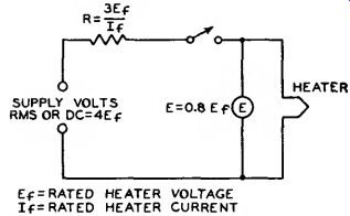
Heater warm-up time is defined as the time required for the voltage across the heater to reach 80 percent of the rated value in the circuit shown in Fig. 124. The heater is placed in series with a resistance having a value 3 times the nominal heater operating resistance (R = 3 Er/Ir), and a voltage having a value 4 times the rated heater voltage (V = 4 E() is then applied. The warm up time is determined when:
E = 0.8 E».

Fig. 124--Test circuit for measuring healer warm-up time.
Plate dissipation is the power dissipated in the form of heat by the plate as a result of electron bombardment It is the difference between the power supplied to the plate of the tube and the power delivered by the tube to the load.
Peak heater-cathode voltage is the highest instantaneous value of voltage that a tube can safely stand between its heater and cathode. This rating is applied to tubes having a separate cathode terminal and used in applications where excessive voltage may be introduced between heater and cathode.
Maximum dc output current is the highest average plate current which can be handled continuously by a rectifier tube. Its value for any rectifier tube type is based on the permissible plate dissipation of that type. Under operating conditions involving a rapidly repeating duty cycle (steady load), the average plate current may be measured with a dc meter.
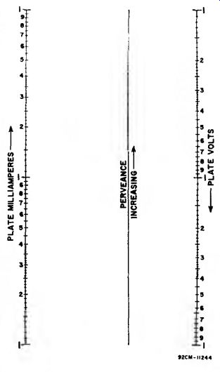
The nomograph shown in Fig. 125 can be used to determine tube voltage drop or plate current for any diode unit when values for a single plate voltage, plate-current condition are available from the data. It can also be used to compare the relative perveance (G = Ib/Eb 8/2) of several diodes. Perveance can be considered a figure of merit for diodes; high-perveance units have lower voltage drop at a fixed current level.

Fig. 125--Diode perveance nomograph.
Tube voltage drop or plate current for a specific diode unit can be determined as follows: First, convenient values are selected for the plate-voltage and plate-current scales of the nomograph. The published plate-current and plate-voltage values are then located on the scales and connected with a straight edge. The intersection of the connecting line with the perveance scale is then used as a pivot point to determine the value of tube voltage drop corresponding to a desired current value, or the value of plate current corresponding to a desired tube voltage drop. Because the pivot point for a specific diode unit represents its perveance, the pivot points for several units (plotted to the same scales) can be used to compare their relative perveance.
For example, type 5U4GB has a tube voltage drop (per plate) of 44 volts at a plate current of 225 milliamperes.
Convenient scales for this type are from 1 to 100 volts for plate voltage and from 10 to 1000 milliamperes for plate current. The points 44 volts and 225 milliamperes are then connected with a straight line to determine the pivot point. Using this pivot point, it is easy to determine such values as a plate current of 150 milliamperes at a tube voltage drop of 33 volts, or a voltage drop of 25 for a current of 100 milliamperes.
For readings in the order of one volt and /or one milliampere, the nomograph is not accurate because of the effects of contact potential and initial electron velocity.
Maximum peak plate current is the highest instantaneous plate current that a tube can safely carry recurrently in the direction of normal current flow.
The safe value of this peak current in hot-cathode types of rectifier tubes is a function of the electron emission avail able and the duration of the pulsating current flow from the rectifier tube in each half-cycle.
The value of peak plate current in a given rectifier circuit is largely determined by filter constants. If a large choke is used at the filter input, the peak plate current is not much greater than the load current; but if a large capacitor is used as the filter input, the peak current may be many times the load current. In order to determine accurately the peak plate current in any rectifier circuit, measure it with a peak indicating meter or use an oscillograph.
Maximum peak inverse plate voltage is the highest instantaneous plate voltage which the tube can withstand recurrently in the direction opposite to that in which it is designed to pass current. For mercury-vapor tubes and gas filled tubes, it is the safe top value to prevent arc-back in the tube operating within the specified temperature range.
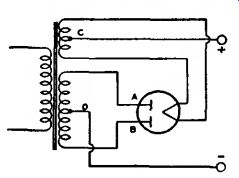
Referring to Fig. 126, when plate A of a full-wave rectifier tube is positive, current flows from A to C, but not from B to C. because B is negative. At the instant plate A is positive, the filament is positive (at high voltage) with respect to plate B. The voltage between the positive filament and the negative plate B is in inverse relation to that causing current flow. The peak value of this voltage is limited by the resistance and nature of the path between plate B and filament. The maximum value of this voltage at which there is no danger of breakdown of the tube is known as maximum peak inverse voltage.

Fig. 126-Schematic diagram of full-wave rectifier tube and circuit connections.
The relations between peak inverse voltage, rms value of ac input voltage, and dc output voltage depend largely on the individual characteristics of the rectifier circuit and the power supply.
The presence of line surges or any other transient, or wave-form distortion, may raise the actual peak voltage to a value higher than that calculated for sine-wave voltages. Therefore, the actual inverse voltage, and not the calculated value, should be such as not to exceed the rated maximum peak inverse voltage for the rectifier tube. A calibrated cathode-ray oscillograph or a peak indicating electronic voltmeter is useful in determining the actual peak inverse voltage.
In single-phase, full-wave circuits with sine-wave input and with no capacitor across the output, the peak in verse voltage on a rectifier tube is approximately 1.4 times the rms value of the plate voltage applied to the tube.
In single-phase, half-wave circuits with sine-wave input and with capacitor in put to the filter, the peak inverse voltage may be as high as 2.8 times the rms value of the applied plate voltage.
In polyphase circuits, mathematical determination of peak inverse voltage requires the use of vectors.
The Rating Chart for full-wave rectifiers presents graphically the relationships between maximum ac voltage input and maximum dc output current derived from the fundamental ratings for conditions of capacitor-input and choke-input filters. This graphical presentation provides for considerable latitude in choice of operating conditions.
The Operation Characteristics for a full-wave rectifier with capacitor-input filter show by means of boundary line the limiting current and voltage relationships presented in the Rating Chart.
The Operation Characteristics for a full-wave rectifier with choke-input filter not only show by means of boundary line the limiting current and voltage relationships presented in the Rating Chart, but also give some information as to the effect on regulation of various sizes of chokes. The solid-line curves show the dc voltage outputs which would be obtained if the filter chokes had infinite inductance. The long-dash lines radiating from the zero position are boundary lines for various sizes of chokes as indicated. The intersection of one of these lines with a solid-line curve indicates the point on the curve at which the choke no longer behaves as though it had infinite inductance.
To the left of the choke boundary line, the regulation curves depart from the solid-line curves as shown by the representative short-dash regulation curves.
Typical Operation Values. Values for typical operation are given for many types in the Technical Data section.
These typical operating values are given to serve as guiding information for the use of each type. These values should not be confused with ratings, because a tube can be used under any suitable conditions within its maximum ratings, according to the application.
The power output value for any operating condition is an approximate tube output-that is, plate input minus plate loss. Circuit losses must be subtracted from tube output in order to determine the useful output.
Characteristics are covered in the Electron Tube Characteristics section and such data should be interpreted in accordance with the definitions given in that section. Characteristic curves represent the characteristics of an aver age tube. Individual tubes, like any manufactured product, may have characteristics that range above or below the values given in the characteristic curves.
Although some curves are extended well beyond the maximum ratings of the tube, this extension has been made only for convenience in calculations. Do NOT operate a tube outside of its maximum ratings.
Interelectrode capacitances are direct capacitances measured between specified elements or groups of elements in electron tubes. Unless otherwise indicated in the data, all capacitances are measured with filament or heater cold, with no direct voltages present, and with no external shields. All electrodes other than those between which capacitance is being measured are grounded. In twin or multi-unit types, inactive units are also grounded.
The capacitance between the input electrode and all other electrodes, except the output electrode, connected together is commonly known as the input capacitance. The capacitance between the output electrode and all other electrodes, except the input electrode, connected together is known as the output capacitance.
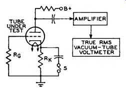
Hum and noise characteristics of high-fidelity audio amplifier tube types such as the 7025 and the 7199 are tested in an amplifier circuit such as that shown in Fig. 127. The output of the test circuit is fed into a low-noise amplifier. The bandwidth of this amplifier depends on the characteristic being measured. If hum alone is being tested, a relatively narrow bandwidth is used to include both the line frequency and the major harmonics generated by the tube under test. In noise or combination hum-and-noise measurements, the bandwidth is defined in the registration of the tube type.

Fig. 127--Test circuit for measuring hum and noise characteristics of
high-fidelity audio-amplifier tubes.
The amplifier gain is calibrated so that the vacuum-tube voltmeter measures hum and noise in microvolts referenced to the grid of the tube under test.
A pentode can also be evaluated in this manner by the addition of a screen grid supply adequately bypassed at the tube screen-grid pin connection. Power supply ripple at the plate of the tube under test must be negligible compared to its hum and noise output. Extraordinary shielding of both the test socket and the associated operating circuit is required to minimize capacitances between heater leads and high-impedance connections.
The test-circuit components are determined by the tube type being tested and the type of hum to be Controlled.
Heater-cathode hum can be eliminated from the measurement by closing the switch S. The circuit can also be made more or less sensitive to heater-grid hum by increasing or decreasing the grid resistance Rs. No circuit changes affect the component of magnetic hum generated by the tube.
Grid-No. 2 (Screen-grid)
Input is the power applied to the grid-No. 2 electrode and consists essentially of the power dissipated in the form of heat by grid No. 2 as a result of electron bombardment. With tetrodes and pent odes, the power dissipated in the screen grid circuit is added to the power in the plate circuit to obtain the total B-supply input power.
When the screen-grid voltage is supplied through a series voltage-drop ping resistor, the maximum screen-grid voltage rating may be exceeded, provided the maximum screen-grid dissipation rating is not exceeded at any signal condition, and the maximum screen-grid voltage rating is not exceeded at the maximum-signal condition. Provided these conditions are fulfilled, the screen-grid supply voltage may be as high as, but not above, the maximum plate voltage rating. The rating chart on page 300 shows the relationship between the maximum permissible input power to the screen grid and the screen-grid supply voltage.