11-1. Limitations
The average service technician, experimenter, or radio amateur should not attempt to set himself up as a repair expert for his signal generators, no matter how well he may know their operation. Any serious deviation of performance from that specified by the manufacturer should be referred to the manufacturer himself, since he is the final authority on the equipment of his design.
However, the ordinary line of depreciation troubles due to dust, aging, corrosion, temperature, and vibration can be either avoided or remedied by the technician himself by proper routine maintenance. It will be a great saving in time and money, as well as a personal satisfaction to know that his equipment is checked and ready to go at all times.
11-2. Erratic Operation and Instability
These troubles are frequently encountered in signal generators which have undergone rugged treatment for some time. They are usually due to defective tubes, dirty or corroded capacitor rotors, loose bearings, worn bushings, or too much play in the rotor shafts of tuning capacitors. If the dial readings are all in error by the same linear distance along the dial circumference (of circular dials which rotate) the dial may have been tightened on the shaft before the frequency calibration was completely checked, or the dial may have slipped on the shaft. If the dial calibration is stationary, and a pointer moves over it, the same trouble may be due to a similar displacement of the pointer on its shaft.
Sometimes frequency readings become variable and cannot be depended upon. This condition may be the result of dial slippage due to loose set screws, defective trimmer capacitor plates, backlash in the tuning capacitor, or intermittent tube defects. Sometimes a loose connection in the tuned circuit between capacitor and coil, or loose ground connection can cause the same trouble.
If the dial readings tend to develop error only at certain spots, look for a poor connection (such as might be caused by a cold-soldered joint), a partial short circuit in the oscillator coil, or defective bypass or trimmer capacitors.
The shafts and couplings of generators should be checked for any binding, and wear in gears and other drives repaired. Carbon tetra chloride makes a good cleaning agent for shaft bearings, but must not be used near certain plastic materials which may dissolve in it.
It is a good idea, during periodic inspections, to blow between the plates of variable capacitors with a low pressure air hose or to slide a pipe cleaner soaked with carbon tetrachloride between them. A small amount of lubricant, such as clock oil, should be applied as a slush to the surfaces of the variable capacitors, and a very small amount to the bearings. In all cases, lubricant should be applied very sparingly, with the main objective to keep all parts clean. Variable capacitor wipers may be removed, cleaned and the metal bent very slightly to provide greater contact pressure.
11-3. Calibration of Signal Generators
After a signal generator has been in use for some time, the calibration may develop some error due to aging, dust, moisture, and other causes. If certain components are replaced, recalibration may be necessary. For these reasons, the service technician or experimenter should be prepared not only to check the calibration of his generator, but also to make small adjustments to correct it. Naturally, very radical failure of calibration should be referred to the generator manufacturer.
A very convenient and accurate source of frequency standards for checking calibration of signal generators is the a-m broadcast band. A-m broadcast stations are required by law to keep their carrier frequencies within 20 hz of specified frequency, and most of them can be depended upon to remain within 10 hz. This means that all frequencies of the generator below the low edge of the a-m broadcast band (550 khz) as well as those within the broadcast band itself, can be checked against the· signals of the a-m broadcast stations whose frequencies are appropriate. Since there is a broadcast channel every 10 khz between 550 khz and 1600 khz, there are bound to be a large number of stations receivable in any one area which can be employed for frequency calibration checking.
For checking, the signal generator is coupled to the receiver enough to provide a reasonably strong signal of about the same strength as the broadcast station signals to be checked against. The antenna is left on the a-m broadcast receiver, so that broadcast station signals are received with normal strength. The set-up is shown in Fig. 11-1.
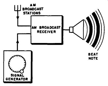
Fig. 11-1. Set-up for checking frequency calibration of signal generator in
and below the a-m broadcast band.
The signal generator is tuned until either its fundamental signal, or a harmonic, is zero-beat with a selected broadcast station signal. The frequency of the generator signal must then be either exactly equal to that of the broadcast station, or exactly equal to a sub-multiple of the broadcast station frequency (one-half, one-third, one-quarter, etc.). One broadcast station can be used to check a number of signal generator dial points. For example, suppose the broadcast receiver is tuned to a station on 600 khz. Then, when the signal generator is adjusted to 100 khz, the sixth harmonic beats against the broadcast station signal; when adjusted to 120 khz, the fifth harmonic; 150 khz, the fourth harmonic; 200 khz, the third harmonic; 300 khz, the second harmonic; and 600 khz, the fundamental. All these frequencies can be checked for the generator with the receiver tuned to only one station.
One precaution must be observed; when there is modulation on the broadcast station, a false beat may be obtained by beating against the sidebands of the station, rather than the carrier. This is not a serious problem when sub-multiples are used as already described here, but does become important when a harmonic of the checking frequency is used, rather than a sub-multiple.
It may be necessary to connect a variable capacitor in series with the antenna lead if the a-m broadcast station used is too strong, but ordinarily the signal generator attenuators will provide sufficient variation of relative strength to provide the most useful beat signal.
Of particular interest to the radio service technician are the standard intermediate frequencies, 455 khz in particular. If there is a receivable broadcast station on 910 khz, this station carrier makes an excellent check point, since the second harmonic of the signal generator signal can be beat against it. If the broadcast station on 910 khz is strong enough, a quick setting of the signal generator can be made against this carrier each time a receiver is checked or aligned, thus ensuring a more exact intermediate-frequency signal than could be obtained from setting with the generator dial alone.
When generator frequencies above the a-m broadcast band are to be checked, the a-m broadcast stations cannot be used in just this way.
However, what can be done is to use an additional generator or frequency meter (any good stable oscillator will do) which is tuned to an appropriate broadcast station carrier. Harmonics of this generator or oscillator can then be mixed in another receiver with the signal from the generator to be cheeked. Figure 11-2 shows an example. The calibration of signal generator A is to be checked at 10 mhz, so its dial is set for approximately that frequency, and its output is coupled to receiver X. The other oscillator or signal generator B is coupled both to receiver X and to another receiver, receiver Y. Signal generator B is tuned to some sub-multiple of the IO-mhz calibration frequency, in the example we have chosen 1 mhz (1,000 khz). A 1,000 -khz broadcast station is received on receiver Y, along with the 1,000 -khz signal from signal generator B.
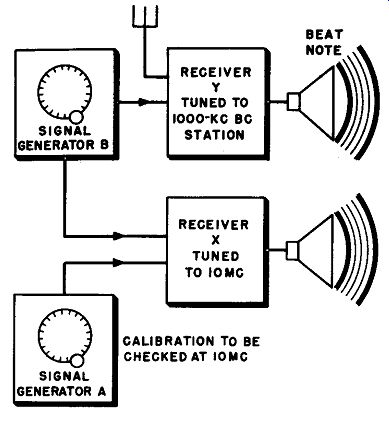
Fig. 11-2. Method for checking calibration of signal generator at frequencies
above the a-m broadcast band.
Signal generator B is adjusted until its signal is zero-beat with the broad cast station signal. The tenth harmonic of the signal from signal generator B is then received on receiver X, which is tuned to 10 mhz, along with the 10 mhz signal from generator A. Signal generator A is then adjusted to zero-beat with the 10th harmonic from signal generator B, and is then exactly at 10 mhz. The dial calibration reading can then be observed on signal generator A, and the amount of error determined.
If a frequency standard operating on 100 khz or 1,000 khz or other even low-frequency value is available, its regularly repeating harmonics can be used as check points right up through the short-wave range, provided a reasonably sensitive receiver is used with the standard and generator outputs fed into its antenna circuit. The process is then similar to that outlined in Section 10-9.
11-4. Compensating or Adjusting for Calibration Errors
By the methods discussed in the previous section we can determine whether or not there is dial calibration error, and about how great the error is. Now the question is "what to do about it?" There are two possible courses of action.
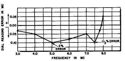
Fig. 11-3. Calibration correction curve and data taken to derive it, for one
range of a signal generator.
First, we can develop a correction curve or table which will tell us just how much off the dial reading is at any particular frequency. It is seldom that the error will change very rapidly, so corrections will remain constant in most cases for up to one half of a dial coverage or more. In fact, if the frequency scale is linear, one correction may take care of a complete band coverage.
Typical dial error data taken for an actual signal generator are shown in Fig. 11-3, with a correction curve plotted from them. Note that there is a rapid change in dial in dial accuracy at the high frequency end of the range. This is a common effect, and makes clear that it is not desirable to operate with this signal generator set at the high end of any of its ranges. This is where the tuning capacitor is at its minimum value, and errors can easily be present. Good signal generators allow a generous overlap between ranges, so there is no need to operate too closely to the high edge of any of them. Note that readings were taken much closer together when changes in the error started to take place more rapidly; this should always be done.
The second method for overcoming calibration error is by adjustment of any trimmer capacitors provided by the manufacturer for this purpose. The manufacturer's instruction manual should be consulted and only adjustments recommended by him made. Trimmer adjustment may not always provide a perfect calibration, since there is a certain allowable error due to production tolerances. For this reason, it is always desirable to make some kind of independent frequency check whenever a job which requires frequency accuracy is started.
11-5. Checking Attenuator Accuracy and Voltage Output
Step attenuators can be checked for accuracy by the set-up shown in Fig. 11-4. The modulation is turned on in the signal generator with the generator set for a convenient frequency, the generator signal is rectified by the detector and the modulation signal amplified by the vertical amplifier of the oscilloscope. With the horizontal sweep adjusted for some high value, the result will be a solid pattern whose height is proportional to the output r-f voltage of the generator. The pattern is adjusted for a size which takes up most of the screen; and then its height is measured. If the oscilloscope has a cross-hatched screen, the height can be observed in terms of squares on the screen. Now the step attenuator is reduced to the next lower position, nominally one-tenth output. The voltage should drop to one-tenth of its previous value, so the height of the oscilloscope pattern height should drop to one-tenth of its previous value. When the test on one step has been completed, the vertical amplifier of the oscilloscope and the continuous attenuator of the generator are readjusted for full height of the pattern again, and the procedure repeated for the next downward step of the step attenuator.
Microvolt readings are difficult to measure with ordinary equipment except on the higher output settings. There are vacuum-tube voltmeters...
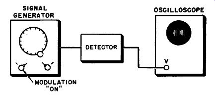
Fig. 11-4. Set-up described in the text for determining action of the step
attenuator.
... available with high frequency probes which will measure down to about 50,000 microvolts (0.05 v). If a field-strength meter is available, it can be used to check output voltage. The output voltage can be quite accurately checked against another generator whose output voltage indications are known to be correct. The two generators are arranged so that each can be connected in exactly the same way to a receiver. The receiver is equipped with an output meter or vacuum-tube voltmeter on the ave lead, if the receiver does not already have an S-meter. The generator known to be accurate is set successively for various values of output voltage. For each value, the generator to be checked is substituted and set for the same output indication on the receiver, at which time the output voltage indication should be the same as for the standard generator.
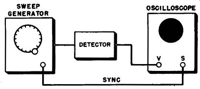
Fig. 11-5. Arrangement of equipment used to check sweep generator response.
11-6. Checking Sweep Generator Amplitude
It is of interest to know the constancy of output voltage of the r-f carrier of a sweep generator over the sweep range. This is important because in sweep response analysis, the response curve exhibited on the oscilloscope screen cannot be accurate if the voltage applied to the receiver input is not constant over the sweep range.
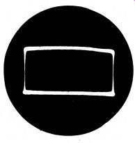
Fig. 11-6. Typical sweep generator response as observed with the set-up of
Fig. 11-5.
A typical set-up for checking sweep amplitude is shown in Fig. 11-5.
The r-f output of the sweep generator is applied to a detector whose response is known to be uniform over the range to be checked. The output of the detector is applied to the vertical circuit of the oscilloscope.
The horizontal deflection of the oscilloscope is controlled by the sync voltage from the sweep generator as in sweep analysis applications.
Figure 11-6 shows the type of generator response which should be obtained. Blanking should be used, since otherwise the response line will be "floating" and there will be no base line to compare it with.
If the response is not flat as is shown, it may be possible to improve it by the use of isolating pads or an impedance matching network at the output end of the cable. If this cannot be done, then at least the technician should be aware of the irregularity of the output voltage so that the response curves traced on the screen with such a generator may be corrected for.
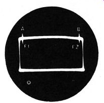
Fig. 11-7. Response of a sweep generator, with marker pips used to determine
sweep width.
11-7. Checking Sweep Width
The sweep width of a generator can be checked with exactly the same set-up as described above for output, except that a marker generator is added. The marker generator is set so the marker pip is at the left end of the response line (a in Fig. 11-7) and the marker frequency is noted. Then the marker generator is readjusted to move the marker pip over to the right end (b in Fig. 11-7). If the first frequency is f_1 and the second is f_2, then the sweep width is equal to f2 minus f1.