AMAZON multi-meters discounts AMAZON oscilloscope discounts
1. The Meaning of Ionization
Atoms and molecules, the normal building blocks of matter, are electrically balanced systems in which the total positive charge is equal to the total negative charge, leaving a net charge of zero. In the fundamental picture of the atom, the positive charge is borne by the nucleus in which reside protons and neutrons while the total excess negative content resides in the orbiting electrons.
Molecules in the atmosphere are constantly subjected to bombardment and collision. These involve both high- and low-speed particles such as alpha particles emitted from radioactive materials in the earth's crust, and secondary cosmic ray particles from the upper atmosphere. The nucleus of the oxygen or nitrogen atom of the air of which these molecules are composed is seldom disturbed by chance collisions with moving particles because it makes a relatively small target. On the other hand, the orbiting electrons are very likely to become involved in direct collisions which lead to their dislocation from the atom to which they belong.
When a neutral atom gains or loses one or more electrons it becomes an ion. The loss of electrons results in a net positive charge on the dismembered particle which is then termed a positive ion.
Much less frequently, an atom may gain one or more electrons to form a negative ion. The term ion is thus much less definitive than other common particle names - electron, proton, etc. -- because it does not state the polarity of the charge, the mass of the particle, or the magnitude of charge it carries. Because of the predominance of positive ions in electrical phenomena, the term ion as used in this guide will refer to positive ions whether or not they are qualified by the adjective "positive;" reference will be made to negative ions by consistently prefixing the adjective "negative." Chance encounters between positive and negative ions in the atmosphere result in gradual re-combinations to form neutral atoms.
But there are always several hundred charged particles per cubic centimeter of ordinary air.
2. Movement of Ionic Particles
Since an ion is a charged particle, a force is exerted upon it when it is placed in an electrostatic field or a magnetic field. The commonest method whereby an electrostatic field may be made to act upon an ion is that in which two electrodes connected to a source of electrical potential are made to establish a potential gradient, G (Fig. 1) . Positive ions in such a gradient are accelerated toward the cathode or negative electrode while negative ions move in the direction of the anode.
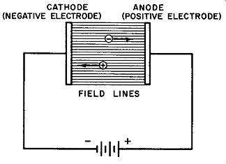
Fig. 1. Field lines and potential gradient between two parallel charged electrodes.
The force exerted on an ion in such a field depends upon the charge on the particle e (coulombs) and the potential gradient E1 (volts per cm) . Expressed in dynes, the force equation is:
F = Ge X 10^7 (1)
The kinetic energy acquired by a charged particle as it traverses the voltage gradient is determined by the magnitude of the charge e in coulombs and the difference of potential V in volts between the two electrodes. In this case, the energy is given in coulomb-volts or joules. That is, W = Ve (2)
... in which W is energy in joules, V is potential difference in volts, and e is charge in coulombs.
The kinetic energy of any moving particle may be expressed in terms of its mass m (gms) and velocity v (cm/sec) thus: W = ½ mv^2 in which W is in ergs, m in gms, and v is velocity in cm/sec.
Since a joule = 10^7 ergs, Equation 3 expressed in joules is W (joules) = ½ mv^2 X 10^-7
From Equations 2 and 4, we derive: Ve = ½ mv^2 X 10^-7
Solving for v, the velocity of the particle:
v (cm/sec) = 4.47 ~ X 10^3 (3)
(4)
(5)
(6)
Problem 1. Find the velocity acquired by an electron in falling through a difference of potential of 10 volts. The approximate charge and mass of an electron are roughly 1.6 X 10^-19 coulombs and 9.1 x 10^-28 gms, respectively.
Solution. Substituting in Equation 6:
v (cm/sec) = 4.47
= 4.47 10 X 1.6 X 10^-19 3 9.1 X 10^-28 X 10 V 10 X 1.76 x 10^8 x 10^3
= 4.47 X 4.20 X 10^7
= 18.8 x 10^7 cm/sec
Since 1 km = 10^5 cm = 0.621 mile km mile V = 1880-- = 1170 - Sec sec
Problem 2. Find the velocity acquired by a mercury ion in falling through the same difference of potential, if the ion bears a positive charge equal numerically to one electron (singly ionized) . The mass of a mercury ion of this kind is roughly 4 X 10^5 times as great as that of an electron.
Solution: Since velocity varies inversely as the square root of the mass, then the velocity of the mercury ion will be roughly .0016 x the velocity of the electron, or approximately 1.9 miles per second.
Often it is of greater importance to know the momentum of a moving ion rather than its velocity. (For all particles in motion at a speed substantially less than that of light, the classical mechanical concept of conservation of momentum may be applied.) This means that the thoroughly practical objective of mathematically determining the force necessary to deflect a moving ion from its path is easily realizable. This problem arises in television, X-ray work, mass-spectrograph analysis, and many other research problems.
Momentum 1s defined as the product of mass and velocity.
That is: Momentum = mv (7) in which m is mass in gms, v is velocity in cm/sec, and momentum is expressed in gm-cm/sec.
As momentum is directly proportional to mass, the mercury ion of Problem 2 has a much greater momentum than the electron even though its velocity is considerably less. This follows from the consideration that a particle in an accelerating field acquires a velocity that is inversely proportional to the square root of the mass while the momentum is proportional to the mass itself. Hence, the product mv in a given field must be greater for particles of greater mass.
This principle is fundamental in the operation of the mass spectrograph and the television picture tube. In the former case, mixed particles are separated by a magnetic field which deflects less massive particles to a greater degree than the more massive ones.
In a picture tube, negative ions that might damage the phosphor of the screen are prevented from reaching it by deflecting the electrons toward the screen through the action of a magnetic field while the heavy negative ions are unaffected and continue on a path which carries them away from the screen.
3. Principles of Gas Conduction
A pair of electrodes immersed in a gas give rise to conduction phenomena very different from those obtained under similar circumstances with charged electrodes in a vacuum. If a voltage is applied to gas-immersed electrodes separated by a small distance (e.g., distances of 1 or 2 cm), a current begins to flow immediately.
Thermionic emission plays no part here since neither of the electrodes is heated enough to produce this effect. This small initial current is due to the ionization of the gas by external influences such as cosmic rays and light photons. Normally, the ions thus formed reach a definite concentration and then begin to recombine to form neutral atoms. The rate of recombination forms an equilibrium state with the rate of formation so that the average number of ions free to act as charge carriers remains fairly constant for a given set of conditions. The process of recombination is a random one; it occurs most readily when ions and electrons chance to drift near each other at low speeds.
As the voltage gradient between the electrodes is increased, the ions move more and more swiftly toward the oppositely charged electrode (Equation 6) and the opportunities for recombination diminish. This leads to an increasing gas current until the point is reached where all the ions produced by external particles and radiation are carried to the oppositely charged electrode, all of them thus contributing to the gas current. Further increases in the potential gradient from this point does not result in a further growth of gas current. The magnitude of the current under these conditions, however, is too small to be of practical value. Should the external ionizing source be removed by shielding or other methods, the conduction current ceases immediately. In Fig. 2, the range from O to A shows the variation of gas current with voltage up to saturation; from A to B, saturation current flows.
4. Non-Self-Maintaining Discharge
As the electrode potential is further increased beyond E1, the current again begins to rise. Restricting our thinking to the electrons that are liberated from the atoms acted upon by the external ionizing agents, we can analyze the action which then takes place qualitatively.
If the voltage between electrodes is high enough, a liberated electron may gather sufficient kinetic energy as it falls through the established potential to free a second electron from the first atom it collides with. Now two electrons are available for further ionization by collision. Since the process is cumulative, it is evident that the possibilities are good for very large currents to flow in the gas. Although the current may rise to 20 times its original value (Point C in Fig. 2), it is still dependent upon the original supply of electrons from the original ionizing source. If this source is removed, the current again falls to zero in an extremely short time. For this reason, such a discharge is known as a non-self-maintaining type.
----The maximum current obtained in this way is called the saturation current and is expressed in amperes per square meter of cross-sectional tube area. It is in the order of 10^-22 amp/m^2.
One of the best examples of an application of a non-self-maintaining discharge is the gas-filled photocell. The process is started by light photons which fall upon a surface having photoemissive characteristics, i.e., a material which emits electrons when struck by light. This surface serves as the cathode of the tube and is made negative with respect to another electrode in the same envelope. As the photoelectrons are drawn toward the anode they develop sufficient kinetic energy to ionize gas molecules in their path. The electrons liberated by ionization contribute to the total gas current by serving as charge carriers so that the intensity of the current rises to a figure from 10 to 20 times as great as it would be in a vacuum.
As the brightness of the light is increased, the increment in current is far greater than it would be, had the whole process taken place in a non-ionizing atmosphere or in a vacuum. Herein lies the unique value of the gas photocell: the presence of gas gives rise to intensified current changes which then result in gas amplification.
Thus, gas phototubes are more sensitive to light variations than their vacuum prototypes.
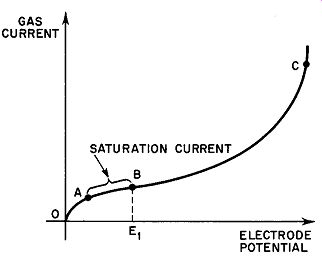
Fig. 2. Variation of gas current with voltage.
The large number of electrons liberated from ionized atoms by the single original electron from the cathode is known as an "electron avalanche." If a symbolizes the number of new electrons (or ions) formed by one electron traveling a distance of l meter through a gas, and d denotes the actual distance between the cathode and the anode of any type of gas-discharge tube, then the number of electrons comprising an electron avalanche started by a single primary electron is shown thus: Number of electrons in avalanche = Ead (8)
...where E is the base of the Naperian system of logarithms.
The term a in this equation is often called the first Townsend coefficient, after the investigator who first proposed a tenable theory explaining "glow discharges." Equation 8 may be amplified by using the expression to show the number of electrons that reach the anode compared to the original number that left the cathode. Thus: (9)
…in which n_a is the number of electrons reaching the anode, nc is the number of electrons leaving the cathode, and E^ad is the avalanche number. If both sides of Equation 9 are multiplied by the electronic charge, the resulting expression is that of the currents in the gas: (10)
in which Ia is the current at the anode and I_o is the current at the cathode. Since I_o in the type of tube we have been discussing is produced entirely by external excitation (light in the phototube), when I0 drops to zero as the excitation is removed, I_a also becomes zero. This explains the non-self-maintaining nature of the discharge.
5. Self-Maintaining Glow Discharge
Should the voltage between the electrodes in the gas discharge tube now be further increased, the current-rise curve becomes steeper and steeper until the gas in the tube breaks down and starts to glow. The glow is usually accompanied by a heavy current, limited principally by the external series resistance. If this resistance is small or not present at all, the current may be destructively great. Removal of the original ionizing source will have no effect in this case. The discharge continues in a self-sustained state, although outside agencies may have played a part in its initiation.
To explain the occurrence of gas breakdown we must search further for some other mechanism of electron production in the system. We find this in the emission of secondary electrons from the cathode due to positive ion bombardment of this electrode. Calling the secondary emission current I., the electron current due to external excitation le, and the total electron current at the cathode I_o , then:
(11)
The total electron current at the cathode is I_o. This means that the ionic current reaching the cathode must be the difference between the anode current Ia and the electron current at the cathode I_o. That is:
Ion current = I_a – I_o (12)
On the basis of statistical averages, a single ion in a gas tube will dislodge n number of electrons from the cathode. Using this symbol, Equation 12 may be re-written: (13)
...where 18 is the secondary emission current. By combining Equations II, 10 and 13, the following expression for Ia is obtained: le Ead Ia= ---,------e-- 1 + n - nEad (14)
From a mathematical point of view, the anode current Ia tends to increase without limit when the denominator of the fraction in Equation 14 approaches zero. This can occur when: nEad = 1 + n (15)
Since an infinite current is impossible, the equations imply that there will be a very great increase of current as nEad approaches 1 + n. Thus, the transition from the non-self-maintained discharge to the self-maintained discharge occurs as the left-hand term of Equation 15 approaches I + n.
Referring once again to the phototube as an example, ratings assigned to these photosensitive units by their manufacturers always include a maximum cathode-to-anode potential figure. The reason for this is now obvious. Since these units are intended to operate in the non-self-maintained discharge state, exceeding the rated potential brings the tube closer and closer to the condition in which nEad approaches I + n. When the self-maintained discharge finally occurs, the ionic bombardment of the cathode is sufficiently intense in most cases to irreparably damage the photosensitive surface, thus ruining the tube.
The criterion for establishing the self-maintained charge condition may be easily analyzed on a qualitative basis. Although ions are not ordinarily as effective as electrons in producing secondary emission, given enough ions and enough kinetic energy for each, a condition can be attained in which the following occurs: 1 electron liberated from the cathode by external ionization sources produces 1 electron avalanche which then produces a sufficient number of ions so that at least one of them can be counted upon to produce one new secondary electron at the cathode.
The new secondary electron now takes the place of the original electron liberated by external sources, making the external source un necessary to sustain the discharge. This condition occurs only when:
n (Ead - 1) = 1 (16)
Equation 16 is actually the equivalent of Equation 15. This makes the latter the criterion for determining the initiation of a glow discharge.
6. Arc Discharge
When the voltage applied to a circuit of which a gas tube forms a part is still further increased, there is a gradual onset of an effect called the "abnormal glow." In this condition, the current density at the cathode increases and the voltage drop across the tube rises as well. This last is the reverse of the voltage conditions which prevail during normal glow discharge, as discussed in Section 5. Although the voltage increase may be large under certain conditions, it is not at all proportional to the current; the relationship between voltage and current in the abnormal glow condition is determined by the gas pressure, the nature of the cathode material, etc.
As the current density is still further increased, there is a sudden transition to a condition known as "arc discharge." The voltage drop decreases severely while the current begins to concentrate on one small spot on the cathode. Once this state is reached, the magnitude of the current becomes a function of the external resistance and is not influenced by the tube to any significant degree. Furthermore, the volt-ampere characteristic of an arc displays a negative resistance; that is, the graph of voltage-vs-current, in which the current is the independent variable, has a negative slope. This, of course, is contrary to the behavior of normal circuit components in which voltage drop increases with increasing current.
The high temperatures of the gases and the electrodes that follow the onset of an arc discharge suggest that some other mechanism beside positive ion bombardment of the cathode is responsible for the additional supply of electrons that constitute the greatly increased current. For this reason, arcs are usually classified in terms of the mechanism which releases the extra electrons.
A thermionic arc is one in which the cathode is heated to high temperatures by the arc discharge itself or by some external power source. The energy present, in the form of thermally excited molecules, causes the emission of electrons in large numbers. Carbon arc lamps and certain types of tungsten "sun lamps" are examples of a self-maintained discharge of the first thermionic type; mercury vapor rectifiers and gas-filled thyratrons are typical cases where thermionic emission is obtained by heating the cathode via an externally activated filament.
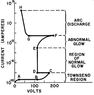
Fig. 3. Volt-ampere characteristics of a gas discharge starting with the non-self
maintaining Townsend discharge through the arc discharge.
A Low-Boiling-Point Cathode Arc is a discharge in which a heavy emission of electrons occurs from a low-boiling-point liquid in a very strong electric field. Large industrial mercury-pool rectifiers belong in this class.
7. A Summary of the Characteristics of Gaseous Discharge
The current through the gas of a gaseous conductor can be increased by increasing the applied emf or by reducing the external resistance. Figure 3 shows the change sequence which takes place in the characteristics of a gaseous tube as a result of current increase.
(Note that Fig. 3 is a continuation of the curve shown in Fig. 2.) The logarithmic ordinate (Y) axis indicates the extremely wide range of currents encountered. Since the voltage-drops specified by the coordinates on the abscissa (X) axis are functions of the type of gas used, its pressure, the material of the cathode, and the distance between the electrodes, these are intended only to convey the general nature of the variations. The portion of the volt-ampere characteristic included between points A and C has already been discussed in Sections 3 and 4. At point C, electron avalanches cause the criterion for self-maintained discharge to be attained and a normal glow discharge occurs from D to E. Further current-increase produces the abnormal-glow region in which the voltage across the tube increases with rising current. At F, the transition to arc conditions takes place with a sudden large decrease in the voltage-drop to point G. From G to H, the characteristic assumes the negative resistance nature mentioned previously.
8. The Plasma
Plasma is a region within a discharge in which the number of positive ions is substantially the same as the number of electrons, yielding a zero net charge. When a free electron whose energy con tent has come from the applied electric field collides with a gas molecule, ionization may occur. If it does not, the collision is an elastic one in which the electron does not impart much of its kinetic energy to the molecule since the latter possesses a much greater mass.
After a number of elastic collisions, the electron may eventually ionize a gas molecule; in this case, the original' electron and the freed electron share the energy in approximately equal parts.
Because of their smaller mass, the electrons tend to move out of the plasma to a greater extent than the positive ions. Many of them move to the glass walls of the tube imparting to it a negative charge of a few volts. This negative voltage will attract positive ions while it repels other electrons forming a sheath with a positive charge. Sheaths may be either positive or negative depending upon the initial charge of the body around which they form. Positive sheaths form around negative bodies and, conversely, negative sheaths form in the vicinity of positively charged objects.
The two terms -- plasma and sheath -- frequently appear in gas-tube literature. Although they have many quantitative aspects, the simple definitions given above are adequate at this time.
QUIZ
1. Define the following terms: ion; electron; proton; potential gradient; force equation, expressed in dynes.
2. What is the velocity acquired by an electron in falling through a potential of 1200 volts?
3. What velocity would a mercury ion acquire in falling through the same difference of potential as Problem 2?
4. Differentiate between velocity and momentum as it relates to the passage of particles, such as electrons or mercury ions, in an accelerating field.
5. An electron which has acquired a velocity by falling through a 10-volt difference-of-potential is injected into an area in which the retarding potential gradient is 50 volts per cm. Calculate the distance the electron will move into this area before its direction is reversed.
6. Explain a "non-self-maintaining discharge" and give an application showing its use.
7. Explain a "self-maintaining glow discharge."
8. List qualitative criteria which permit analysis of the self-maintained charge condition.
9. What is the reason that ratings assigned to phototubes always include a maximum cathode-to-anode potential figure?
10. What is meant by the terms "plasma" and "sheath" as they relate to gas tubes?