AMAZON multi-meters discounts AMAZON oscilloscope discounts
9. High-vacuum Rectifiers
To study gaseous rectifiers we must first examine the principles and faults of high-vacuum rectifiers. Then we can make an intelligent evaluation of each type.
High-vacuum rectifiers make use of thermionic emission either from a directly heated cathode (filament) or from a cathode that is indirectly heated by an enclosed heater around which the cathode, in the form of a thin cylindrical sleeve, fits snugly. (See Fig. 4A and B.) When the cathode temperature rises high enough electrons are emitted from its surface in large quantities. If there is no other electrode in the evacuated envelope, the distribution of electrons within the tube is dependent on the initial velocity and direction of the emitted electrons. The distribution of electrons within the tube is such that most will be concentrated near the cathode; some will reach the envelope wall. The negative charges deposited on the wall--as well as the electrons which swarm around the cathode-exercise a repelling force on newly emitted electrons from the cathode.
These, therefore, tend to return to the cathode causing no other measurable effects.
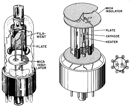
Fig. 4. Half-wave vacuum rectifiers: (A) directly heated; (B) indirectly heated.
RCA.
Now, suppose that a second conducting element is placed within the same enclosure and a source of potential connected between the emitting cathode and the new electrode. The polarity of the applied voltage should be such as to make the new electrode positive with respect to the cathode; hence the new electrode becomes an anode.
In these circumstances, electrons begin to move toward the anode in large numbers. From the electrostatic-charge point of view, we might say that the movement is explained by the attraction of unlike charges - electrons are negative and the anode is positive.
This approach certainly has merit; but it breaks down in many practical situations. It is far better to visualize the conditions in a high-vacuum tube as those which arise from the establishment of an electric field between the anode and cathode (Fig. 5).
---For a more extensive treatment of electric fields, refer to ELECTROSTATICS, edit.
by A. Schure, John F. Rider, Publisher.
A nearly uniform electric field exists between two parallel flat electrodes across which a potential has been applied. Such a field consists of electric lines of force which are considered to leave a positive point (i.e., a positive charge) on a positive surface at right angles. Each electric line of force must terminate at a positive charge at one end and an equal negative charge at the other.• Such an electric field establishes a voltage gradient "down" which an electron can fall (Fig. 1). Although it is convenient to consider electronic motion in vacuum or gas tubes as merely a matter of electrostatic attraction, the use of the field concept yields much more fruitful results.
If the dc source in Fig. 5 is replaced by an a-c generator, rectification occurs because thermionically emitted electrons can move toward the anode only when the field polarity is such as to permit them to "fall" in that direction. Current flows in the load circuit, therefore, only during each half-cycle of the ac input where the anode is made positive with respect to the cathode (Fig. 6).
10. Space-Charge Effects
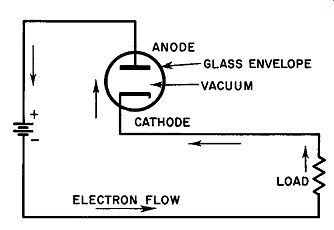
Fig. 5. A fundamental diode circuit.
For the moment let us adopt a fundamental point of view concerning the events that occur within a diode, in this case a two element, thermionic high-vacuum tube. We are interested in two separate and distinct phenomena:
1. The velocity with each electron, or a statistical average electron, reaches the anode, and
2. The number of electrons that arrive at the anode each second which, in effect, is the same thing as the number of electrons that pass a given point in the load in each second.
If a potential gradient is established between the cathode and anode, its steepness will affect only the velocity of the electrons arriving at the anode. For temperature-limited operation, this may be illustrated by an analogy: Suppose a man standing at the top of a hill starts a series of balls rolling down the incline. If he places one ball per second at the starting point, then one ball per second will reach the bottom of the hill, regardless of its slope. Obviously, the number of balls that arrive at the bottom of the incline depends only upon the rate at which the man supplies them. Similarly, the number of electrons that reach the anode per second is theoretically a function of the cathode-emission rate, not of the cathode-anode voltage gradient. Since cathode-emission rate may be shown to depend upon cathode temperature and the number of electrons per second that arrive at the anode may be considered the anode or plate current, then the following fundamental conclusions may be drawn:
1. If no other effects exist, anode current is a function of cathode temperature and
2. Anode current is independent of cathode-anode voltage.
Since experiment does not fully bear out these conclusions we know that another factor does exist. This is space charge.
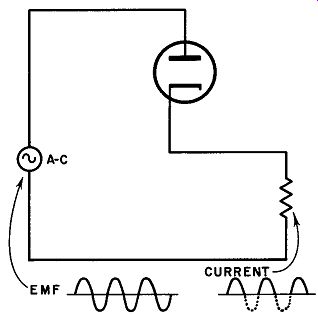
Fig. 6. Redification by a high-vacuum diode.
At high plate voltages (i.e., steep-potential gradient between the cathode and plate) , the plate current is largely independent of the difference of potential between the two elements (Fig. 7) . When the operating temperature tk of the cathode is comparatively low, the plate voltage loses its ability to affect the plate current at a rather low voltage (point A) . In the particular case shown, even a relatively low anode voltage is capable of drawing the electrons away from the cathodes as fast as they are emitted. As the cathode temperature rises and increasing numbers of electrons are emitted from its surface, the plate voltage must also be raised if the anode is to continue to attract all the available electrons (e.g., point B in Fig. 7) . Why should the three linear segments of the curve merge into one line long before reaching zero anode voltage? When the voltage is low enough - below point A - the same current flows regardless of the cathode temperature, the current magnitude being determined only by the plate voltage. On the other hand, when the plate voltage is increased to a high enough value (point B) , it no longer has any appreciable effect on the plate current which, in this case, is a function only of the cathode temperature. Why should this be?
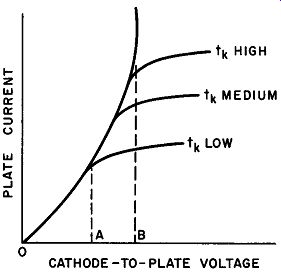
Fig. 7. Curves showing the variation of diode plate current with variations
of plate voltage and cathode temperature for a thoriated tungsten filament.
CATHODE-TO-PLATE VOLTAGE
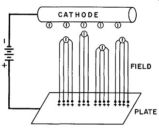
Fig. 8. Electrons in motion modify the field between the cathode and plate.
The explanation lies in the effect contributed by the electrons in mid-flight between the cathode and plate. Before the appearance of these particles in the intervening space, the electric field produced by the plate voltage consisted of lines of force which terminated at positive charges on the anode and negative charges on the cathode.
Now the lines can terminate on the moving electrons themselves (Fig. 8) . The formerly uniform linear electric field is now considerably modified. The moving cloud of electrons now form a negative "body" which terminates the lines of force; the cloud is termed the space charge. From the implications of the figure, it can be seen that the electric field around the cathode is now very close to zero so that many of the emitted electrons fall back into the cathode.
Thus, that part of the plate current emitted from the cathode which reaches the plate (plate current) is reduced by the space charge.
The space charge acts as a second negative electrode or virtual cathode in the tube near the cathode. Each time one electron arrives at the plate, the negative terminus of the particular line of force which took it there disappears so that the line now becomes avail able again to find a new terminus. This permits another electron to enter the space-charge area from the cathode, thereby establishing an equilibrium condition whose characteristic depends upon the magnitude of the applied plate voltage. This accounts satisfactorily for the common portion of the curve in Fig. 7 in which cathode temperature (t_k) has no apparent effect and in which plate voltage has complete control of the plate current. It is often said that the cathode does not directly supply the plate with electrons; that is, the cathode supplies electrons to the space-charge region, which in turn provides electrons for absorption by the plate circuit. Although this may be a play on words, it correctly brings the concept of the electric field into the space-charge picture.
11. Two Kinds of Saturation
(A) IDEAL RECTIFIER (B) PRACTICAL RECTIFIER
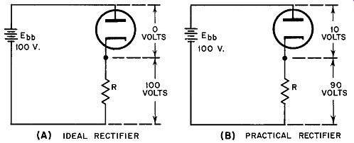
Fig. 9. An ideal rectifier (A) passes current in one direction without the
need for cathode-to-anode voltage; a practical rectifier (B) always shows a
voltage drop across its terminals.
The ideas discussed in the preceding paragraph can be summarized and differentiated in the following manner:
Temperature Saturation. If all of the electrons being emitted by the cathode of a diode at a given temperature are drawn to the plate, then no further increase of potential gradient can make any difference in the plate current. This is called temperature saturation.
Space-charge saturation. If the cathode is emitting more electrons than can be accounted for in the form of plate current, an increase of plate voltage will produce a rise in plate current. Therefore, the limiting factor at the lower plate voltage is the space charge, and the tube is said to be operating at space-charge saturation at the voltage predicated for the initial condition.
12. Voltage Drop Across High-Vacuum Rectifiers
Consider the circuit shown in Fig. 9. If there were no such phenomenon as space charge, very little work would have to be expended to accelerate the electrons from the cathode to the plate due to the tiny mass of the electrons. This almost infinitesimal quantity of work could be accomplished by a similarly infinitesimal potential difference between the two tube elements. Thus, in an ideal rectifier, the actual voltage drop across the tube would be so small as to be negligible in comparison to an applied voltage of 100 volts, for example. In this case, the entire voltage drop of the source Ebb would appear across the load resistor R and none at all across the tube.
In the presence of a space charge, however, a substantially greater amount of voltage would be required to accomplish electron transit because of the repelling effect of the space-charge cloud as explained in the previous section. Furthermore, as the plate current increases, the number of electrons in the cloud increases, and the voltage requirement rises accordingly. In a diode circuit (Fig. 9B) it is clear that the voltage across the diode terminals multiplied by the current passing through the tube measures the power loss within the tube itself; this loss manifests itself in the form of heat energy lost to the circuit.
This is one of the chief disadvantages of high-vacuum rectifiers; it is a disadvantage which has limited their use to relatively low current circuits such as one finds in radio and television receivers.
High-vacuum rectifiers are not suitable for industrial applications in which hundreds of amperes of rectified current are needed for the operation of heavy machinery.
13. Introducing Gas into the Tube
Consider a heated cathode and an anode in a glass envelope from which most of the air has been removed. A small amount of gas at low pressure is admitted. Also assume that the distance between the cathode and plate is great enough so that the mean free path of each emitted electron is quite long. (The mean free path is generally taken to mean the average distance an electron travels between collisions.) As the length of an individual electron's path increases, the probability of collision increases for conditions corresponding to a particular mean free path. Thus, as the length of an individual path increases, the chance for ionization to occur be comes greater. Assuming that the mean electron path and the applied voltage are both great enough, a large number of gas molecules will become ionized. Although the reasoning which follows applies equally to all types of ionization, for the sake of clarity it is better to assume that all the gas molecules that are struck by high speed electrons are singly ionized; that is, that one electron is liberated from each gas molecule after each collision. This leaves one singly charged positive ion adjacent to one freed electron at the instant of impact. The presence of additional electrons in the interelectrode space is not at all advantageous because these merely add to the space charge already there. The existence of ions in this space, however, presents a different aspect: these could help to neutralize the space charge and in so doing could reduce the power losses discussed in the previous section.
At the moment when the electron separates from the ion, both particles find themselves in a field of the same intensity. Also, both particles possess the same magnitude of electric charge (of opposite sign) and are therefore subject to the same accelerating force. Problem 2 (Section 2) showed that the velocity acquired by a mercury ion in a given electric field is roughly .0016 times the velocity that an electron would gain in the same field. If the gas is mercury, then, the positive ions would move slowly, comparatively speaking, toward the cathode while the electrons from the same ionization event race at high speed in the direction of the anode. Thus, long after the newly born electrons have reached the anode, the positive ions are still drifting through the interelectrode space. Now, consider that there are billions of such ions present in the vicinity of the space charge at any given time: thus it becomes evident that their joint effect can properly neutralize the space to a degree where the electrical state of the interelectrode space may be considered a plasma (Section 8) . This radically alters the characteristics of the tube as compared with that of a high-vacuum type. The differences are summarized in Section 14.
14. The Effect of Gas in a Thermionic Tube
In a vacuum diode, there is a substantially uniform distribution of electric field between the anode and the space charge region, with a virtually zero field at the cathode. With the introduction of a gas such as mercury-vapor, however, the potential distribution changes completely: the field at the cathode is quite high while that in the plasma is nearly zero. Any voltage drop which does occur in the gas tube takes place near the cathode rather than in the plasma.
Since space charge effects have been nullified, the tube drop is much smaller than that of the vacuum type. More important even than the absolute magnitude of the drop is the fact that the potential across the tube remains essentially constant over a wide range of plate currents. In a mercury-vapor tube this drop is from 10 to 15 volts. This means that rectifier power supplies utilizing mercury vapor tubes can be expected to provide appreciably better voltage regulation under varying load conditions, a very important consideration in practice. There is a straightforward explanation for this constancy: increased current results in a larger number of ions. Thus, as the space charge tends to build up with increased electron emission from the cathode, it continues to be cancelled by the greater number of positive ions formed by more frequent collisions. As one might expect, gas rectifiers exhibit a negative resistance characteristic in which the internal tube resistance is roughly proportional to the inverse of the current through the tube. Under these conditions, the anode-to-cathode voltage-drop does not change (within limits) . The maximum current obtainable in a gas-filled rectifier is the saturation thermionic emission current from the cathode plus an appreciable increment due to the high-intensity electric field at this electrode. If more current is passed through the tube than the cathode can safely deliver, the voltage drop begins to rise. When it exceeds 22 volts (or thereabouts), the cathode begins to undergo extremely heavy ionic bombardment and may begin to disintegrate.
(This effect is called cathode sputtering and the voltage at which it begins to occur is known as the disintegration voltage.) Heater and plate voltages may be applied simultaneously to a high-vacuum rectifier without deleterious effects. If this procedure is followed with a gas rectifier, the cathode may be permanently damaged. This effect is explained thus: For the first few seconds after both voltages are applied, the temperature of the cathode is much too low to supply electrons by thermionic emission. On the other hand, the anode potential produces a relatively uniform field which is just as strong at the cathode as anywhere else in the enclosure. This condition encourages a self-maintained discharge with is accompanying intense bombardment of the cathode by positive ions of large mass. Since mercury-vapor rectifiers use oxide-coated cathodes - these are usually nickel sleeves coated with barium and strontium oxides in the proper proportion to yield a plentiful supply of electrons at low temperature - such cathode sputtering will cause the oxide to flake off causing permanent injury to the cathode structure.
15. Mercury-vapor Rectifier Ratings Current Ratings. All types of gas-rectifier tubes are rated in terms of average current. This is the maximum continuous current which the tube can handle without overheating, the average to be taken over a given period of time as recommended by the manufacturer. For example, a small mercury-vapor rectifier such as the FG-190 is rated at an average current of 1.25 amperes continuously.
A second important current rating is the permissible peak current which is defined as the maximum current that should be permitted through the tube in each conducting cycle; for the FG-190, the peak current rating is 5.0 amperes. Some tube types are also rated for maximum surge current which is the peak current for a very definitely specified period of time. Thus, the surge current rating of an FG-190 is 20 amperes for 0.1 second. It is important to remember that operation at or near the surge current rating - for even a short time -may seriously reduce tube life.
Voltage Ratings. During the portion of the a-c input cycle when the rectifier is not conducting, the anode is negative with respect to the cathode and operates like a non-thermionic type of discharge tube. Maximum inverse peak voltage is the highest voltage the tube will stand in an inverse direction without the possibility of flashback.
The maximum peak inverse voltage rating of an 866-A mercury vapor rectifier - a very popular type for low power applications - is approximately 10,000 volts. The complete set of ratings for this tube follows:
RATINGS - MERCURY-VAPOR RECTIFIER 866-A
Average current ...... 0.25 ampere
Peak current .... 1.0 ampere (per cycle)
Surge current .. 9.0 ampere for 0.1 second
Maximum Inverse Peak Voltage ... 10,000 volts (approx.)
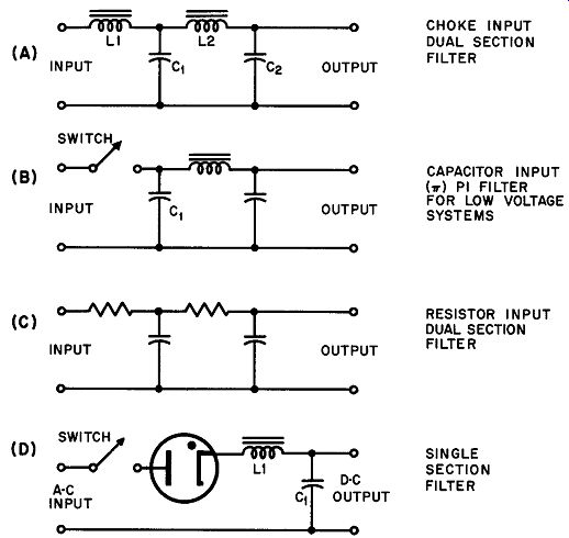
Fig. 10. Types of filter networks. --- CHOKE INPUT DUAL SECTION FILTER CAPACITOR
INPUT (v) Pl FILTER FOR LOW VOLTAGE SYSTEMS RESISTOR INPUT DUAL SECTION FILTER
SINGLE SECTION FILTER.
Aside from those factors we would expect to influence the maximum inverse peak voltage rating of a gas tube (type of gas, gas pressure, tube geometry, etc.), three other important influences must be taken into account.
(1) The frequency of the applied voltage. At high frequencies, the likelihood of flash-back is increased since the gas may not have time to de-ionize completely before the next half-cycle arrives, (2) The current flowing in the tube. Heavier currents encourage earlier flashback since such currents produce large numbers of ions, some of which may still be present when the inverse portion of the cycle is applied, (3) Condensed mercury temperature. There is always a small pool of liquid mercury in a mercury-vapor rectifier; this pool is the source of the vapor itself. As the liquid heats, the gas pressure is increased and the maximum inverse peak voltage the tube can stand diminishes. In the case of the 866A, for instance, the maximum inverse peak voltage rating is 10,000 volts or better when the temperature of the condensed mercury is below 50° C. Should the temperature of the condensed mercury rise to 80° C due to a change in ambient conditions, the maximum inverse peak voltage drops to approximately 5500 volts.
16. Filters for Mercury-vapor Rectifiers
The output voltage of a rectifier is pulsating dc having a large ac component. Filter networks consisting of capacitors and iron core inductors (chokes) are most frequently used to minimize this component, although resistors are sometimes used in conjunction with or to replace the chokes. Several representative filter systems are shown in Fig. 10.
The network of Fig. 10A is known as a series-inductance input or choke input arrangement and is the type generally recommended for use with gas rectifiers. C1 is in an uncharged condition before power is applied (Fig. 10D) . At the instant that the switch is closed, a charging current flows into C1 through the rectifier. Series inductance L1 limits the magnitude of this surge current to a safe value for the particular rectifier in use by virtue of the L-C time constant of these components.
In a straightforward capacitance-input filter such as that of Fig. 10B, the only resistance between the rectifier and C1 aside from the connecting wires is that of the rectifier tube. Consequently, upon closure of the switch, the surge current may well exceed the safe rating of the tube by several hundred percent. The filter network shown in Fig. 10C illustrates the arrangement in which resistors replace chokes. Although this system may be designed for use with gas rectifiers, it has other disadvantages: the resistors must be rated at sufficient power dissipation for the load, and the voltage drop across the resistive filter components may become excessive even with reasonable loads, thereby nullifying the principal advantage of the mercury-vapor tube - low voltage drop.
QUIZ
1. Explain the process of rectification in high-vacuum rectifiers.
2. What is space charge? How does it affect anode current? What other factors affect anode current?
3. List and explain two types of saturation.
4. Explain the power loss within a high-vacuum rectifier and show why this constitutes a major disadvantage of this type of tube.
5. Explain the ionization process that takes place when gas is introduced into the tube.
6. What is the effect of gas in a thermionic tube--tube with respect to the size of the voltage drop across the tube? Why is this so?
7. What are "cathode sputtering" and "disintegration voltage"?
8. Heater and plate voltages applied simultaneously to a gas rectifier tube may permanently damage the cathode. Why?
9. Typical mercury-vapor rectifier ratings might include: average current; peak current; surge current; maximum inverse peak voltage. What is meant by each?
10. Draw a typical filter used with mercury-vapor rectifiers.