In multi-speaker systems in which specialized speakers are used for different frequency bands it is necessary and desirable to segregate these different bands of frequencies into the respective speakers de signed to handle them. As discussed in the previous chapter, this segregation of the various bands of acoustic energy insures optimum utilization of audio power, resulting in better overall performance of the system.
Networks are composed of elements which allow to pass, or per vent from passing, certain bands of frequencies. A capacitor will pass high frequencies and block low frequencies. Therefore, it is to be found in high-pass filter sections (Fig. 7-1). A choke or inductor will block high frequencies and pass low frequencies. It is therefore found in low-pass filter sections. If both a low-pass element and a high-pass element are in series in a single branch of a circuit, a band of frequencies is passed. The band has its low frequencies restricted by the high-pass element and its high frequencies restricted by its low pass element. Those frequencies in between these two restricted ends become the "pass band." From these simple concepts we may derive almost all the popular networks.
-----------------------
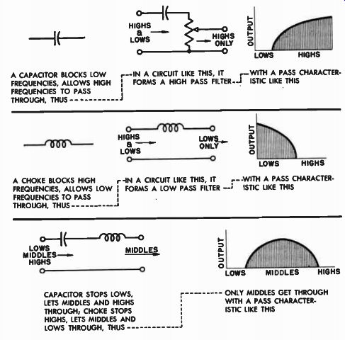
Fig. 7-1. Networks are composed of elements which allow to pass, or prevent
from passing, certain bands of frequencies. A CAPACITOR BLOCKS LOW FREQUENCIES,
ALLOWS HIGH FREQUENCIES TO PASS THROUGH, THUS -------- A CHOKE BLOCKS HIGH
FREQUENCIES, ALLOWS LOW FREQUENCIES TO PASS THROUGH, THUS --------- CAPACITOR
STOPS LOWS, LETS MIDDLES AND HIGHS THROUGH; CHOKE STOPS HIGHS, LETS MIDDLES
AND LOWS THROUGH, THUS ONLY MIDDLES GET THROUGH WITH A PASS CHARACTER ISTIC
LIKE THIS
------------------
High-Pass Filter Keeps Lows out of Tweeter
The frequencies at which the filter elements become active depend upon their particular electrical values, and the effectiveness of the network as a whole depends upon the number of elements in the network. Applying the above concepts, let us lay out the various types of networks, and apply each to a particular situation. The simplest popular network is the high-pass filter. This type of network is employed where there is an existing speaker or speaker system, to which a tweeter is to be added. The high-pass filter is connected to the tweeter as shown in Fig. 7-2. The high-pass element blocks the low frequencies from getting into the tweeter, allowing only a certain range of high frequencies to pass through, the lower limit depending on the size of the capacitor. A smaller capacitor will pass the highs, with some middles. A large capacitor will pass the highs with more middles.
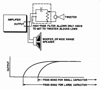
Fig. 7-2. Method of connecting high-past filter to amplifier and tweeter.
Low-Pass Filter Keeps Highs out of Woofer
If we desire to keep the high frequencies out of the woofer (and pass them to the tweeter, where they will be more efficiently reproduced), we put an inductor into the woofer circuit, as shown in Fig. 7-3. Such an inductor (choke) will be a low-pass filter. Now the woofer will reproduce only a certain range of lows, as determined by the size of the choke. A large choke will pass fewer highs, a small choke will pass more highs. The choice of the choke will therefore determine the limit of the low pass. By the addition of the choke to the woofer circuit we have converted the simple high-pass arrangement shown in Fig. 7-2 to a two-way system with a crossover network, because now the high-pass band and the low-pass band cross over at some particular frequency.
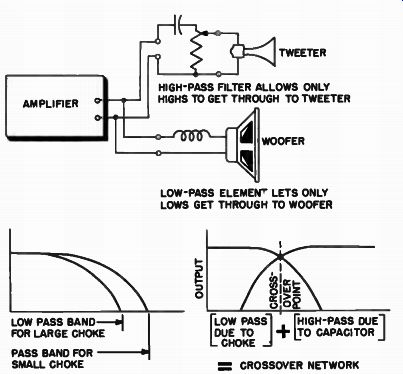
Fig. 7-3. Low-pass filter plus high-pass filter form a crossover network.
(Network shown has a 6 db per octave attenuation.)
Obviously, the frequency at which they cross over will be determined by the electrical values of the filter elements involved.
Crossover Networks are Composed of High-Pass, Low-Pass, and Band-Pass Filters
The problem of constructing a three-way crossover network is only slightly more involved. Figure 7-4 illustrates a simple three-way network. As before, the response of the woofer is cut off in the high end by the low-pass choke. The middle frequency band has its lows limited by the high-pass capacitor, and its highs limited by the low pass choke, thus allowing only the middle frequency band to be passed.
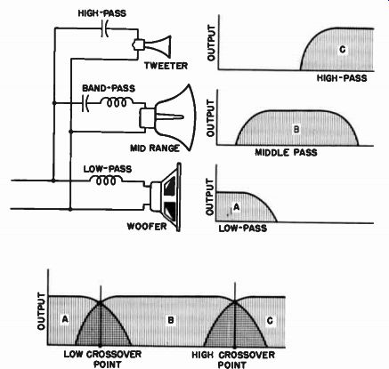
Fig. 7-4. A three-way crossover network is made by combining separate
pass band elements that individually cover different sections of the
band.
The tweeter reproduces only the highs passed on to it by its capacitor.
The characteristic bands of output of the three sections cross each other in succession so that we have in this three-way network a low crossover point between the woofer and midrange sections, and an upper crossover frequency between the middle and high treble frequencies. In this case, as in the previous one, the crossover points will be determined by the electrical values of the filter crossover elements involved.
Number of Filter Elements in One Circuit Determines Attenuation Rate
Crossover networks have another characteristic in addition to their low-, high-, or pass-band features. They have an "attenuation rate" at the crossover point. The attenuation rate simply signifies how decisive the filter action is. Figure 7-5 shows the high-pass filter response with two different attenuation rates, a slow one and a fast one.
A sharp cutoff filter may be made by combining two filter elements of opposite types (a high-pass element and a low-pass element) in the same branch circuit with one element in series with the speaker, the other in parallel with the speaker. In Fig. 7-6 is shown a sharp cutoff high-pass filter. The series capacitor will allow high frequencies to get into the tweeter, but the choke across the tweeter, being a low pass element, will detour around the tweeter the lower frequency end
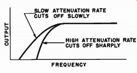
Fig. 7-5. High-pass characteristic with two different attenuation rates.
of the high frequency band passed on by the capacitor. The highs, however, will not be bypassed by the choke, so they will continue to go into the tweeter. Accordingly, by adding a low-pass element across the tweeter, we have effectively sharpened the high frequency pass band that the tweeter sees. We have increased the attenuation rate of the network. In a similar fashion the attenuation rate of a low-pass filter …
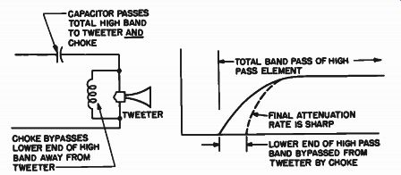
Fig. 7-6. A sharp cutoff high-pass filter is made by adding a low-pass
element across the tweeter circuit.
… may be sharpened by shunting the load with a high-pass element as shown in Fig. 7-7. By combining these sharper cutoff high-pass and low-pass elements into the previously discussed filter circuits we obtain sharp cutoff two-way networks, as shown in Fig. 7-8, or three-way networks, as shown in Fig. 7-9.
Sharpness, or attenuation, of a crossover network is usually given in terms of db's per octave in the crossover region. The term db is an abbreviation for the word decibel. The decibel scale provides a convenient way of compressing large changes into small changes so that they may be easily handled and so that they bear a closer relationship to the manner in which the ear responds to the intensities of sounds.
Precisely, it is a "logarithmic ratio." (See Fig. 7-10.) Every time power is doubled, we say there is a 3-db gain. If the power has doubled itself 10 times, then there has been a 30-db increase. If the voltage has …
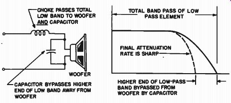
Fig. 7-7. A sharp cutoff low-pass filter is made by shunting a high-pass
element across the woofer circuit.
…doubled itself, we say there is a 6-db gain. Thus, if the voltage has doubled itself 10 times, there has been a 60-db gain. Reference to Fig. 7-10 will show how conservative these db values are in relation to the actual growth of the power or voltage figures.
Thus, getting back to the network, if the characteristic of the circuit is such that the voltage across the speaker branch of the network drops to one-half that of the total voltage input across the network in a space of one octave, causing a power drop to one-quarter of the original power, the attenuation rate is 6 db per octave. If the voltage drops to one-quarter in the same octave span, causing a power drop to one sixteenth of the original power, there is a 12 db per octave roll-off.
(Refer to Fig. 7-11.) Obviously, the 12 db per octave roll-off is the sharper, and the 6 db the slower. The former is produced by the type of network shown in Fig. 7-8, and the latter by the network in Fig. 7-3.
The actual design conditions for a particular network are governed by the choice of crossover frequencies and the attenuation rate desired.
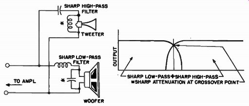
Fig. 7-8. Sharp cutoff filter sections as shown combine to produce
a sharp attenuation rate (12 db per octave) crossover network. Asterisks
show added bypass elements that convert network from 6-db to 12-db type.
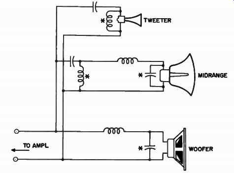
Fig. 7-9. A three-way network arranged for 12 db per octave attenuation
at the crossover points. Asterisks indicate the added bypass elements
that convert the network from 6-db to 12-db type.
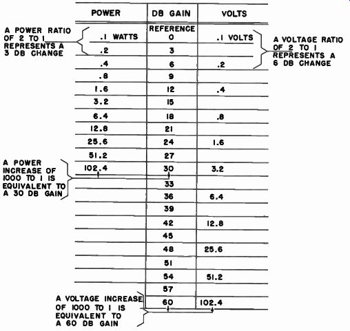
Fig. 7-10. The decibel scale is a means of compressing large changes
in physical quantities into small numerical changes.
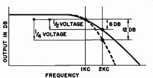
Fig. 7-11. When voltage drops to 1 / 2 the value of the voltage at
the crossover frequency, the attenuation is 6 db; if it drops to 1 /
4, the attenuation is 12 db. If this drop takes place in a span of one
octave, there is either a 6 or a 12 db per octave attenuation.
These factors, in turn, depend upon more subtle considerations concerning the type of speakers that make up the system, and what is actually desired from the system. Therefore, we shall now give full consideration to those factors which govern the choice of network, and then we shall present some practical design data.
Networks Conserve Audio Power
In breaking up the total reproducible spectrum into various bands and then directing these bands into separate specialized speakers, we may realize a great degree of conservation of audio power. Let us refer back to the simplest system of Fig. 7-2, where the tweeter is connected across the audio signal line through a simple high-pass filter.
Let us assume, however, for the sake of illustration, that the capacitor in this high-pass filter has been eliminated. This condition of direct parallel operation of the woofer and the tweeter means that the amplifier power now will be equally divided between woofer and tweeter (if they have the same impedance). If a total of 10 watts of audio power is available from the amplifier, the woofer will take 5 watts of full frequency range power and the tweeter will take 5 watts of the same full frequency range power. Obviously, the woofer, which is a low frequency device, will not be able to do justice to the high frequencies; nor will the tweeter, which is a high frequency device, be able to do justice to the low frequencies. Since the total power is equally divided between the two units, half the high frequency power is lost in the woofer, and half the low frequency power is lost in the tweeter. What is more, the omission of the high-pass filter may result in overloading the tweeter if this loudspeaker is not able to handle the additional power that would now be applied to it.
Now let us put in the high-pass filter. Immediately, the low frequency power formerly lost in (or possibly overloading) the tweeter has been stopped from going into this blind alley. Instead, the low frequency power blocked from entering the tweeter must look for another route. It must now join the rest of the low frequency energy going directly to the woofer. Essentially, then, the woofer now gets twice the audio power it was receiving before the insertion of the high pass filter in the tweeter circuit. As a result, the woofer now plays louder for the same power output from the amplifier. If, however, one wished to maintain the previous listening level, the amplifier gain control must be turned down, resulting in more conservative operation of the amplifier and consequent reduction of distortion.
We may go one step further, and prevent the highs from being lost in the woofer, by inserting the low-pass choke into the woofer circuit, as in Fig. 7-3. This blocks the highs from the woofer but lets the lows through. Accordingly, we now realize a saving in high frequency power, for the highs, blocked from entering the woofer, naturally take the path of least resistance and go to the tweeter. The tweeter now receives twice as much treble energy for the same setting of the amplifier. Thus we see that a well-designed crossover network, usually hidden away somewhere where it cannot be seen, in its own unobtrusive way goes far toward increasing the available power from the amplifier, by simply routing the energy where it will do the most good.
Networks Reduce Intermodulation Distortion
Of equal importance to the matter of power utilization, however, is the fact that a well-designed crossover network will improve the cleanness of the audio reproduction by minimizing intermodulation distortion. Let us go back to the previous example and briefly examine the tweeter operation with and without the low frequency isolating element. With the isolating capacitor left out of the tweeter circuit, electrical currents of both low and high frequencies are sent through the tweeter voice coil. Even though the tweeter diaphragm may have a high resonant frequency, it still has a tendency to vibrate below its resonant point, especially if these low frequencies are large in magnitude. Thus, the small tweeter diaphragm tends to bounce back and forth in its magnetic circuit under the strong low frequency impulses. However, because the diaphragm is small and is coupled to the horn (which will not transmit low frequencies) it will accomplish no useful acoustic purpose. On the contrary, it deteriorates the high frequency performance of the tweeter by causing the small high frequency vibrations of the diaphragm to be carried along on these spurious and excessive low frequency vibrations of the diaphragm. Hence, the irregular and non linear low frequency vibrations of the diaphragm modulate the high frequencies, causing intermodulation distortion. However, if the high pass element is now inserted in the tweeter circuit, the low frequencies do not enter the tweeter; the diaphragm moves only under the insistence of the high frequencies and they radiate cleanly, and free of low frequency effects. Thus, in addition to their audio power saving characteristics, crossover network serve to improve the overall cleanness of reproduction of the segregated bands of frequencies.
Crossover Characteristics
Determined by Network Plus Speakers
The success with which a crossover network accomplishes its purpose is dependent not only upon the network design itself, but also upon the speaker components with which it must operate. Those factors which determine how well the network operates are the crossover points, the attenuation rates at the crossover points, and the compatibility of these two factors with the corresponding ones for the speakers of the system.
A 6-db attenuation rate crossover network will separate the frequencies at the crossing bands at a moderate rate but with considerable overlapping areas between the two different bands. On the other hand, the 12-db attenuation rate network will separate the channels more sharply and with less overlapping area between the two. One system is not necessarily better than the other. What determines the choice of system, as far as crossover points and attenuation rate are concerned, is the natural characteristics of the speakers that constitute the system.
All speakers have their own natural high frequency roll-off characteristics and low frequency cutoff characteristics. These speaker characteristics have to be integrated into the network system for compatibility of their attenuation and roll-off characteristics.
The choice of a crossover frequency is not determined by any hard and fast rule. The fact of the matter is that, for a given set of speakers with wide overlapping areas, there may be a wide choice of crossover frequencies. The example given at the end of the previous section(Fig. 6-13), where there was an adjustable crossover high-pass filter with a tweeter capable of covering a wide band, was a case in point; the actual crossover point could be chosen on a listening basis rather than on a purely electrical basis. Of course, once the listening objective has been established, the electrical crossover characteristics may fall right into place if the networks are of the adjustable type. If we let the matter of listening preference go for the moment, however, we may examine the more rigorous acoustic basis upon which the crossover point may be determined.
At Crossover Point, Speakers Should Have Equal Output
The first criterion of choosing the crossover point of a network is that at the crossover frequency chosen, the speakers have equal acoustic output. This simply means that the speakers must have a reasonable area of overlapping response within which the network may be applied without causing holes in response. Thus at the crossover point the speakers will both have equal acoustic output, but will then be attenuated on either side of the crossover point as dictated by the network design. The sharpness of the attenuation rate of the network, plus the natural attenuation of the speakers themselves, will naturally determine the sharpness of separation of the various acoustic ranges of operation of the speakers. This acoustic separation raises the question of the auditory sharpness of the separation of the individual speakers of the system as far as the listener is concerned. The present acceptance of stereophonic sound in professional entertainment houses is a clear indication that this new dimension is an entirely desirable one for modern sound reproduction. Any approach to such panoramic sound in the home may be valued by the listener who wants some measure of concert hall separation of instruments in his reproducing system.
While it is true that separation of the music in sharp frequency bands is not the same as separating the music of one instrument from the other, there is some feeling, synthetic though it may be, that at least some of the instruments have been spatially stretched out into a greater listening area, giving a substantially greater acoustic perspective to their reproduction. For people who prefer this separation, sharp separation of the speaker ranges is desired and the network should have a steep attenuation rate to provide this sharp degree of separation.
On the other hand, where the listener prefers more blended sound, more unity to the overall reproduction, he will require that the speakers of the system do not separate sharply but rather that they overlap to some degree. Accordingly, the network characteristic for this application will be one of moderate attenuation rate.
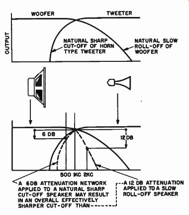
Fig. 7-12. The sharpness of the crossover characteristic is determined
both by the network and by the speakers of the system. -------- A 6DB
ATTENUATION NETWORK APPLIED TO A NATURAL SHARP CUT-OFF SPEAKER MAY RESULT
IN AN OVERALL EFFECTIVELY SHARPER CUT-OFF THAN ---------A 12 DB ATTENUATION
APPLIED TOA SLOW i ROLL-OFF SPEAKER
Attenuation Rate Determines Sharpness of Acoustic Separation Between Speakers
In general, then, the problem of slow attenuation rate versus fast attenuation rate in networks is similar to the problem of the individual multi-speaker system types compared to the integrated pack aged units. The listener who wants to be on stage" and hear close-ups will choose the multi-speaker system made up of individual units, for then he will have clean separation of instruments. He will also choose steep attenuation rates for his networks. The listener who wants to sit way back in the family circle and hear overall sound pictures will choose the integrated coaxial and triaxial type speakers and slow attenuation rates for the network.
As previously stated, the system crossover characteristic attenuation rate is a combined function of the network attenuation rate plus the attenuation rate of the speakers themselves. This interdependence of the network and speaker attenuation characteristics is, however, only partly related to the problem of overlapping areas. Thus, as is shown in Fig. 7-12, two speakers may have the same overlapping area of equal level, but one may have a much steeper cutoff characteristic than the other. It is therefore probable that a fast cutoff speaker with a 6 db per octave network would provide a sharper crossover characteristic than a slow cutoff speaker with a 12 db per octave network. A horn type reproducer, such as a compression tweeter, is essentially a sharp cutoff radiator with virtually no usable output below its theoretical cutoff frequency. On the other hand, a cone reproducer, such as a woofer, may have useful energy output extending into the middle high frequencies. It is quite apparent, then, that even without the benefit of the crossover networks, the horn to some extent provides its own crossover networks, while the cone remains relatively unaltered. There fore, if the tweeter horn system is now integrated with a 6 db per octave crossover network, the combined attenuation will be greater than the cone type system operating with a 12 db per octave network.
Accordingly, the attenuation rate of the network must be integrated with the speaker characteristic not only for equal output level at the crossover point, but also for compatible attenuation rates of the net work and speaker combination.
If relatively long overlapping areas of performance between adjacent speakers are desired, the combined network-speaker attenuation characteristic will be chosen on a slow basis. If sharp distinct separation of adjacent speaker performance is desired, then the combined network-speaker attenuation characteristic will be comparatively steep.
Speaker Enclosures Are Acoustic Crossover Elements
It will be realized that baffle arrangements are actually acoustic crossover elements, as is, for instance, the sharp cutoff horn of the tweeter. Actually, all baffles are acoustic crossover elements, and as such will be treated more specifically in the section on baffles and enclosures. For the present, however, it is important to keep in mind the interdependence of the baffle as an acoustic crossover element, the natural roll-off or cutoff of the speakers themselves, along with the network characteristics, determining the sharpness of the crossover system as a whole.
As for the crossover network itself, sharp network attenuation specifically means sharper separation of the chosen bands of frequencies.
Accordingly, there will be less interaction of the lower band of frequencies upon the speaker operating on the upper adjacent band (as illustrated in Fig. 7-13). With less interaction between the bands, there will be cleaner reproduction of the upper frequencies, because the disturbingly large lower frequencies have been eliminated from the treble speaker.
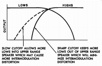
Fig. 7-13. The sharpness of the attenuation rate of the system will
deter mine the degree of intermodulation distortion which may occur
if the speakers are not perfectly linear. SLOW CUTOFF ALLOWS MORE LOWS
INTO UPPER RANGE SPEAKER WHICH MAY CAUSE MORE INTERMODULATION DISTORTION
D -----------SHARP CUTOFF KEEPS MORE LOWS OUT OF UPPER RANGE SPEAKER
WHICH WILL MINI. MIZE INTERMODULATION DISTORTION
Networks Affect Transient Response
There is another type of distortion, called transient distortion, which is a measure of the ability or lack of ability of the loudspeaker to faithfully follow the suddenly applied impulse type of tones, and to let go of these tones as dictated by the signal itself. The ability of the loudspeaker to function in this manner was treated in the previous chapter, where it was pointed out that a heavy magnetic gap flux would tend to minimize such transient distortion. In the present considerations, however, we are going to analyze the part that the crossover network plays in introducing transient distortion into the reproducing system. Transient distortion in networks is introduced at the crossover point region due to too sharp an attenuation rate. As we have seen, a sharp attenuation rate is obtained by the use of several sections of filter elements in a speaker circuit, whereas low attenuation rate is the result of a minimum of filter elements. Where a multiplicity of such elements exists, two effects take place.
First there may be phase shift of the various component frequencies that make up a complex sound. In any electrical network, phase shift of the signal always occurs as the signal passes through a single filter component. In general, the more components the more drastic the phase shift. If these frequencies thus become electrically too far displaced from their original relationships, they may not recombine acoustically into the same pattern. As a result, the final tone may not have the same overall sharp form as the original; transient distortion will thereby have been introduced.
The second effect of steep cutoff networks is their tendency to cause "ringing." Complex networks are made up of components that form resonant circuits. Being resonant they may be "shock excited" at certain frequencies, causing a momentary self-oscillation or ringing for some short, but appreciable, time after the original signal has been removed. On the other hand, the more simple networks, although not producing as clean a demarcation between the various bands, are less subject to these types of distortion. For this reason, present practice is to avoid networks that have an attenuation rate in excess of 12 db per octave. For modern loudspeaker practice, 6 db and 12 db per octave attenuation rates provide adequate control, and offer ample choice to match the particular characteristics desired for most reproducing systems. Before we take up the matter of the actual construction of networks by the hobbyist, it will be of benefit to examine commercially available networks designed for multi-speaker systems.
Packaged Networks for Packaged Systems
There are available commercial networks of many designs and for many applications. Many manufacturers recommend specific networks for use in conjunction with their engineered and matched combinations of speakers for a multi-speaker system. Such recommended "system" networks are shown in Figs. 6-10, 6-11, and 6-12. Of great value in any network application to multi-speaker systems is the incorporation of controls for adjusting the presence and brilliance of the system. As will be recalled from section 6, the "presence" of a system resides in the middle frequencies, and "brilliance" in the upper treble region. For adjustment of these factors, controls are inserted into the electrical output of the network that will ultimately feed the midrange and the tweeter reproducer. Thus, where these controls are readily available to the listener, there is a sort of "acoustical baton," which permits the listener to balance his "home orchestra" to best suit his tastes.
Adjustable Networks Permit Hobbyist to "Tune" System to his Preference
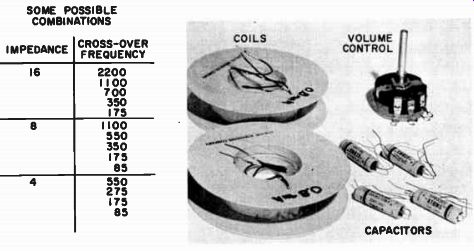
Fig. 7-14. Network kit that may be obtained for constructing network.
Individual coils or kits are available for the above tabulated requirements.
(Courtesy General Apparatus) -------- SOME POSSIBLE COMBINATIONS
For the hi-fi enthusiast who chooses his own components, however, there is a choice of crossover networks or network components to enable him to get the most out of his system, or to enable him to experiment with his system at will. Kits of network elements, such as that shown in Fig. 7-14, are made available for the constructor who knows exactly what his requirements are for impedance of the system speakers, crossover points, and attenuation rates. The assembly of these components is fairly straightforward.
There is also available a very convenient already built multi-purpose network design that offers the hi-fi constructor a wide choice of network parameters with which to work. This network package is shown in Fig. 7-15. It consists of two independently complete but also complimentary network systems by means of which it is possible to select any of a number of crossover points at any of the common speaker impedances, plus a choice between 6 db or 12 db per octave attenuations. By selecting the proper designated terminals on the terminal board of the network, he may readily make his choice of the various conditions of operation. The short table accompanying the photograph of these multi-purpose networks shows the versatility that has been built into the networks to accommodate any selection of speakers.
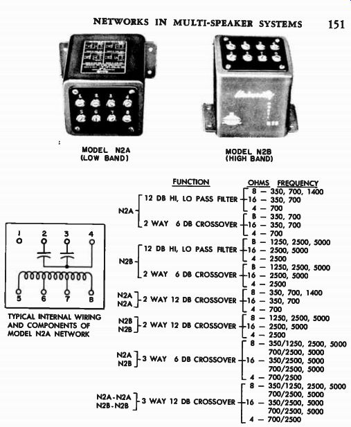
Fig. 7-15. Crossover units which permit the wide selection of crossovers,
attenuation rates, and impedances shown from the two single models.
( Courtesy University).
Adjustable Networks Eliminate Obsolescence of Components
However, there is a more important asset in such diversified net works, and that is the elimination of the obsolescence factor. If the constructor has begun a progressive speaker expansion program, a single network may meet his immediate need. As his system grows, he may simply add the complementary network to achieve a three-way system, or to realize steeper crossover characteristics at the crossover points if he desires it. Let us assume that one's original system was a 15-inch woofer in a bass-reflex enclosure, with a tweeter crossing over at 750 hz, this crossover being accomplished by the type N2A network shown.
After a couple of years of indoctrination into the hi-fi family, the listener may decide to expand his two-way system to a three-way system, using the same woofer and tweeter, but adding a cone speaker as a midrange reproducer. (See Fig. 7-16.) He may now use the N2A as the low crossover network and drop the crossover point from 700 to 350 hz by simply connecting the proper terminals on the network.
Then he may add the type N2B network to provide the upper crossover between the midrange cone speaker and the tweeter. Since the tweeter originally went down to 700 hz, and since the cone speaker will probably go well up into the treble region, there will be a large overlapping area, in which the N2B network may be used to find the crossover point best suited to the system. Universal networks of this type are a sort of master key to multi-speaker system design, allowing for obsolescence-free system expansion planning and for a choice of personal operating conditions.
The Home-Constructed Network There are, however, many hi-fi hobbyists who find pleasure in building as much of their own equipment as they possibly can. For these, we will now offer a simple but concise method of building a workable crossover network.
The design of a crossover network is based on three factors: (a) speaker impedance; ( b ) crossover frequency; and (c) attenuation at the crossover point. These factors determine the electrical size of the capacitors and inductors that make up the various branch circuits. The chart in Fig. 7-17 provides a simple means of selecting the proper value of components for a chosen crossover frequency between any two speakers whose frequency ranges overlap. The chart also presents values for either a 6 db or a 12 db per octave attenuation rate. It is not limited in any way to the number of branch circuits that may be used in the system. It may be applied to a two-, three-, four-, or even five-way system, if desired. This versatility is accomplished by taking the speakers one by one, starting from the lowest frequency range, and selecting the proper constants to cross that speaker with the next adjacent speaker in the frequency range. Then, in a like manner, the constants are chosen to cross this second speaker with the third speaker. An example will illustrate its application.
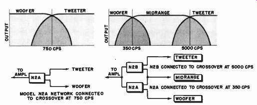
Fig. 7-16. The multiple crossover frequencies available from the commercially
available networks permit system expansions without obsolescence of
equipment.
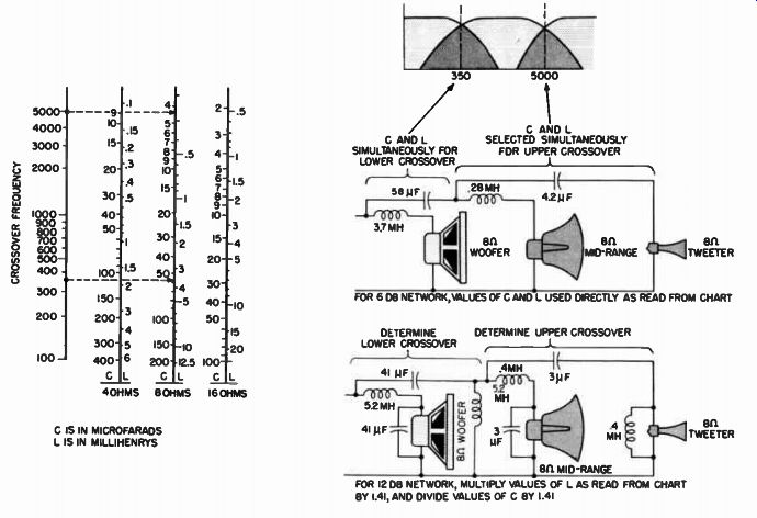
Fig. 7-17. Universal chart for finding component values for crossover
networks with either 6-db or I2-db attenuation, tot systems of 4, 8,
or 16 ohms impedance.
Sample Network Design
Let us design a network for a three-way system, such as that shown in Fig. 7-4, with crossovers at 350 and at 5000 hz, for speakers of 8-ohm impedance, and to have a 6 db per octave roll-off. (See Fig. 7-17.) We are first concerned with the woofer and the speaker adjacent to it, the midrange speaker. The crossover frequency is to be 350 hz. Locate 350 on the frequency scale. Extend a horizontal line to the right until it intersects the proper CIL line, which gives the electrical constants necessary for the low frequency speaker circuit - 3.7 millihenries for the coil and 58 microfarads for the capacitor in the lead to the midrange speaker. Incidentally, if we were concerned only with a two-way system (as shown in Fig. 7-3) to cross over at 350 hz, these two values would give us the complete design of the network. However, since we are building a three-way network, we must now deal with the second crossover point.
To select the constants for this upper crossover frequency of 5000 hz, we regard the midrange speaker as the lower speaker. Entering the chart from the 5000-hz mark, we again proceed to the 8-ohm C/L line and find the value of the choke (.28 millihenry) to be put into the lower speaker circuit, and the value of the capacitor (4.2 micro farads) to be put into the upper speaker circuit. The network design for a system to cross over at 350 hz and 5000 hz with 6-db attenuation is now complete.
To design a 12 db per octave network for a three-way system we proceed exactly as above to select the necessary capacitor and coils, but this time we apply the factor of 1.41 as specified by the chart. The value of L is multiplied by 1.41 and the value of C is divided by 1.41.
Thus we have obtained all the necessary electrical values for the making of the crossover network.
Choosing the Type of Capacitor
The capacitors for the network must be bought; they cannot be made by the home constructor. The smaller capacitors, those of 4 and under, may be of the paper variety. However, they should be a good grade, or they may become leaky (low in leakage resistance across their terminals.) This will result in poor network response. Preferably, these capacitors should be of the oil-filled paper type, usually obtainable in the bathtub variety. These are self-healing in case of internal rupture and do not age or deteriorate. The alternating voltage rating of the capacitors need not exceed 50 volts if the network is designed for the common speaker impedances of 16 ohms and under. Where larger values of capacitance are required, the cost of the unit may be rather high and its size large if the oil-filled type is specified. Fortunately, it is possible to obtain good performance and high capacitance by using "non-polarized" electrolytic capacitors.
Normally, an electrolytic capacitor is marked "minus" and "plus" on its terminals, and this is how it is intended to be connected when used as a filter in d-c power circuits. This is the polarized type. The non-polarized type is actually two of these polarized capacitors in one case, internally connected in a series circuit ("back to back") with their similarly polarized terminals connected together. This results in a capacitor that may be put across a line carrying audio voltage. Such non-polarized electrolytic capacitors, rated in very large capacitances, are readily obtainable from radio supply houses at reasonable cost.
If the constructor wishes, he may make his own non-polarized electrolytic combination by simply connecting two equal electrolytic filter capacitors back to back. In making this combination it must be remembered that the effective capacitance of two capacitors in series is equal to only one-half that of a single unit. Thus, to obtain an 8 ¡if non-polarized capacitor, two 16 u-f polarized capacitors may be connected in series as shown in Fig. 7-18.
However, there is a precaution that should be exercised when a small electrolytic capacitor is used for a particular crossover point and this crossover element is to function out to the very end of the tweeter
Fig. 7-18. Polarized (electrolytic) capacitors may be connected back-to back to form a non-polarized capacitor. It should be noted that the total capacitance of the combination is equal to one-half of a single unit.
spectrum. In this case one-half the total capacitance in the circuit should be provided by the electrolytic type and one-half by the paper type, where the total capacitance of these two is equal to the value required to obtain the desired crossover frequency. The paper capacitor is wired in parallel with the electrolytic. The reason for this precaution is that the electrolytic capacitor becomes less effective as a by-pass element at the higher frequencies. This is a result of its higher power factor and increased impedance (it may actually become inductive) at these higher frequencies.
Making the Coils
The inductor may be made by winding onto the bobbin shown in Fig. 7-19 the number of turns required for the specific inductance.
The bobbin may be made of wood or any other non-magnetic form rigid enough to support the necessary turns of wire. It is not necessary that the wire be accurately layer-wound. The coil may be random wound, provided the winding space is evenly filled up.
Fig. 7-19. Chart for winding inductors for crossover components as read from universal nomograph of Fig. 7-17.
Volume Controls may be Inserted in Speaker Lines
Volume controls may be inserted between the terminal of the network and the speakers for the purpose of controlling the presence and brilliance of the system. (See Fig. 7-20.) These controls may be either the simple potentiometer type, or the more elaborate constant impedance pad types. The potentiometer has the advantages of simplicity in installation and of economy. The value of the potentiometer should be at least five time the value of the impedance of the speaker to which it is to be connected. Thus, if the speaker is 8 ohms, a 50-ohm potentiometer will be suitable. L- or T-pads may also be used as volume controls. They have the advantage of maintaining more constant impedance on the amplifier as the level of operation is changed.
They are considerably more expensive than the potentiometer type of volume control and somewhat more involved to install. However, concerning the matter of mismatching of impedance when simple potentiometers are used, we should not worry too much about it in connection with crossover circuits. There are several factors affecting crossover network operation that are not too widely appreciated and are far more important than impedance matching.
Fig. 7-20. Means of controlling the volume of loudspeakers.
Take first the case of the simple potentiometer volume control.
When the potentiometer is turned on for full volume, the network is essentially looking into the rated impedance of the speaker, and the volume control, which is over five times the value of the speaker impedance, then becomes only a negligible shunt. In this case, there is no impedance matching problem. Now, when we turn down the volume control, it is true that the impedance matching between the network and its load has been upset, but this is now relatively unimportant. If
we are operating the tweeter at a low level, we are obviously not seeking to get the most highs out of the system. It becomes unnecessary to match to the theoretically correct impedance.
Crossover Frequency of Network Affected by Variable Speaker Impedance A word of advice is in order in connection with the values of the components chosen. Although the desired values are selected on a very rigorous basis of crossover frequency and speaker impedance, they may be varied considerably without upsetting the overall performance of the system. Speakers are not constant in impedance. (Refer to section 5) A speaker rated at 8 ohms may have that impedance only in a small range of frequencies at about 400 hz; at 5000 hz its impedance may actually be 15 ohms. Therefore, if a crossover network is being designed for this speaker to crossover at 5000 hz, where its impedance may actually be twice the rated value, the values of the crossover elements may be 100 percent in error. It is therefore apparent that even the best networks may at time be severely compromised in performance by the impedance characteristics of the speakers themselves. Moderate variance in the values of the filter elements themselves will not upset the crossover frequencies nearly as much as will the varying impedance of the speaker.
Therefore, in choosing capacitors, and in winding coils, the constructor may be up to 20 percent away from the exact values and still realize substantially good network performance.
Crossover Frequency Affected by Acoustic Efficiency of Speakers
Of equal significance in the matter of network performance is the accuracy of the crossover characteristic in connection with the problems of level adjustment and compatible speaker combinations. If the speakers chosen for a multi-speaker system are widely different in efficiency, their actual acoustical crossover points may be considerably different from the electrical crossover points of the networks feeding them. Properly designed networks will deliver equal voltage outputs for the various bands, as shown in Fig. 7-4. If these equal voltages are then fed to loudspeakers of equal sensitivity, their acoustical crossovers will follow the general pattern of the electrical network crossover characteristic. However, if one of the speakers, say the tweeter, is only 50 percent as efficient as the midrange speaker, the actual acoustical output of the tweeter will be reduced by 3 db in relation to the midrange speaker, and the acoustical crossover will have been moved up one whole octave (as illustrated in Fig. 7-21), if the network has a 6 db per octave attenuation. If the network is more sharply attenuated at the crossover point, the shift in crossover frequencies will be less severe.
In brief, for speakers of equal efficiency the acoustical crossover characteristic is similar to the electrical crossover characteristic. Where speakers are of unequal efficiency, the acoustic crossover may shift consider ably from the electrical crossover point, and this shift may be minimized if desired by the use of sharper rates of attenuation of the crossover circuit.
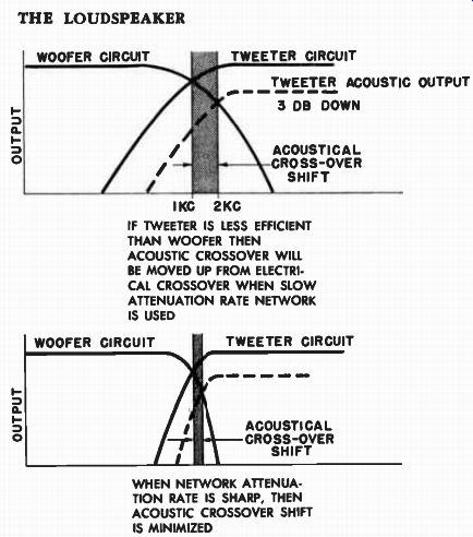
Fig. 7-21. Where speakers are not of equal efficiency, the actual acoustic
crossover point may be considerably different from the applied electrical
crossover. --------- WHEN NETWORK ATTENUAtion RATE IS SHARP, THEN ACOUSTIC
CROSSOVER SHIFT IS MINIMIZED IF TWEETER IS LESS EFFICIENT THAN WOOFER
THEN ACOUSTIC CROSSOVER WILL BE MOVED UP FROM ELECTRI CAL CROSSOVER
WHEN SLOW ATTENUATION RATE NETWORK IS USED WOOFER CIRCUIT TWEETER CIRCUIT
ACOUSTICAL CROSS-OVER SHIFT
Crossover Frequency Affected by Level Setting of Speakers
It will be realized that these shifts in crossover points may occur even for speakers of equal efficiencies if they are arranged with volume controls to vary their acoustic output. As soon as the level of output of the speaker is dropped, a change in acoustical output is produced, and the acoustic crossover moves around as the level is changed. Thus, for variable output networks, it may be desirable to use sharp rates of attenuation.
Crossover Frequency Affected by Level of Program Material
There is still another aspect of network performance that is beyond the control of the user, and that is the actual level of the program re corded or transmitted over the various bands. If the instruments of the orchestra are all playing at full loudness over the entire musical scale, the network-speaker-crossover combination obeys a general pattern similar to the crossover characteristic designed into the system. However, if only one portion of the original sound, say the middle frequencies, drops to pianissimo, the signal to the midrange speaker will drop, the acoustic output of that speaker will accordingly drop, and there will be a shift in the acoustical crossover.
Overall Crossover Characteristic Depends on Many Factors
It is for these reasons (commercial tolerances of components avail able for use in network, constantly varying speaker impedance, different efficiency levels of speakers, setting of volume controls, and signal distribution of the program) that the combined network-speaker performance may not be pinpointed microscopically. Inasmuch as it is impossible to take all these factors into account in the design of a network, the logical approach is to design the network to be electrically correct for the desired crossover points, at the attenuation rate desired, for the rated speaker impedance of the system, and to use commercially available components in its construction if the network is being built at home. If the ability to compensate for these changes in crossover points with frequencies or levels of speakers is desired, the constructor may use multi-impedance, multi-crossover adjustable networks.