Enclosures Provide Acoustical Crossover Characteristics
Crossover networks are vital components of multi-speaker systems.
They perform the important function of segregating specific bands of energy into specific channels. The electrical means of accomplishing this result were fully treated in Part I. In addition to electrical net works, there are mechanical networks that separate mechanical vibrations of different frequencies and channel them to the vibrating members best able to handle those bands. This was treated when we discussed two-way speakers with mechanical crossover elements. Then there is the matter of acoustical crossover networks, which play as important a part in the overall picture of frequency band segregation as do the electrical and mechanical elements.
In the discussion on multi-speaker systems, stress was placed on the compatibility of the component parts. To catalog them briefly: (a) the component speakers must be of equal efficiency for overall uniformity of level; (b) their ranges of operation should overlap so that there will be no depressions of the response characteristic in the areas joining the adjacent bands of the speakers; and (c) there must be compatibility of the greater angular dispersion of the high frequencies from the tweeter, as the high frequency beam from the lower range speaker sharpens. This is essentially a problem of acoustical crossover for the treble and tweeter units, and the reader may refer back to that section for a review of the question of compatibility in general. Our present concern is specifically with the action of woofer enclosures as part of the acoustic network of the system. Ae we examine them we find that they play as important a part in the function of the crossover characteristics of the system as do the smaller treble horns previously discussed.
Bass Reflex Channels Lows Only Through Port
Acoustical crossover principles are not specifically limited to multi speaker systems. In fact, a single speaker in a simple bass-reflex en closure is subject to the inexorable laws of acoustic crossover whether we like or not. Let us once again look at the bass-reflex enclosure, but this time a little more critically and just a bit more technically. We have said that the bass-reflex enclosure is a resonant acoustic device, being made up of an acoustic capacitance and an acoustic inductance, usually referred to as an inertance. There is an easy way of illustrating this combination if we wish to use electrical symbols; it is shown in Fig. 13-1. The section shown within the dotted square represents the bass-reflex enclosure. The electrical symbol of the capacitor is representative of the volume (capacity) of the enclosure. The electrical symbol of the coil is representative of the inertance of the air in the port of the enclosure, and the electrical symbol of resistance represents the radiation resistance of the air load that the port sees.
We will assume the speaker to be a generator of electrical signals of all frequencies that are to be transmitted through the enclosure network connected to it. We know that a choke coil will pass low frequencies and block high frequencies; that is, its reactance goes up with frequency. Thus, when the generator (loudspeaker) is producing low frequency signals, these signals will pass through the choke (the port) into the resistive load (radiation resistance of port), and power will be developed in the resistance. Transposing this statement into acoustic terms, we can say that when the loudspeaker is reproducing low notes, these notes will come out of the port and into the acoustic radiation resistance of the port, and low frequency power will flow out through the port.
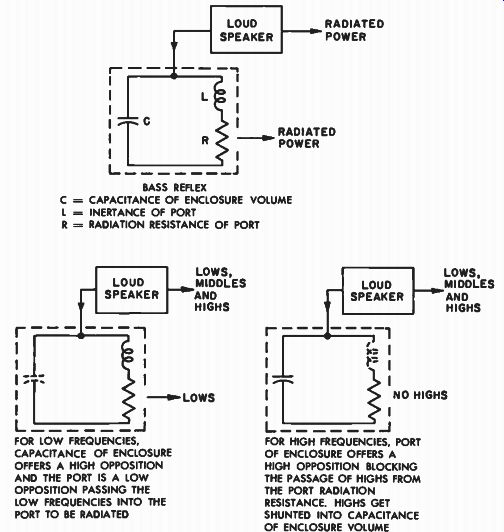
Fig. 13-1. The capacitance of the bass-reflex enclosure and the inertance
of its port act as L-C elements of a crossover network, allowing lows
from the port and restricting middles and highs to the speaker.
BASS REFLEX C -= CAPACITANCE OF ENCLOSURE VOLUME L = INERTANCE OF PORT R = RADIATION RESISTANCE OF PORT; FOR LOW FREQUENCIES, CAPACITANCE OF ENCLOSURE OFFERS A HIGH OPPOSITION AND THE PORT IS A LOW OPPOSITION PASSING THE LOW FREQUENCIES INTO THE PORT TO BE RADIATED FOR HIGH FREQUENCIES, PORT OF ENCLOSURE OFFERS A HIGH OPPOSITION BLOCKING THE PASSAGE OF HIGHS FROM THE PORT RADIATION RESISTANCE. HIGHS GET SHUNTED INTO CAPACITANCE OF ENCLOSURE VOLUME.
Port "Closes up" as Frequency Goes Up
Now let us return to the generator. If we raise the frequency of the signal being generated, the choke will begin to offer more and more opposition to the passage of the signals of increasing frequency, and fewer will get to the resistance. At the same time, however, the capacitor will begin to offer less opposition to those same signals. The higher frequency currents will thus begin to flow through the capacitor as they cease to flow in the other branch of the network. Again, translating this statement into acoustic terms, we can say that as the frequency of reproduction of the loudspeaker goes up, the port "closes up" acoustically, and those higher frequencies find their way into the acoustic capacitance volume of the chamber, instead of into a useful radiation resistance. As these higher frequencies enter the capacitance, no acoustic work is produced. Instead, as we have seen, these higher frequencies bounce back and forth from wall to wall within the cavity unless proper soundproofing is applied to the interior walls. Hence, the bass-reflex enclosure acts as a true crossover element, working entirely on acoustic principles. At low frequencies, it transmits sound from the port and there is both forward and rear transmission of power from the loudspeaker to the outside. At higher frequencies, the box closes up acoustically, and only direct forward radiation takes place from the diaphragm.
A Small Enclosure Provides Low Frequency Roll-off For Midrange Cone
This effect of the bass-reflex enclosure is, of course, not unique among enclosures. In fact, definite use is made of the simpler box enclosure and its crossover characteristic in the design of multi-speaker systems using cone speakers as midrange units. We have seen that as we decrease the size of the enclosure, the resonance frequency of the system increases. A small tight volume in back of a speaker acts like a tight air spring, preventing the speaker from vibrating as freely at low frequencies as it would in a larger enclosure. This enforced rise in resonance of the speaker, due to the smaller enclosure, has two effects. It raises the area of most efficiency of the system to a higher frequency, where it will be more useful, since this is to be strictly a midrange system. (See Fig. 13-2.) Secondly, the output falls off more rapidly below the new higher resonance point that results from the tightened enclosure. This transposition of the resonance point of high efficiency from some normally low frequency to a higher frequency within the midrange is, of course, very desirable. Just as desirable is the enforced cutoff of response below the new resonant frequency, for this may now be used as an acoustic component of the electrical cross over network whose job it will be to limit the low end response of the midrange speaker. Thus, in addition to boosting the midrange efficiency, the addition of a small closed box as a baffle for the mid range system affects the attenuation rate at the crossover point. Consequently, the final crossover characteristic may be made sharper than that obtainable from the electrical network alone.
Midrange Cone Enclosure Isolates it from Woofer Enclosure Pressures
The rear enclosure of the midrange speaker serves another useful purpose. It isolates the midrange cone speaker and prevents it from being affected acoustically by the woofer speaker. If the back of the midrange cone speaker were left open, the strong internal pressure developed within the main enclosure by the large excursions of the woofer diaphragm would tend to put the midrange diaphragm into sympathetic vibration with the woofer itself. This would result in cross-modulation of the midrange speaker by the woofer. The heavy low frequency pressures within the cabinet would tend to bounce the midrange diaphragm around. Boxing the midrange speaker removes these back low frequency pulsating forces from its diaphragm, leaving it free to perform the function for which it was installed. This condition of cross-modulation of the smaller by the larger speaker is not ...
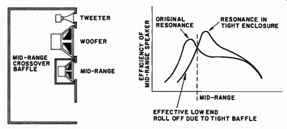
Fig. 13-2. Tight midrange speaker enclosure boosts high efficiency resonance
range of speaker into desired midrange band, and rolls off the low end
of the speaker. The tight box thus prevents the midrange speaker from
producing lows in the same manner as an inductive element of an L-C crossover
network. TWEETER WOOFER MID-RANGE ORIGINAL RESONANCE; RESONANCE IN TIGHT
ENCLOSURE MID-RANGE EFFECTIVE LOW END ROLL OFF DUE TO TIGHT BAFFLE
... so important when looked at from the front, because on this side, where there is free unconstrained radiation of the pressure, the pressures are not as intense as they are in the back of the cabinet, where they are confined into a relatively small space. Thus, the small midrange enclosure acts as an acoustical crossover element, and works hand in hand with the electrical network to produce the desired end result.
The Horn is a High-Pass Filter
Perhaps the type of enclosure in which acoustical crossover comes most into play is the horn. The important crossover factor in the horn is, of course, its own theoretical cutoff frequency. We have seen that the choice of the proper place to crossover electrically, in the case of a two-way system employing a horn for the upper range, is determined in part by the frequency at which the horn cuts off. Above that point (theoretically), the horn, operating essentially as a high-pass filter, passes all frequencies. This, in practice, however, is not necessarily true of the horn and driver unit combination. Even though the driver unit itself may have perfect response and the horn may be a perfect ...
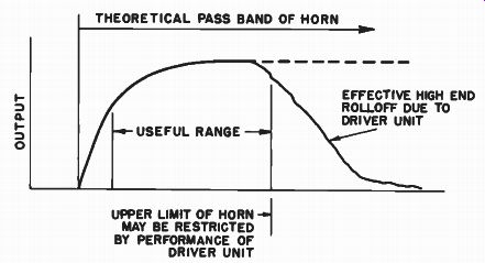
THEORETICAL PASS BAND OF HORN;
UPPER LIMIT OF HORN MAY BE RESTRICTED BY PERFORMANCE OF DRIVER UNIT
--- USEFUL RANGE--- EFFECTIVE HIGH END ROLLOFF DUE TO DRIVER UNIT
Fig. 13-3. In addition to its natural low frequency cut which acts as an acoustic crossover characteristic, the upper limit of the horn will be deter mined by the driver unit feeding it.
...horn, in combination an acoustical phenomenon may take place that could make it necessary to consider another crossover point within the pass band of the horn in addition to that determined by the cutoff point, as suggested in Fig. 13-3.
In this treatment, we shall deal first with the woofer horn and then discuss the same problem briefly in connection with the higher frequency horns. Figure 13-4 illustrates the typical construction of the compression chamber and the throat area of the woofer horn, with the throat diameter smaller than the diaphragm area, as is normally the case. We are now to examine the way the sound progresses from the diaphragm to the throat area. For the sake of clarity of exposition, the diaphragm has been shown to be flat. It is assumed, of course, that the diaphragm is one rigid piston, and that it moves as a whole. This means that all parts of the diaphragm move forward simultaneously by the same amount, and that they all move backward together by the same amount. We are going to consider what happens to the sound coming from the front of the diaphragm into the acoustic chamber between it and the throat of the horn.
Upper Band Pass of Horn Controlled by Driver Unit Head Design
Since all parts of the diaphragm are moving in synchronism, the sound coming from the diaphragm will constitute a flat or plane wave front. This may be considered as equivalent to saying that every section of the diaphragm is producing its own ray of sound. As these rays all move out together, they form a flat wavefront, as would a line of soldiers in company front formation. Now, if this flat wavefront had nothing to do but travel forward unimpeded, there would be no problem. However, in order to get into the throat of the horn, those rays coming from outer sections of the diaphragm will have to be bent from their line of march. They will consequently arrive at the throat of the horn at some later time than those rays coming directly from the center of the diaphragm. Acoustically speaking, there will be a phase delay between the center sound rays and the outer sound rays as they reach the throat.
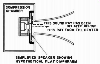
Fig. 13-4. Due to unequal path lengths from the different parts of the
diaphragm to the throat, these rays may arrive out of phase at the throat,
causing cancellation of sound. THIS SOUND RAY HAS BEEN DELAYED BEHIND
THIS RAY FROM THE CENTER SIMPLIFIED SPEAKER SHOWING HYPOTHETICAL FLAT
DIAPHRAGM
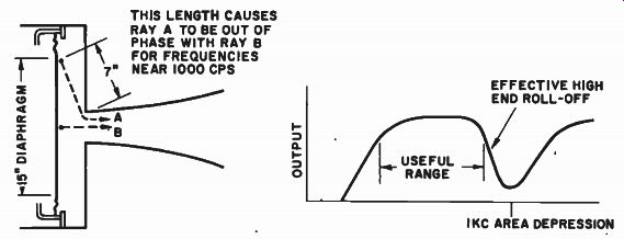
Fig. 13-5. Cancellation of energy at the throat due to path length differences
makes it necessary to cross over below area of cancellation. THIS LENGTH
CAUSES RAY A TO BE OUT OF PHASE WITH RAY B FOR FREQUENCIES NEAR 1000 HZ;
EFFECTIVE HIGH ENO ROLL-OFF IKC AREA DEPRESSION
If this difference in path length becomes large enough so that the longer paths are actually as much as a half wavelength of a particular sound to be produced, the delayed rays and the center rays will be completely out-of-phase at the throat, and severe cancellation for that frequency will occur at the throat. Consequently, for this frequency, there will be no sound transmission through the horn.
The response of the horn for the lower frequencies will not be so affected because these frequencies are of such long wavelength, and the path lengths in the chamber are so small compared to the long wavelengths of the low frequencies, that internal phase cancellation does not take place. Cancellation will take place for those wavelengths for which the path lengths from the center of the diaphragm and the outer areas differ by a half wavelength. As shown in Fig. 13-5, if the path length from the outer effective section of the diaphragm to the central part of the throat is 7 inches (as with a 15-inch speaker), this represents a half wavelength at approximately 1000 hz. There fore, with the throat size shown, and for the large speaker, the combination of horn and driver unit will fall off sharply at this critical frequency.
This characteristic of driver-horn combinations may be readily corrected at the driver unit. It will be found that in driver units made for high frequency operation, the heads are designed with phase correcting plugs or devices that help to equalize the various path lengths from all parts of the diaphragm to the throat, so that this destructive internal cancellation does not take place within the desired operating range of the horn. Such phase correcting units are shown in Fig. 3-14.
In the case of the folded woofer horn, however, it would obviously be of no practical value to employ such high frequency correcting devices. Therefore, we allow this higher frequency deterioration to take place and employ it as a natural acoustic crossover effect of the horn, when the horn is employed as a woofer. In this sense, then, the woofer horn combination is a bandpass filter rather than just a high-pass filter, as illustrated in Fig. 13-6. It passes frequencies above that of the theoretical cutoff point of the horn, and below the frequencies at which destructive throat air chamber cancellation takes place.
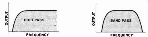
Fig. 13-6. Horn is changed from high-pass element to band-pass element
by allowing throat cancellation to take place. This is permissible where
horn is applied to woofer. Horn thus acts as high end rolloff filter for
woofer section.
Chamber Between Diaphragm and Throat is a Low-Pass Filter
There is another acoustical crossover characteristic of the throat chamber of the horn, where only the back of the speaker is horn loaded and the front of the speaker radiates directly. In this structure, shown in Fig. 8-3 (A), there is a low-pass acoustic filter between the rear of the diaphragm and the throat of the horn. This cavity represents a capacitance across the line, as illustrated in Fig. 13-7. The narrow throat represents an inductance in series with the line. That is, the sound from the back of the diaphragm can disperse in this cavity but, at the same time, must get through the throat of the horn to be radiated.
This is essentially an acoustical counterpart of the familiar electrical low-pass filter. Highs are shunted out of the line by the capacitor.
Accordingly, those lower frequencies within the band, which are not materially affected by the cavity capacitance, will be passed on by the acoustic filter and will get into the horn to be radiated as sound power, provided the theoretical cutoff of the horn itself is such as to allow them to pass.
This air chamber, by preventing the passage of middles and highs into the horn, becomes a "storage chamber" for these frequencies. The middles and high frequencies from the back of the cone will, there fore, see an acoustically "stiffer" enclosure at their back, due to this filter imposed between the cone and the throat. Consequently, those upper frequencies which are front radiated will now issue from an enclosure that has been tightened up, and as a result there will be some what better rear-loading of the speaker for these higher frequencies.
Better middle and high frequency efficiency will be obtained. For the lower frequencies, the rear enclosure chamber "opens up," due to the low-pass characteristic of the filter, and the proper rear loading of the horn to the speaker takes place for the low frequencies.
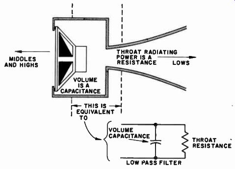
Fig. 13-7. In compound horn, rear volume is a low-pass element. It "stores" highs
and middles, stiffening the rear of the speaker for these frequencies
and improving the middle and high frequency loading of the diaphragm for
forward radiation. Acoustic crossover action is thus accomplished by the
enclosure.
Horn Bends are Low-Pass Filters
There is another acoustical crossover phenomenon that takes place in folded horns, and this is brought about by the necessity for the sound wave to travel around the bends of the horn. Destructive cancellation of high frequencies may take place because of the difference in the path lengths that sound rays have to travel in negotiating a corner. Secondly, a loss of high frequencies will also occur because of the greater difficulty that high frequency waves experience in diffracting around corners. These two effects are not necessarily the same.
Taking first the more familiar effect, that of diffraction, we know that diffraction of a sound wave is accomplished much more easily for those frequencies at which the wavelength is large compared with the opening from which they emerge. Thus, as shown in Fig. 13-8, if the wavelength of the sound is such that the pulse leaves the opening of the duct before the succeeding pulse has been thoroughly established behind it, this first pulse is free to expand in all directions once it is out in the open. It will, therefore, spread out in all directions, and "diffract" around the sides of the duct. However, in the case of frequencies at which the sound pulses are literally on top of one another as they emerge from the duct, one pulse will keep urging the one in front of it in the direction in which it started - straight ahead. There fore, there will be less diffraction of the higher frequencies from this same duct. If this duct happens to be the end of one section of a folded horn, the higher frequencies will not get around the bend as easily as the lower frequencies. The bent horn, therefore, presents an acoustic high frequency filtering action; that is, it acts as a crossover element in the total acoustic circuit. In addition to the above effect, multiple reflections of the higher frequency sounds occur at the bend. This causes some of the energy to be bounced back toward the speaker and to be scattered in directions that may not contribute toward getting the high frequency sound waves around the bend.
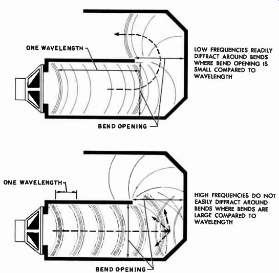
Fig. 13-8. High frequency attenuation will occur in a folded horn due
to poor diffraction around bends, unless horn is specifically designed
for high frequency radiation. (See Part 1, Fig. 3-20.) ------ ONE WAVELENGTH
BEND OPENING LOW FREQUENCIES READILY DIFFRACT AROUND BENDS WHERE BEND
OPENING IS SMALL COMPARED TO WAVELENGTH HIGH FREQUENCIES DO NOT EASILY
DIFFRACT AROUND BENDS WHERE BENDS ARE LARGE COMPARED TO WAVELENGTH
Figure 13-9 illustrates the further cancellation of high frequencies that actually do manage to get around a bend. If the bend is quite large in cross-section compared to the radius of the bend, the path lengths close to the inner wall will be much shorter than the path lengths close to the outer walls, as can easily be seen from the figure.
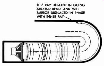
THIS RAY DELAYED IN GOING AROUND BEND, AND WILL EMERGE DISPLACED IN PHASE
WITH INNER RAY
Fig. 13-9. Where bend cross-section is large, there will occur phase displacement of the rays from different areas of the bend resulting in eventual cancellation of high frequencies where these phase shifts amount to 180°. In bent woofer horns this constitutes an effective high frequency rolloff characteristic.
This means that, if the wavefront for a particular high frequency started out straight at the beginning of the bend, by the time it got around to the end of the bend, a good part of it would be delayed. As the bends continue to occur, or as their sharpness increases, parts of this advancing wavefront of the high frequencies become more and more delayed until soon half of it is out of phase with the other half.
The end result is a sharp drop in acoustic output for the higher frequencies from the folded woofer horn. This deterioration of the high frequencies may be minimized in folded or reflexed horns where it is desired to operate them in their high frequency region. In such a reflexed horn, as shown in Fig. 3-20, the expansion of the horn is accomplished so that the width of the horn at the bends is very small compared to the radius of the bends, and very little high frequency attenuation occurs. Thus it is seen that the folded woofer horn be comes an element in the crossover system by attenuating the higher frequencies through the combined effect of poor diffraction around the bends of the horn and the increasing phase differences in the wave front of the high frequencies passing around the bends of the horn.
It will be recognized that almost the same set of conditions of bending and diffraction exists in the acoustic labyrinth, causing the acoustic labyrinth to serve the same acoustical crossover function.
There is one difference between the two enclosures, however. In the folded horn, only the horn itself has a low frequency cutoff and it will pass all frequencies above that point that reach its throat in fairly uniform phase. In the case of the labyrinth, however, the rear duct is tuned to one particular low frequency, and above that frequency its radiation drops off at a gradual, steady rate. Therefore, the low-pass filter at the back of the diaphragm in the labyrinth, in conjunction with the labyrinth itself, usually cuts off at a considerably lower frequency than the filter for the folded horn, since the horn extends out further in its transmission band.
Final Crossover Characteristic is Function of Electrical, Mechanical, Acoustical Elements
Although many of the factors discussed in this sectionare often beyond the control of the home constructor, it is still of value to realize that they exist in baffles and enclosures, just as they exist in the speakers themselves (over which he likewise has no control). The value of being cognizant of these phenomena, however, lies in the realization that one is dealing with a system of components whose performance is a function of the teamwork between all the components throughout the entire electrical-mechanical-acoustical circuit. It is not correct to state categorically that because the electrical network someone happens to buy or make is a 6- or 12-db per octave type, his system is going to operate at that rate of attenuation. The final performance will be almost equally tempered by the response characteristic of the speaker units used and the crossover effects of the auxiliary acoustic enclosures in which the loudspeakers are to be installed.