1-1. Introduction
Electric meters are devices which measure electric current and other electrical quantities and indicate the quantity measured. The heart of an electric meter is the meter movement. The movement translates electrical energy into mechanical energy which causes visual indication. The indicator usually is a pointer moving across a calibrated scale.
A number of different types of meter movements have been designed and are in use. The most important of these is the moving-coil movement, which in its original form was developed by the French scientist D'Arsonval. The modern moving-coil movement is the result of the work of Dr. Edward Weston, who considerably improved on D'Arsonval's original version. In its present-day form moving-coil movement is referred to as either a Weston-type or a D'Arsonval movement. A majority of the meters discussed in this guide use this type of mechanism.
1-2. Principles of the Moving-Coil Meter Movement
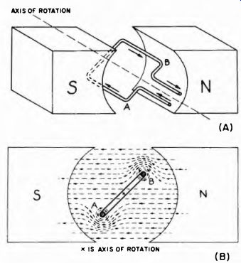
Fig. 1-1. Illustration of the basic motor principle employed in moving-coil
permanent-magnet meters.
This type of meter depends for its operation on the reaction between a direct current-carrying coil and a stationary magnetic field.
The magnetic lines of force generated by the current in the wire interact with the unvarying lines of force of the magnetic field in which the coil is located, and the coil is forced to move with respect to the stationary field. By virtue of its physical design, the coil rotates. In order that there be useful interaction, the current in the coil must be unidirectional, hence the instrument is a d-c meter.
Suppose a loop of wire is located in a magnetic field (Fig. 1-1 A) in which the poles of the magnet are concave, so that the loop of wire can revolve freely. Direct current is made to flow through the coil.
The result is shown at (B) of Fig. 1-1, where the cross sectional view indicates the magnetic lines of force. Note that the lines of force from the magnet and wire are in the same direction above, wire B, so wire B is forced downward. They also run in the same direction below wire A, so wire A is forced upward. By making the coil of many turns the effect is increased, and the same rotational force (torque) can be obtained with a smaller current in the coil.
1-3. D'Arsonval Moving-Coil Mechanism
The construction of the moving-coil meter mechanism is shown in Fig. 1-2. The permanent magnet which provides the stationary field is equipped with extensions, called "pole pieces," shaped to fit around the moving-coil assembly. The moving coil is wound on a thin, light, non-magnetic metal form attached to pivots which rotate on jeweled bearings. Helical springs are attached to the ends of the coil and are also used to carry current from the external source to the moving coil. An iron core is mounted inside the coil so that the magnetic path from the main horseshoe, permanent magnet is entirely through iron, except for the annular gap in which the thin sides of the moving coil rotate. The pointer is mounted on the moving-coil assembly so that it moves with the moving coil. Mechanical stops are mounted on the meter to limit the movement of the pointer to its desired range.
[ 1. The direction of lines of force around the wire can be determined from the "left hand rule'' which says that if the wire is grasped in the left hand with the thumb extended along the wire in the direction of electron flow, the fingers will point around the wire in the direction of the magnetic lines of force.]
When a current is passed through the coil, interaction between the magnetic fields of the coil and magnet rotates the moving-coil assembly clockwise against the resistance of the springs. When the force of resistance from the springs becomes equal to the force of rotation from the action of the magnetic fields, the moving coil and the attached pointer stop. How far the pointer will move to the right depends upon the amount of current in the coil. By using a scale across which the upper end of the pointer can move, we can read how much current is flowing through the coil. The scale is calibrated; that is, each meter is designed to measure certain values of current; these are marked on the scale. How a scale is added to the mechanism is indicated in Fig. 1-3. The indicating pointer is attached to the coil assembly, and swings with it. There is a screw on the front of the movement to permit adjusting the pointer to its mechanical zero for zero current. (See Fig. 12(D).)
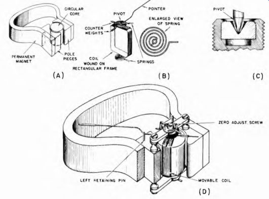
Fig. 1-2. Details of construction of the Weston type moving-coil mechanism.
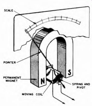
Fig. 1-3. How a scale is added to the basic mechanism.
1-4. Coil Resistance
We noted in Sec. 1-2 that an increase in the number of turns in the coil reduces the amount of current necessary to produce a given turning force, and thus deflection, of the pointer. Accordingly, meters designed for the lowest full-scale deflection current must have the greatest number of turns of wire on the coil, and are referred to as the "most sensitive" meters. The lower the full-scale current rating of a meter, the greater is its sensitivity. But whatever the sensitivity rating, each moving-coil meter also bears its own d-c resistance rating.
Since sensitive meters require more turns of wire they also have the greatest coil resistance. The resistance of a meter is a very important thing to know for, as will be explained later, the resistance of a meter determines its usefulness in making practical current and voltage measurements in electronic circuits.
1-5. Scale Calibration for Moving-Coil Type Meter
The force tending to rotate the moving coil assembly is proportional to the coil current. At the same time, the resistance torque of the springs is directly proportional to the degrees of rotation from the zero position. These two facts lead to the conclusion that the displacement of the pointer along the meter scale is directly proportional to the current. When a relation of this type exists, we say that the scale is linear. A linear scale means that the same change in current always produces the same change in pointer position no matter in what part of the scale the pointer is when the change is made.
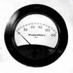
Fig. 1-4. The linear scale used with a typical moving coil meter.
Figure 1-4 shows a typical linear meter scale, 150 milliamperes d e full scale. Notice that this scale is labeled every 30 ma. There are five divisions for every 10 ma; each division representing 2 ma each. Now note that the separation along the scale from zero to 10 ma is the same as the distance from 30 to 40 ma, from 60 to 70 ma 80 to 90 ma 140 to 150 ma and between any two points 10 ma apart.
The linear scale is characteristic of the d-c moving-coil permanent magnet meter movement, as compared to other types, which employ non-linear scales. These non-linear types are shown in Section 2 and elsewhere in this guide.
1-6. Importance of Polarity
The steady magnetic field in which the moving coil operates is supplied by the permanent magnet. This field is constant and always in one direction. In other words the North pole remains North and the South pole remains South, For this reason, the current in the coil must always have the proper polarity, or flow in the proper direction to make the pointer deflect normally (from left to right) Therefore, for the instrument to give the desired indication, the polarity of the terminals of a moving coil (d-c) meter must be taken into account in making connections. On most instruments this polarity is indicated on the case near each terminal or on the terminal itself.
Frequently only the positive terminal is marked with a 4- sign; then, of course, the other terminal must be the negative one. The meter must be so connected that the electron flow is into the negative terminal and out ol the positive terminal.
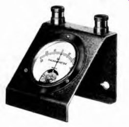
Fig. 1-5. A Weston center zero galvanometer.
The moving-coil permanent-magnet (d-c) meter cannot be used to measure alternating or rapidly varying direct currents and voltages without the use of auxiliary equipment, such as a rectifier. When alternating current is passed through the coil of the d-c meter the coil's magnetic field changes polarity with each new alternation of the current. The coil assembly and the pointer thus tend to rotate back and forth in synchronism with the current's alternations. Although at power frequencies as low as 25 hz some vibration of the pointer may be noticeable, at 60 hz and higher the inertia of the system prevents the pointer from moving at all.
1-7. Center-Zero Galvanometer
The term "galvanometer" has taken on a special meaning. It is used to distinguish a certain type of d-c meter having two main characteristics of the original D'Arsonval moving-coil instrument. These are great sensitivity, and zero-current indication at the center rather than at the left end of the scale.
In the galvanometer, the moving coil is suspended in such a way that it can move the pointer in either direction from its center position. It is used primarily in applications in which it is desired that a balance be indicated; in other words, applications in which normal current is zero, and deviation from zero in either the positive or the negative direction is to be observed. An example of this instrument is shown in Fig. 1-5.