The measurement of an alternating current (or voltage) is the measurement of a continuously varying quantity. The d-c moving-coil meter movement can make this measurement if the frequency of the current is very low, up to a few cycles per second. At these low frequencies the moving coil can follow the changes in current value and direction instant by instant. However, if the frequency is higher, and most a-c meters are used at power frequencies which are between 50 and 60 hz, the moving-coil type of meter movement is not suitable for direct application and must be "adapted," as is described in Section 6. Hence a different type of meter movement is required.
2-1. Basic Principle of Moving-Iron Meters
If a soft iron bar is placed near a coil which is carrying current, the bar becomes magnetized, as illustrated in Fig. 2-1. The magnetic lines of force issuing from the coil pass through the bar in the same direction as the lines of force induced in the bar by the coil. Since lines of force behave like stretched rubber bands that try to shorten themselves as much as possible, the bar is attracted to the electromagnet.
If the coil is fixed and the bar is free to move, the bar is pulled into the coil.
If the current in the coil reverses, the lines of force issuing from the coil reverse, and the lines of force in the bar also reverse. The lines of force in the bar line up with the lines of force coming from the coil, and the bar is again attracted to the coil. Therefore the soft iron bar is attracted to the electromagnet regardless of the direction of the current flowing in the coil, hence the magnetized bar is attracted to the coil with de or ac flowing in the coil. Soft iron is used for the bar because it demagnetizes readily when the current through the coil ceases.
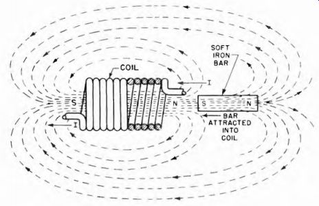
Fig. 2-1. Basic principle behind the action of the moving-iron type of meter.
When the coil illustrated in Fig. 2-1 carries the sine waveform current shown in Fig. 2-2, the direction of movement of the bar into the coil is the same during each half cycle or alternation. This is true in spite of the fact that the current reverses its direction of flow. The extent of the motion of the magnetized bar depends on how freely it can move and on the amount of current flowing in the coil, hence the intensity of the magnetizing force.
The fact that there is a repulsion between the induced field in a metal object and the alternating field inducing it is the basis of operation of a group of a-c meters. They are known as the moving-iron type of meter.
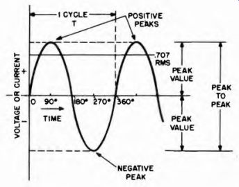
Fig. 2-2. Basic sine wave, showing how the current or/voltage builds up in
one direction, returns to zero and then builds up in the other direction, finally
returning to zero at the end of a complete cycle.
2-2. Moving-Iron Types of A-C Meters
These meters make use of the principle that a coil carrying current magnetizes a piece of soft iron which is placed within the coil's magnetic field. In practical devices two pieces of iron are used instead of one, and both are placed under the influence of the same magnetic field by being located within the coil. The principle is shown in Fig. 2-3.
When current flows through the coil the two bars are magnetized with the same polarity. Because these adjacent poles are of similar polarity, they repel each other. If the current reverses, as in Fig. 2-2, the polarity of both magnetized rods is reversed at the same time and they still repel each other. If one bar is fixed and the other is free to move, the force of repulsion can be made to indicate the amount of current flow by causing the movable bar to move a pointer across a calibrated scale.
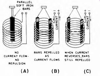
Fig. 2-3. Illustration of the basic principle underlying the operation of
the moving-vane meter. The electromagnet magnetizes both bars with the same
polarity, so they repel each other with a force depending upon the strength
of the current in the coil. parallel NO BARS REPELLED CURRENT FLOW- AS NO CURRENT
FLOWS REPULSION WHEN CURRENT REVERSES,BARS STILL REPELLED (A) (B) (C)
Now an interesting fact about meters which use the principle of repulsion between two magnetized pieces of iron is that the repulsive force varies as the square of the current rather than directly as the current through the coil. Because both bars are magnetized, each contributes to the force which moves the movable bar. If a unit value of current through the magnetizing coil displaces the movable bar .04 inch from the stationary bar, doubling the current in the magnetizing coil will increase the separation between the two bars four fold, or separate them 0.04 x 4 or 0.16 inch. If the current is tripled the separation increases nine-fold, always changing as the square of the current change.
The above figures of physical displacement are purely illustrative and serve only to correlate the measurement of a varying quantity, such as the sine waveform a-c voltage in Fig. 2-2, with the behavior of the measuring device.
In any application of alternating currents it is useful to express both currents and voltages in terms of their root-mean-square (rms) values. Rms values are important because they are the only ones connected with a-c quantities which will give correct answers when used in the power formula P - PR. Thus, unless there is a special reason for doing otherwise, alternating currents and voltages are always expressed in rms values. The rms value is derived by taking the square root of the average of the squares of all the instantaneous values included in a half-cycle, or any number of complete half-cycles. For the commonly encountered sine wave, the rms value is simply 0.707 times the peak value (see Fig. 2-2). For waves of other forms the rms value has a different relation to peak or average value.
Referring again to the sine waveform curve shown in Fig. 2-2, the fixed relationship between the peak and the rms values make it possible to convert any rms value to a corresponding peak value, and since the positive and negative peaks of a sine waveform are alike in amplitude, differing only in polarity, the maximum amplitude limits of an alternating current (or voltage) are expressed as the peak-to-peak value. Hence any a-c meter which is calibrated in rms values can state the corresponding peak-to-peak values on the same scale. Such multiple calibration is found on some meters, although not too frequently.
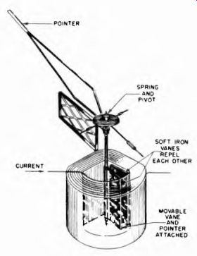
Fig. 2-4. Details of construction of the radial-vane type of moving iron meter.
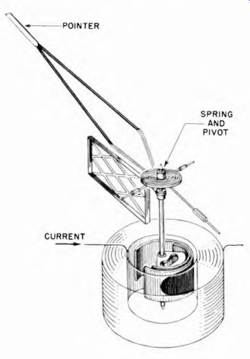
Fig. 2-5. Details of construction of the concentric-vane type of moving-iron
meter.
Because of the square relation between the displacement and current, explained above, the displacement of the moving iron in this type of meter is directly proportional to the rms value of the current being measured. Thus this type of meter can read a-c and d-c values on the same scale and is not sensitive to waveform.
The basic principle described in Fig. 2-3 is applied in two groups of a-c meters, the radial vane type and the concentric vane type.
2-3. The Radial and the Concentric Vane Meters
In the radial type, two rectangular vanes are placed inside the coil as illustrated in Fig. 2-4. One vane is fixed and the other is free to rotate on pivots. The movable vane has a pointer attached. When current goes through the coil, the iron vanes become magnetized and repel each other. The movable vane swings away, carrying the pointer across the scale, thus indicating the amount of current flowing through the coil.
In the concentric vane type shown in Fig. 2-5, the soft iron vanes are semicircular, with one inside the other. When the current flow's through the coil, lines of force pass through both vanes. The movable vane swings away from the stationary one and moves the pointer across the scale. The amount of swing depends upon the strength of the current in the coil and the control action of the springs.
2-4. Scale Calibration in Moving-Vane Meters
Section 1 explained how the moving-coil permanent magnet d e meter employs a linear scale, in which a given difference in current is represented by a fixed distance along any part of the scale (Sec 1-5)
Moving-vane meters, however, have non-linear scales. The numbers in the lower portion of the scale are crowded together, while those at the high end are spread further apart. This type of scale is illustrated in Fig. 2-6. It is known as the square-law scale and is the type which results ...
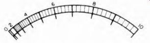
Fig. 2-6. Non-linear, "square
law" meter scale.
... whenever the measured current operates through two agencies at the same time. Each magnetized vane is an agency. If a given measured current through the meter is doubled, each vane is magnetized twice as strongly. Since each vane then repels the other twice as much, the combined repulsion between the two vanes is lour times as great. In other words, the force of repulsion and the pointer swing do not vary directly with the current but vary as the square of the current.
2-5. The Hot-Wire Current Meter
This meter uses the physical effects of heat generated by current flow in a wire. The physical change (thermal expansion) in the wire moves a pointer which registers the current in the circuit. Figure 2-7 shows the arrangement. The meter is connected in series with the load by means of terminals A and B. Inside the meter, wire 1 carries the current. Wire 2 is attached to the current carrying wire near the center and pulls on it with a tension controlled by a spring. Wire 2 passes along the round base of a pivoted indicating needle and is used as a drive wire to move the needle. When current passes through wire 1 the wire heats up proportionally to the square of the strength of the current. The higher the current the greater the amount ol heat generated, and the more wire 1 expands. As it expands, the drive wire 2 is pulled down by the tension of the spring. Wire 2, riding along the base of the pivoted needle, drives the pointer across the scale. The pointer is adjusted to read zero with zero current by means of a screw regulating the normal sag in wire 1.
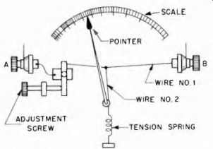
Fig. 2-7 Organization of component parts in "hot wire" ammeter.
The hot-wire meter is suitable for use not only at power-frequencies but is also useful at radio frequencies. While the hot-wire type is still in use to some extent, the development of thermocouple devices has greatly reduced its application. The relationship between the current and the force developed in the meter to move the pointer is in accordance with the square law, hence the scale used resembles that shown in Fig. 2-6.
The weaknesses of this type of instrument are numerous and have been responsible for its replacement by other types of equipment. The zero setting is indefinite and requires frequent readjustment, it is slow acting and it requires the consumption of an appreciable amount of energy in order to cause the generation of sufficient heat, hence it is not as sensitive as other types.
2-6. The Electrodynamometer
The action of a movable coil carrying current in a fixed magnetic field supplied by a permanent magnet was discussed in Section 1. (Sec. 1-2, Fig. 1-1.) The action is similar if the permanent magnet is replaced with another coil carrying current. The electromagnet then supplies the fixed field against which the magnetic field of the moving coil acts while rotating to indicate current intensity.
The principle of the electrodynamometer (sometimes shortened to ''dynamometer ') is illustrated in Fig. 2-8. The schematic symbols of the coils are shown in approximately their operating positions. The turns of the fixed coils are distributed equally on both sides of the movable coil. When current flows through the coils, the polarity of the magnetic fields is such that the movable coil rotates to align itself with the fixed coils. If the current through the coils is reversed the magnetic polarity of both the movable and the fixed coils is reversed.
The relative polarities are still the same, so the motion is still the same as before. For this reason the electrodynamometer is suitable for the measurement of both direct and alternating currents. It is not useful ...
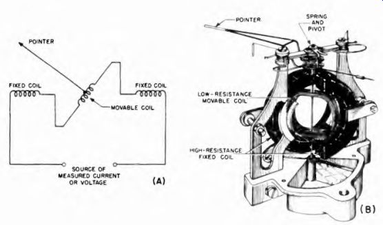
Fig. 2-8. (A) Schematic diagram showing the principle of the electro-dynamometer.
The magnetic fields of the fixed and movable coils interact to cause the latter
to rotate.
Fig. 2-8. (B) Constructional details of a dynamometer type instrument, with schematic diagram.
... for alternating current of higher than power frequencies because of the mass of the moving parts.
The deflecting force in this type of meter is derived from the current in two ways at the same time; the current acts through the field it creates around the movable coil and again through the field it creates around the fixed coil. For this reason, the scale of this meter follows the square law and is like that shown in Fig. 2 6. The electronic technician and experimenter is most interested in the dynamometer because of its use as a wattmeter, which is explained in Section 4.
2-7. Thermocouple Meters
These meters function by virtue of a difference of potential generated at a junction of two dissimilar metals when current flows through the "heater" element. The voltage so generated is applied across the coil terminals of a moving-coil permanent magnet meter. It is described in detail in Section 6.