11-1. Oscillators
A diagram of a typical electron-coupled oscillator used in an a m transmitter is shown in Fig. 11-1 (A). Normal measurements are grid current with a low-range d-c milliammeter, and screen and plate currents with ranges suited to the tube and operating conditions. Meter 1 is frequently a permanent part of the transmitter circuit, since it is used m tuning the plate circuit to resonance. When the adjustment of capacitor C brings the tuned circuit near resonance, the plate current dips and becomes minimum at the resonant point. Voltage measurements are shown by the dotted lines.
Figure 111(B) shows the circuit of a crystal oscillator. Similar measurements are made here, sometimes with the addition of an r-f meter connected in series with the crystal to check the r-f current through it. Since excessive r-f current through the crystal can cause damage, measuring keeps a check on it. Voltage measurements are shown by the dotted lines.
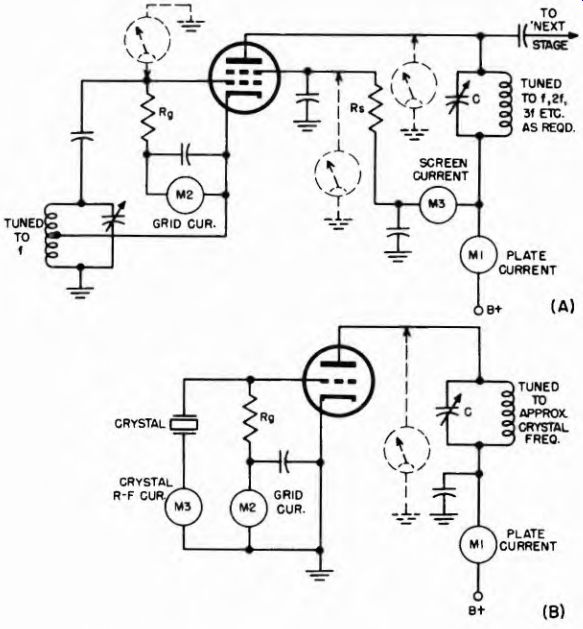
Fig. 11-(A) Electron-coupled oscillator circuit, such as controlling circuit
of transmitters, and locations of Fig. 11-(B) Crystal oscillator circuit and
meter is used for the frequency typical meter measurements, measuring locations.
11-2. R-F Amplifiers in Transmitters
Figure 11-2 shows a class C amplifier used in radio transmitter r-f sections. As Oscillators do, class C amplifiers draw grid current. There fore, meters must be used to measure the grid voltage or grid current.
Note that a meter is shown in the cathode lead The cathode current includes plate, screen, and grid currents, since they must all pass through the cathode in returning to the tube. The plate and screen voltages are often controlled by a switch; then, when the switch is off, the grid current alone registers on the cathode meter. However, it must be remembered that this grid current is somewhat higher than that which actually flows when the plate and screen voltages are applied.
As in previous cases, screen and plate currents are measured by series milliammeter connected as shown. Another meter indicates the combined screen and plate current.
The circuit of Fig. 11-2 is general, and also applies to buffers, frequency multipliers, and power amplifiers of the r-f sections of transmitters. The use of a triode, tetrode, or pentode determines the number of active tube electrodes, hence the number of circuits which are metered.
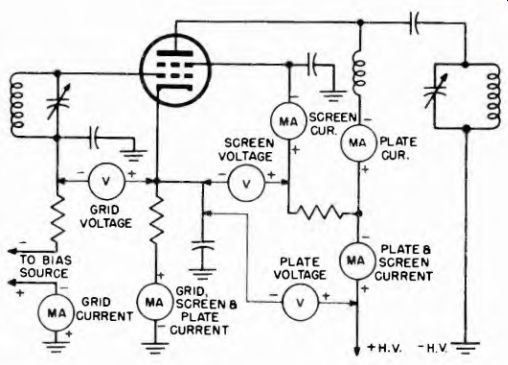
Fig. 11-2. Class C r-f power amplifier for transmitter, current and voltage
measurements.
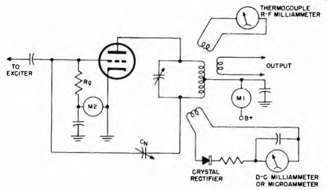
Fig. 11-3. Two methods of using meters to indicate r-f in the plate circuit
of a class C amplifier during neutralizing procedure.
11-3. Using Meters in Neutralizing Transmitters
Most triode r-f amplifiers, and some tetrode and pentode amplifiers, operated at very-high radio frequencies must be neutralized. This necessity arises from the fact that, without neutralization, the grid-plate interelectrode capacitance of the tube forms a path for positive feedback which causes the tube to oscillate, destroying its amplifier action. A neutralizing capacitor forms another path which feeds back energy in opposing phase to compensate.
Because of the variations in individual circuits, the neutralizing capacitance cannot be preset to the exact value necessary, but must be adjusted after the transmitter is constructed and being tested. Figure 11-3 shows a typical neutralized amplifier and two ways in which meters can be used as neutralization indicators.
The plate voltage is removed from the amplifier, but the exciter is left running, so that drive voltage is applied and grid current flows.
If the circuit is not completely neutralized, some of the grid-circuit signal feeds through the grid-plate capacitance to the plate tank circuit.
As Cx is tuned to the proper value, compensating grid signal is also fed through it to the plate tank. Thus, the capacitor CN is adjusted for minimum r-f current in the plate tank. To make this adjustment possible, some indication of the r-f current in the plate tank must be available.
One type of indicator is a loop of wire whose ends are connected to a thermocouple milliammeter as shown. The r-f energy is coupled into the wire loop when the latter is held close to the plate tank coil and registers on the meter.
Another indicator uses a d-c meter movement in series with a crystal-diode rectifier. The crystal rectifies the r-f and the rectified current actuates the d-c meter. In the case of either indicator, the capacitor Cs is adjusted for minimum meter reading, while the plate tank capacitor is readjusted for resonance each time.
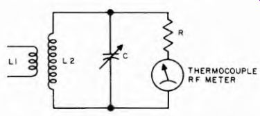
Figure 11-4
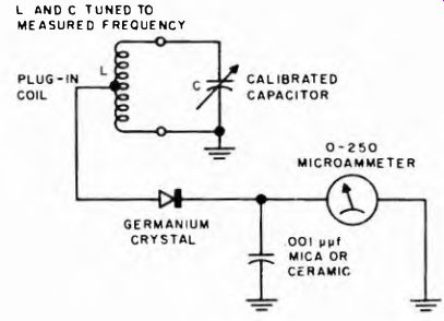
Fig. 11-5. Wavemeter using a microammeter and crystal diode to indicate resonance.
11-4. Measuring Transmitter Power Output
If the impedance of the antenna to which a transmitter is connected is accurately known, the r-f current into the antenna can be measured with a thermocouple ammeter and the square of the current multiplied by the antenna resistance to give the output power.
However, antenna impedance often is not known accurately, and transmitter capabilities are usually measured by loading the output stage with a dummy load, which is a load resistor designed to substitute for the desired impedance of the antenna. Devices used to measure transmitter power output are sometimes referred to as r-f wattmeters.
Perhaps the simplest r-f wattmeter is that illustrated in the diagram of Fig. 11-4. R-f energy is coupled from the tank circuit of the transmitter through L1 into L2. The variable capacitor C is tuned to resonance for maximum deflection of the thermocouple meter pointer. The power output then equals the square of the indicated r-f current times the resistance R. R must be a non-inductive resistor whose r-f resistance at the frequency of measurement is accurately known. It is also desirable that the value of R approximate the resistance of the antenna to be used.
11-5. Frequency Measurement with Wavemeter
Figure 11-5 shows how a d-c meter may be used with a crystal diode in a wavemeter to indicate resonance in making frequency measurements. The coil is coupled to the transmitter tank and the calibrated capacitor is adjusted until the meter reads a maximum. The calibration on the capacitor dial then indicates the frequency of the measured signal.
Wavemeters are usually of the plug-in type and are equipped with a number of coils which can be changed to cover a wide frequency range.
11-6. Modulation Percentage
Figure 11-6 shows an instrument suitable for measuring modulation percentage. L and C3 are tuned to the transmitter carrier frequency.
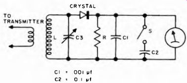
Fig. 11-6. Circuit suitable for measuring modulation percentage.
The crystal diode rectifies the r-f current so that a d-c voltage plus a-c modulation appears across R. C1 is a relatively small-value capacitor and filters out the rf. The d-c meter then responds to the average voltage.
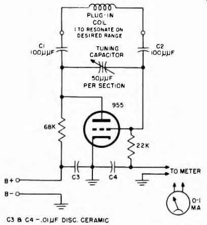
Fig. 11-7. Typical grid-dip meter circuit.
When S is closed the meter becomes peak-reading, and the d-c voltage indicated goes up to the peak value of modulation. The difference between the two readings compared to the d-c voltage (average value) is the percentage of modulation.
11-7. Grid-Dip Meter
One of the most useful instruments for design and testing of transmitters and receivers is the grid-dip meter. The circuit is shown in Fig. 11-7. It is simply a low power oscillator in which the grid current is measured by a sensitive microammeter. When the oscillator is loaded, such as by a nearby tuned circuit on the same frequency, the grid current is reduced. Thus, as the variable capacitor is adjusted so that the frequency of the oscillator passes through the resonant frequency of the circuit to which the coil is coupled, the grid current "dips." The dial connected to the variable capacitor is calibrated to read frequency. Thus, the resonant frequency of a circuit in a transmitter or receiver can be determined.
The applications of the grid-dip meter are numerous. Given the coils which afford the required frequency range, the device is a low powered test signal source where such signals are required; when a system is tuned to its frequency and coupling exists between that circuit and the grid-dip meter, the meter indication will decrease abruptly at resonance.