In this section we review the most important ways in which meters can be used, with emphasis on electronic circuits. First, however, let us compare the general features of each of the three main types of meters: the panel-type meter, the volt-ohm-milliammeter (VOM) and the VTVM so there will be no doubt as to which is most appropriate for each application.
GENERAL CONSIDERATIONS
10-1 Panel Instruments
Typical panel-type meters are illustrated in Fig. 10-1. The three types are designed to be mounted permanently in the equipment in which they are used. In most cases the meter movements are designed to operate best with the meter face in a vertical plane. A mechanical zero adjustment is provided as shown in the figure. This is used to adjust the pointer to a zero scale reading when no current is flowing. It should be adjusted with the meter positioned in the plane in which it will be used.
Parallax. The refractive quality of the glass face cover may lead to an effect called parallax, which makes the pointer appear to be in two places at the same time. Because this can lead to error, the meter should be read from directly in front, or directly down. Looking at the meter face at an angle will result in erroneous readings. Parallax is minimized in the more expensive varieties by using a knife-edge pointer riding across a strip of mirror which reflects the pointer image. When the meter is viewed properly the pointer is in line with its image in the mirror External Magnetic Fields. Meters are magnetic instruments and can be influenced by external magnetic fields. Therefore a meter should not be 'mounted close to current-carrying filter chokes, power transformers, or even near large pieces of iron or steel. The meter panel itself, if steel, can influence the readings and must be taken into account. For this reason most meter manufacturers state the type panel on which the meter may be mounted, and whether steel panel mounting is recommended at all.
TRIPLETT MODEL 327-T WESTON MODEL 301 HICKOK MODEL 50
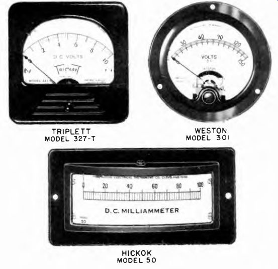
Fig. 10-1. Photographs of typical, modern panel meters. (Note: The above photos
are reproduced through the courtesy of the manufacturers indicated.)
Potential to Ground. A factor in whether a meter is to be mounted on any kind of metal panel is the potential to be applied to the meter circuit. For example, if current is to be indicated by a meter in a 1,000- volt B-(- plate lead, this high potential will exist between the current carrying parts of the meter and the grounded panel. In this situation, the meter case should be made of insulating material, and not metal; manufacturers' recommendations should also be consulted in this respect. Most panel type meters are housed in insulated cases.
Adapting Meters. Panel type current meters of suitable current rating can be adapted to voltmeter use by means of series multipliers.
When the meter is mounted upon a panel the multipliers are located outside the meter case, but must be protected against flash-over to the metal panel or low potential points which may be nearby.
In the event that a portable voltmeter such as a volt-ohm-milliammeter or a vacuum-tube-voltmeter becomes inoperative, a panel type current meter can be adapted to voltmeter use.
Most current meters contain internal shunts. These may be removed as a' means of increasing the meter sensitivity (reducing full scale current rating) in order to make the meter suitable for use as a voltmeter, with the proper multipliers based on the current rating of the movement. Removal of the internal shunt must be done with great care. Then it becomes necessary to determine the full-scale current range of the shunt-less meter movement.
Fusing Meters. If possible it is sound practice to add a fuse to metered circuits. A fuse protects the meter from damage by excessively high currents. A suitable fuse rating is slightly above the value of full-scale current the meter can indicate. All but thermocouple and hot-wire meters can ordinarily stand a several hundred percent overload for a short period; consequently, a fuse rated at 100 percent higher than the full-scale meter reading can still give protection. The fuse should be placed in series with the meter.
Special Panel Meters. Panel meters with certain special features are available. For example, some are hermetically sealed to keep out harmful dust and moisture, others are constructed with special mechanical features to withstand shocks, and are classified as "ruggedized." Another special feature is the illuminated dial, in which a small panel lamp mounted inside the case lights up the scale. Extra leads are brought out to a separate source of emf for this lamp.
10-2. Volt-Ohm-Milliammeter (VOM's)
These have the basic panel-type meter movement combined with switching and adjusting devices to adapt them to read various ranges of voltage, current, and resistance, and with metallic rectifiers when intended for a-c measurements.
Typical VOM's are illustrated in Fig. 10-2. These are 1,000 ohms- per-volt and 20,000 ohms-per-volt types. The following features are generally common to this type of instrument:
Meter Movement. The movement is a standard moving-coil device with a scale especially calibrated for its various functions. Meter movements intended for this application are designed to be used in any of a variety of physical positions.
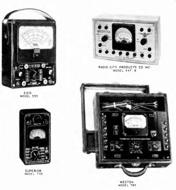
Fig. 10-2. Photographs of typical, modern volt-ohm-milliammeter. (Note: The
above photos are reproduced through the courtesy of the manufacturers indicated.)
Function and Range Selector Knob. This is used to manipulate the selector switch in the instrument, which connects the various shunts and multipliers into the circuit. The selection of a-c or d-c operation is made either by the main selector knob or by a separate knob provided for the purpose. In the latter case, the same voltage positions are used for both ac and dc. Usually three current scales (10, 100, and 500 ma) are provided.
In some VOM's, provision is made for reading currents up to 10 amperes full scale. When measuring such high currents, be certain that the connecting leads are making good contact and are heavy enough to carry the current. The leads must prevent very low d-c resistance to avoid undue voltage drop which might disturb the circuit being tested.
It is also important that the selector switch inside the instrument make good contact, or serious error may develop. The selector knob should be checked each time the instrument is used to make sure that it is securely fastened to the selector switch shaft; if it should shift, the wrong scales may be indicated and the meter overloaded or burned out.
Ohmmeter Zero Adjuster. When the selector is turned from one ohms scale to another, it is often necessary to reset the pointer at zero.
In some cases these instruments may have two ohmmeter scales, one labeled "hi" and the other "lo" ohms. The scales run in the same direction (zero at the right) so both are of the series-type ohmmeter circuit and are zero adjusted with the test prods shorted. In some VOM's a shunt-type ohmmeter circuit is used for low ohms, and the pointer must be adjusted at the other end of the scale with the test prods open.
Tip Jacks. Some instruments use tip jacks into which the test leads are plugged. A jack labeled "COM," meaning common, is the one into which the negative lead is inserted. For all scales, except the high voltage or high current, the positive lead is plugged into a separate jack provided for that purpose. Special jacks for high-voltage or high-current scales generally are in a different location from those used for other voltage and current scales, so as to be well-insulated and isolated.
Input Resistance of Instrument. As has been explained, (Sec. 3-15 and 3-17) the total resistance of the meter on any voltage range is equal to the full-scale voltage times the meter sensitivity.
Regardless of the input resistance factor, it is always best to use the highest voltage range consistent with an indication at least one-quarter of the full scale. The order of accuracy in reading ohmmeter scales at the very high resistance end of a range is usually low because the calibrations are quite crowded. Whenever possible the range chosen should be such as to cause the meter pointer to be somewhere in the first three-quarters of the scale.
Volt-ohm-milliammeter never should be left set for ohmmeter operation; this would drain the battery. If an OFF position is provided, the selector switch should be set to OFF VACUUM-TUBE VOLTMETERS
One advantage of the VTVM is its high input resistance on all ranges, of die order of 11 to 20 megohms. Some of these devices present an input resistance as high as 30 to 1,000 megohms on all a-c ranges.
For a-c measurements the input impedance varies greatly among different models. Information concerning this appears in Section 9.
The meter movements are the same in all VTVMs, namely moving coil permanent-magnet types, even though the ranges and kinds of scales differ. An idea of this can be had from Fig. 10-3, wherein are illustrated a variety of instruments. Among these is the center-zero scale.
As far as d-c quantities are concerned, the majority of VTVMs are designed for the measurement of voltage and resistance. Only a few laboratory type special purpose instruments provide means for direct current measurement. On the other hand, measurement of a-c quantities is limited to voltage, although in a few instances provision is included for the measurement of capacitance. The frequency range for a-c voltage measurements extends from about 20 hz to several hundred megacycles.
Only in rare instances is the upper frequency limit restricted to within the a-f band.
OPERATION OF VTVM
In most cases the VTVM function desired is selected by means of a switch labeled SELECTOR. The range generally is chosen by means of another switch, usually of the rotary type, marked RANGE. Frequently the range selector bears markings relating to more than one function; for example, d-c resistance and d-c voltage may be shown side by side or above each other. Sometimes the a-c scale also is selected by the same range switch. In some cases both range and function are chosen by the use of tip-jacks into which the leads are plugged.
An example of the last mentioned arrangement is the battery operated Hickok 214 VTVM shown in Fig. 10-3. One tip-jack serves as the "hot" connection for the test lead when making d-c voltage measurements in the 3-1,200 volt range, another tip-jack serves as the input connection for a-c voltage measurements between 3 and 300 volts, and a third tip-jack is used when making a-c measurements between 300 and 1,200 volts.
In contrast, the Triplett Model 650 VTVM shown in Fig. 10-4 uses a different arrangement. The a-c and r-f voltage measurements are made via a probe which plugs into a coaxial fitting. All d-c voltage and resistance measurements, on the other hand, involve a tip-jack. When a change in polarity of a d-c voltage measurement is encountered, the required reversal of the test connections is accomplished by means of a polarity selector switch marked -V and +V. In the RCA voltohmyst, shown in Fig. 10-5, polarity reversal is accomplished by the rotary selector switch.
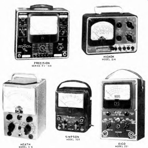
Fig. 10-3. Photographs of typical., modern vacuum-tube voltmeters. (Note:
The above photos are reproduced through the courtesy of the manufacturers indicated.)
Zero Adjustments. AH VTVMs which provide for d-c resistance measurement contain two variable controls of great importance. These are the electrical-zero adjust, whereby the electrical balance of the tube circuits is attained, and the zero adjust for the ohmmeter circuit. Markings for these controls generally are the same on most instruments, although it is not inconceivable that the electrical balance zero adjust may be confused with the ohmmeter zero adjust. A distinction usually is made between these two controls by labeling the ohmmeter adjustment as OHMS ZERO or OHMS ADJUST, whereas the electrical balance control is marked ZERO ADJUST.
The ohms-zero adjustment is a simple matter, but it is important to bear in mind that it is not independent of the electrical-zero adjustment. The latter also requires adjustment when the instrument is put into use. Both the electrical-zero and the ohm-zero adjustments require that the instrument as a whole reach temperature stability in order to avoid the necessity for continuous readjustment. In other words, before adjusting these controls it is necessary that a reasonable amount of warm up time be allowed (15 to 20 minutes warm-up time for all a-c operated devices, 5 minutes for battery operated devices).
VTVM devices are designed to be stable by making the vacuum tube circuits highly degenerative. In spite of this, readjustment of all controls is occasionally necessary. When the instrument is set from a high range to the most sensitive range, from 1 to 5 volts, a grid current voltage drop of from .1 to perhaps .3 volt across the entire input divider can cause quite a change in the zero setting. This possibility must be watched. An increasing need for electrical-zero readjustment is a sign of improper operation developing in the instrument.
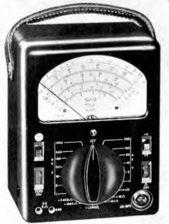
Fig. 10-4. Triplett 650 VTVM.
Precautions must be observed in the ohms-zero setting when changing resistance ranges. Instruments are designed for constant ohms zero on the different resistance ranges, but things do happen and erroneous readings can be the result unless the zero adjustment is correct. As a safeguard against wrong resistance measurements, check the ohms-zero adjustment each time the ohmmeter range is changed. Do not take a correct zero adjustment for granted.
For d-c resistance measurements, the non-uniformity of the VTVM scales tends to limit ease of reading to the first three-quarters of the scale, although about nine-tenths of the scale is definitely usable. Whenever possible, the scale should be such as to cause the pointer to swing not higher than three-quarters of full scale.
The on-off switch of battery-operated VTVM devices should be turned off when they will be out of use for any extended period. Difficulty in zeroing the instrument is usually an indication of run-down batteries.
10-3. R-F Measurements with Probes
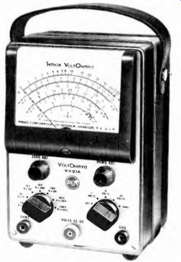
Fig. 10-5. RCA Volt-ohmyst.
VTVM probes for r-f measurements are shielded and grounded, and therefore should be immune to external fields. What may be true in theory, however, is not necessarily true in practice. When measuring an r-f voltage at a point located near another source of r-f voltage, both fields may contribute to the final indication of the instrument. To minimize these effects, the probe tip length should never be made greater than provided for in the design of the instrument. Hanging an extra length of wire onto the probe tip for the sake of convenience in measurement is not recommended. (See Fig. 10-6A.) The higher the frequency of measurement the more undesirable is this practice.
Experience also has shown the disadvantage of grasping the r-f probe head in such a way that the hand is very close to the probe tip. Body capacitance effects may introduce extraneous voltages.
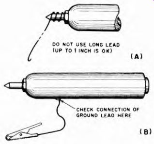
Fig. 10-6. (A) Addition of a piece of wire to the tip of the r-f probe may
introduce error. (B) A long or defective ground lead can also cause trouble.
A local field may produce a high and false indication when the probe tip is not in contact with the point of measurement. The free probe tip presents a high impedance across which a relatively high voltage is induced. When the probe tip is placed in contact with a test point the impedance between the probe tip and ground usually is lower, and the pointer drops to the proper indication.
R-f probes used with VTVMs provide for grounding at the point of probe contact or close by. The higher the frequency of measurement the more important it is to have a short ground connection. A sign of poor grounding is the inability to repeat a measurement with the same indication when the location of the ground connection is changed. When the ground connection issues from the probe it is important that the contact it makes with the probe be perfect. The flexing of these cables during continuous use of the probe frequently damages the wire at the point of connection; strands of multi wire cable sometimes become broken, thus increasing the r-f resistance of the ground connection. The result is an unstable indication which changes with changes in probe position. (See Fig. 10-6B.)
When making r-f measurements, sine-wave voltages are assumed by the instrument manufacturer unless otherwise stated. For voltages of different waveform, even when within the frequency passband of the probe, correction factors must be applied. Such correction factors usually are furnished with the instrument if needed.
PART I - GENERAL ELECTRICAL TESTS AND MEASUREMENTS
10-4. Testing Batteries
Unless a battery has been dead for a long time, a no-load voltage test made by connecting a voltmeter across it is not truly indicative of battery condition. As the battery deteriorates its internal resistance increases; to detect this the test must be made by placing a load across it.
One way to check the condition is to connect a resistor of the proper value across the battery, so that the normal load current will flow through it, then apply a voltmeter. The resistor and meter can be found in one instrument called a "battery tester" (Fig. 10-7); instruments with a number of ranges for different types of batteries are available. In these, a multiple switch selects the load resistor and voltmeter range required for each type of battery. The application of a conventional voltmeter for this purpose is shown in Fig. 10-8.
A good general rule is to replace dry batteries which have dropped below 70 to 80 percent of their rated voltage under load.
10-5. Battery Charging
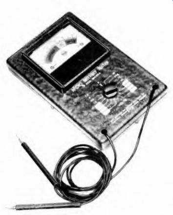
Fig. 10-7. RCA battery tester.
Figure 10-9 (A) shows a simple battery-charging setup. The ammeter is connected in series with the battery to indicate rate of charge. The rate of charge depends upon the difference between the charger voltage and the battery voltage. Rates of charge actually used vary from a fraction of an ampere for small "trickle" chargers up to 100 amperes for large "quick-charge" units. A recommended normal maximum charging current is from 5 to 10 amperes.
In some applications charging takes place while the battery is in use, as in automobiles. If, as in cars, the charging rate as well as the discharging rate varies, the net current may be charging or discharging the battery. To measure this net battery current, a center-zero ammeter is used (Fig. 10-9 (B)) ; if the pointer moves to the right, the charger current exceeds the load current by the indicated amount. If the load current is larger, the pointer moves to the left of zero.
10-6. Checking Equipment Current Drain
The circuit in Fig. 10-9C shows how to measure the current drain of single phase a-c operated devices such as electric irons, clocks, toasters, fans, radio or television receivers, etc. A rough approximation of the required range of the current meter is 1 ampere for each 100 watts of power rating of the device. In the case of irons or toasters and other devices which do not reach temperature stability immediately, the current range of the meter should exceed that calculated as stated above, because of the initial surge of current.
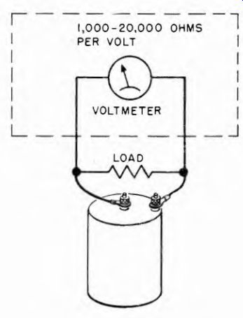
Fig. 10-8. Determining terminal voltage of a battery.
If the unit is d-c operated, the same circuit applies, except that the current measuring device is a d e meter, although the a-c moving-vane or dynamometer types of meters will function satisfactorily.
A more suitable method of measuring the current drain of low power devices which require some time to reach temperature stability, during which time the current changes, is shown in Fig. 10-9D. An a-c voltmeter (or a d-c voltmeter, depending on the kind of current involved) is connected across a series resistor and the voltage across this resistor is measured. The current drain then can be determined by the application of Ohm's Law for current or I = E/R where I is in amperes, E in volts and R in ohms.
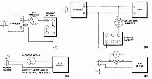
Fig. 10-9. (A) An ammeter connected to indicate rate of battery charge. (B)
A center zero meter used as a charge-discharge instrument. (C and D) Ammeter
and voltmeter connected to measure current drain and power of device operated
from the power line.
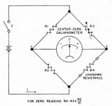
Fig. 10-10. Wheatstone bridge circuit for measuring resistances.
A 1-ohm resistor rated at 25 watts is rated at a maximum current of 5 amperes, and a 5-ohm 25-watt resistor at about 2.5 amperes. The arrangement shown in Fig. 10-9D is suitable only if the power rating of the device does not exceed 100 watts.
10-7. Center-Zero Galvanometer in Wheatstone Bridge
Although most ordinary resistance measurements are made with an ohmmeter, there are some cases in which greater accuracy than that of the ohmmeter is necessary. The Wheatstone bridge (Fig. 10-10) provides the desired accuracy for checking and measuring such things as shunt and multiplier resistors, calibrated (frequently a decade resistance.
R3 is a variable resistor accurately resistance box) . R4 is the unknown
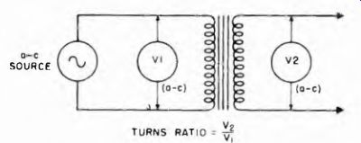
Fig. 10-11. Method of measuring turns ratio of a low-frequency transformer,
if V2 is higher than VI the turns-ratio is step up; if V2 is less than VI the
turns-ratio is step down.
SOURCE
The bridge is said to be balanced when the current / is divided between the R2 and R4 branches in such a way that the voltage between points a and b is zero. The center-zero galvanometer indicates this condition by reading zero when R3 is properly adjusted. The relation given in the diagram can then be used to determine R4. Resistors R1 and R2 need only have a known ratio. They are usually selected as pairs, with ratios in powers of 10, such as 1, 10, 100, 1,000, etc.
When a measuring system is adjusted for a balance indicated by zero or minimum current, the balance condition on the meter is referred to as a "null." Meters used in this way are often referred to as "null meters." A VOM or VTVM can be used as a null meter.
10-8. Power A-F, and Supersonic Transformer Turns Ratio
Figure 10-11 shows a method for measuring the turns ratio of power or audio transformers. An a-c voltage is applied to the primary winding.
The a-c voltage across the primary winding (V1) and the a-c voltage across the secondary winding (V2) are then measured. Voltage is proportional to turns in this kind of a transformer, so the turns ratio is equal to V2/V1. If a heavy load is applied, the voltage ratio drops considerably below the turns ratio due to voltage drop in the windings.
10-9. Low-Frequency Impedance Measurements
A simple circuit for the measurement of any type of impedance at low frequencies is shown in Fig. 10-12. The impedance to be measured, Fig. 10-12. The unknown impedance Zx is measured by comparing the voltage drop across Zx with the voltage drop across the standard resistor Rs.
Zz, is placed in series with a non-inductive variable resistance, R„ and connected to a source of low-frequency voltage. When the resistor R„ is adjusted so that the voltage El across R„ is equal to the voltage E2 across Zz, then Zz is equal to the value of R„. Rs can be measured readily with a good ohmmeter or bridge, if it is not already indicated in a direct-reading resistance box. The unknown impedance also can be found from the following equation:
Zz = RtEl_ E2
Because of the effect of stray capacitance, this method of measuring impedance is most suitable at power and audio frequencies. For low impedances, the method will give accurate results up to low radio frequencies.
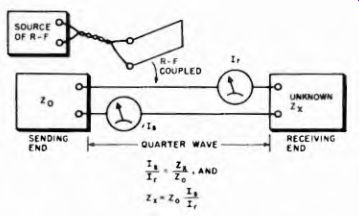
Fig. 10-13. How the r-f impedance of a device may be determined by use of
a quarter wave line and two thermocouple r-f ammeters.
10-10. Measuring R-F Impedance with a Transmission Line
A quarter-wave transmission line can be used to measure impedance (Fig. 10-13). The line is terminated at the sending end by its characteristic (surge) impedance, and the impedance to be measured ...
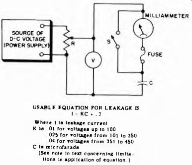
Fig. 10-14. Arrangement for measuring leakage current of capacitors.
USABLE EQUATION FOR LEAKAGE IS I KC + . 3
Where I Is leakage current K is . 01 for voltages up to 100
. 025 for voltages from 101 to 350
. 04 for voltages from 351 to 450 C is microfarads
(See note In text concerning limitations in application of equation. )
... is connected at the receiving end. R F current is then coupled into the line, and thermocouple ammeters are connected as shown. The ratio of the sending-end current (Is) to the receiving-end current (IR) is then the same as the ratio of the unknown impedance (Z/ to the characteristic impedance (Zo) . The formula for Zx is shown below the diagram.
10-11. Bridge for Measuring Impedance
Impedance of any kind can be measured by means of a bridge circuit. The principle is exactly the same for the Wheatstone resistance bridge, except that variable standard impedance and an unknown impedance replace R3 and R4 respectively (see Fig. 10-10), and the source of emf must provide a-c voltage instead of dc. The meter indicates alternating current without regard to polarity, the null being a minimum alternating current rather than a balance between plus and minus. For low frequencies the meter can be a rectifier type. At higher frequencies in the r-f range it must be a thermocouple milliammeter or a high- frequency probe connected to a VTVM. Note that the measurement accuracy does not depend upon meter accuracy in the usual sense, but rather upon how small a current change or minimum it can detect and on the accuracy of the standards.
10-12. Measuring Electrolytic-Capacitor Leakage Current
Leakage impairs the efficiency of electrolytic capacitors. A method for checking leakage is illustrated in Fig. 10-14. The capacitor is connected across a power supply which can be adjusted to provide the full rated working voltage. The milliammeter is connected in series with the capacitor, and the polarity of the applied voltage must conform with the polarity of the capacitor being tested. The switch S is very important and must be provided. This is because a large surge of current will flow into the uncharged capacitor when the voltage is first applied, and this surge might burn out the meter. The switch is kept closed until the capacitor has had about 5 minutes to charge. Then it is opened for a reading. Alter the switch has been opened, allow 1 minute of ageing time for each month of shelf life before checking the leakage current.
The fuse is added to protect the meter in case the capacitor shorts during the test, or in case the switch should accidentally be left open when voltage is applied.
Almost any kind of milliammeter whose range is suitable for the leakage-current value is satisfactory, and sensitivity should be judged accordingly. A meter with a maximum range of 25 milliamperes is ordinarily satisfactory. The formula of Fig. 10-14 helps determine allowable leakage, which is the calculated 1 or 10 ma, whichever is smaller.
10-13. Testing Fixed-Capacitor Insulation Resistance (Leakage)
The insulation resistance of a fixed paper, mica, or ceramic dielectric capacitor is an important rating. Insulation resistance as low as 1,000 megohms can cause trouble if the capacitor is used as a d-c blocking element between the plate of one vacuum tube and the control grid of another.
KEEP SW. CLOSED WHEN FIRST APPLYING VOLTAGE OPEN AFTER 10-15 SECONDS.
SOURCE OF D-c VOLTAGE I00-5O0 VOLTS POWER SUPPLY 50 MICRO-AMPERE METER
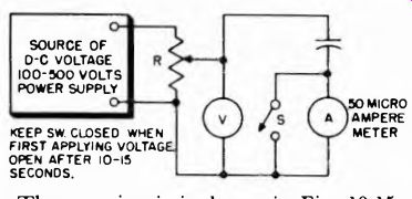
Fig. 10-15. Circuit for measuring insulation resistance of paper-mica-or ceramic-dielectric
capacitors.
The test circuit is shown in Fig. 10-15. Mica and ceramic dielectric capacitors should display between 5,000 and 7,500 megohms insulation resistance with 250 volts dc applied. Assuming an insulation resistance of 5,000 megohms, the current would be 0.05 microampere, hence causing almost imperceptible deflection, if any, on a 50-microampere meter. A meter deflection in excess of the barest movement of the pointer on such a meter, therefore, would be a sign of insufficient insulation resistance or excessive leakage. For other applications, as for example bypassing across relatively low values of resistance, a lower insulation resistance is allowable than for d-c blocking. The ordinary ohmmeter test is useless for such checking because the applied voltage is too low.
Paper dielectric capacitors display lower insulation resistance than mica or ceramic dielectric units. The usual rating is from 1,000 to 2,000 megohms per microfarad at rated d-c operating voltages. Investigation
Fig. 10-16. Use of a-c source and current meter to measure capacitance. The a-c voltage source can be an isolation transformer with 120-volt output.
I = CURRENT IN AMPERES
E = VOLTAGE IN VOLTS
f = FREQUENCY IN HZ
c « capacitance in farads
of paper dielectric capacitors in perfect condition discloses that values as low as .1 ^f display insulation resistances of 1,000 megohms or higher.
Somewhat lower values of insulation resistance do not necessarily indicate a defective condition; the determining factor should be the leakage in the specific circuit where it is used.
10-14. Measuring Capacitance by the Current or Comparison Method
One way to measure capacitance is by its reactive effect in an a-c circuit. The greater the capacitance the lower its reactance at any one frequency, and the greater the current which will flow in the circuit.
A circuit for such measurement is shown in Fig. 10-16. The a-c meter used is a milliammeter, preferably of the multi-range variety, intended for 60 hz operation, since the voltage source generally is the 60-cycle power line. This test generally is restricted to capacitors higher than .5 ^f, hence the lowest current scale required is about 0-50 milliamperes.
The current for a .5-^f capacitor with 120 volts ac applied is about 22 milliamperes. For a 50-p.f capacitor, with the same voltage applied, the current is about 2.2 amperes.
The formula under the diagram shows how to calculate the capacitance when the current and the applied voltage in the circuit are known.
The method shown cannot be used for capacitors with an appreciable resistance component, or leakage such as electrolytics. If leakage is present, the current I is the result of this leakage as well as the capacitive reactance, and thus does not indicate capacitance alone.
A simple comparison method for measuring capacitance is shown in Fig. 10-17. The unknown is compared with a known capacitance by noting the voltage drop across a 50-ohm resistor placed in series with the capacitor. The test is made first with the unknown capacitor (C,) in the circuit (S in upper position) . Then the position of S is changed and a known capacitor from the decade box is inserted in the circuit.
The decade-box selector switches are varied until substantially the same...
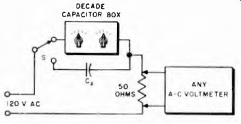
Fig. 10-17. Comparison method for measuring capacitance.
...amount of a-c voltage is indicated across R for both capacitors. The unknown capacitance then has the value indicated by the settings of the selector switches on the decade box.
10-15. Measuring Inductance Capacitance by Resonance Effect
The following relation exists between inductance, capacitance, and frequency in a resonant circuit in which resistance is relatively low where f is frequency in hz L in henries C in farads...
25.33 Ll = f2cs
...where f is frequency in megacycles L is inductance in millihenries C is capacitance in micromicrofarads crystal or diode.
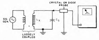
Fig. 10-18. By using the volt voltmeter to determine the resonant frequency
and selectivity of the tuned circuit, it is possible to measure inductance,
capacitance, and resistance.
This relation is applied in a number of methods to measure capacitance and inductance. One of these methods is illustrated in Fig. 10-18.
A standard capacitor (Cs), whose exact capacitance is known, is connected across an unknown inductance Lx whose value is to be determined.
NO-LOAD VOLTAGE (R REMOVED) Ef=FULL-LOAD VOLTAGE(AT RATED CURRENT)
A signal from a signal generator is loosely coupled into Lx as shown, and the voltage across the parallel combination indicated by the VTVM. This meter must be suitable for the frequency at which the measurement is to be made. For any but the lower radio frequencies (below 500 khz) the high-frequency probe of the VTVM should be used.
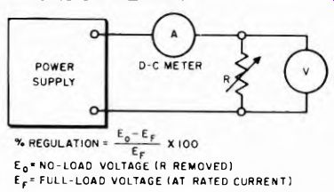
Fig. 10-19. Determining voltage regulation of a power supply.
The signal-generator frequency is then varied until the VTVM indicates maximum voltage, with a sharp drop-off on either side of the adjustment. The resonant frequency, as indicated on the signal generator, plus the known value of the standard capacitor Cs can then be substituted in the resonance formula to obtain the value of Lz.
The same setup can be used for measuring an unknown capacitance with an inductance as the known standard. The capacitance Cs in the equation is replaced by Ls, and Lx is replaced by Cz.
10-16. Power-Supply Regulation
The voltage regulation of a power supply is of interest because it indicates how well the voltage remains constant with a varying load.
The regulation of a supply can be determined by measuring the output current and voltage for various loads, as shown in Fig. 10-19. The percentage of regulation is defined in the equation just below the schematic diagram. The power rating of the variable resistance R must be adequate for the load applied. If voltage is plotted against current for different loads, a graph something like that in Fig. 10-20 results.
10-17. Power-Supply Ripple
Ripple is the a-c voltage superimposed upon the d-c voltage output.
Its percentage of the total output voltage is an indication of the Fig. 10-20. Typical voltage regulation characteristic.
CURRENT efficiency of the power supply filter circuit. Figure 10-21 shows how ripple may be measured. The voltmeter (V1) measures the d-c voltage output; the voltmeter (V2) measures only the a-c component. The two voltages can then be used to obtain the percentage of ripple. Ripple percentage increases with increasing load current, so the test must be made at a particular desired current load, or several specified load values.
The load resistor R is connected across the output, and the load current is checked with the meter MA. The range of MA must be adequate for ...
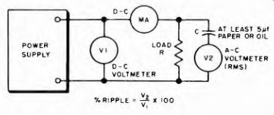
Fig. 10-21. Method of determining ripple in the output of a power supply.
... the current loads at which the tests are to be made. The capacitor C keeps direct current out of the a-c meter; its capacitance must be great enough so that its reactance is small compared to the load and meter resistances. For full-wave rectifier supplies (120- hz ripple), C should be at least 5 pf. For half-wave supplies (60-hz ripple), higher values must be used. The meter MA may be a panel meter or the direct current meter in a VOM or VTVM.
PART II - APPLICATIONS IN RADIO AND TV RECEIVERS
Most meter applications in receivers are ones in which an external meter is employed, usually a VOM or a VTVM with suitable ranges.
In general, it may be said that the primary use for meters in receivers is in servicing them, and the following pages are written accordingly.
10-18. Where to Make Meter Measurements in Receivers
When trouble develops in any receiver, a variety of tests may be called for. As far as meters are concerned, the two general categories of tests are (1) d-c resistance, and (2) operating voltages. The latter may be ac as well as dc, depending on the circuit in question, although d-c measurements far outnumber a-c measurements in practice. D-c measurements embrace both current and voltage, although current measurements are not too frequent.
D-C Resistance Tests. D-c resistance tests are made with the ohm-meter. The primary power switch on the receiver is turned off and the power plug is removed from the power line socket. Another worthwhile precaution is to allow a few minutes for the power-supply capacitors to discharge. Even then it is a good idea to discharge an and all large capacitors in the equipment being tested, by momentarily short circuiting them to ground with a screw driver.
While ohmmeter measurements can be made without removing the chassis from the cabinet, it is recommended that the chassis be removed so that all components are readily accessible.
Tube Sockets. D-c resistance measurements can be made from the top of the tube sockets by removing the tubes and using one ohm
meter lead as the roving probe, the other lead being connected to a common reference point, usually ground or the chassis, whichever is recommended in the service notes. When individual components are checked for d-c resistance, the ohmmeter probes are connected directly
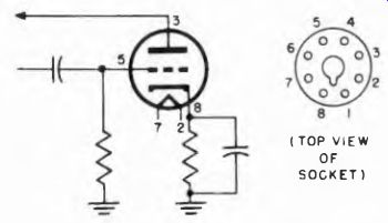
Fig. 10-22. How tube socket connection points are indicated by numbers on
the schematic diagram.
( TOP VIEW OF SOCKET)
across the terminals of the component. These measurements are treated in more detail later in this section. Whatever is said here about using tube sockets for resistance measurements is applicable to voltage tests too.
Assuming that the chassis is the common reference point while working with the tube sockets, the following aids are suggested: First, the schematic of the receiver should be on hand for comparison purposes; this is important for learning which socket terminals are alive relative to the tube circuitry. Some receiver manufacturers use some of the free socket terminals as tie-points for attaching capacitors or resistors which may not be directly tied to active tube electrodes. The tube symbols on the schematic show which are the active tube-socket terminals by the numbers adjacent to the tube electrode symbols. This is illustrated in Fig. 10-22.
Although the top view of an octal socket shows eight holes, when there is a triode tube in an octal base only six pins( 1, 2, 3, 5, 7, and 8) are used. Socket terminals 4 and 6, therefore, can be used as tie points.
It is very important to realize that the schematic representation of the circuit does not show such tie points, or whether they exist. These become evident only when the underside of the chassis is examined.
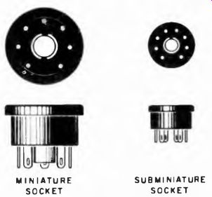
Fig. 10-23. Top and bottom views of miniature and sub-miniature sockets.
MINIATURE SOCKET SUBMINIATURE SOCKET
Many octal sockets have only five active terminals (for a five-pin tube), and others make use of every terminal, because the tube inserted in the socket has eight live electrode connections. Other kinds of sockets may bear more than eight terminals, depending on the tube used, and all or only some of them may be active. Top and bottom views of other kinds, called miniature and subminiature sockets, appear in Fig. 10-23.
Contact with socket terminals for d-c resistance measurements is possible without inserting the ohmmeter probe into the socket pin holes. Adaptors with exposed connecting tongues are available for this purpose; as many tongues protrude as there are pins on the adaptor.
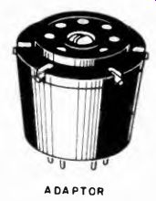
Fig. 10-24. A drawing of an adaptor with exposed tongues.
ADAPTOR
An example is shown in Fig. 10-24. The bottom of the adaptor has pins for insertion into the tube socket, and the top of the adaptor has holes for insertion of the tube, thus permitting measurements with the tube in or out of the socket. Adaptors are available to accept almost all types of receiving tubes, even picture tubes.
All d-c resistance measurements need not be made relative to ground. When desired, these tests can be made between any two socket pins by joining the ohmmeter leads to the appropriate points, just as if they were the connections from a component.
NUMBERS; NUMBERS ( READ CLOCK WISE ) BOTTOM VIEW (AS VIEWED FROM UNDER THE CHASSIS) READ COUNTER CLOCKWISE .
TOP VIEW (AS VIEWED FROM TOP OF CHASSIS) NUMBERS READ CLOCKWISE SCHEMATIC VIEW (BOTTOM VIEW, ALWAYS GIVEN)
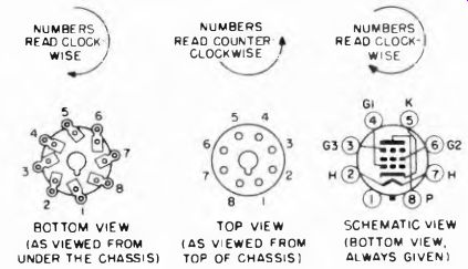
Fig. 10-25. Relation between the top and bottom views of an octal socket and
schematic diagram of the tube as it would appear on a circuit diagram.
The illustrations in Fig. 10-25 correlate the bottom and top views of an octal socket. Although an octal socket is shown here, the same direction of travel when counting the pins and terminals applies to all other types of round receiving-tube sockets. Because they are being
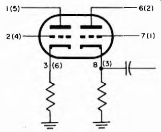
Fig. 10-26. Alternate numbers adjacent to tube pin symbols indicating difference
in numbers when alternate tubes are used in socket.
viewed from opposite directions, pin numbers run in opposite directions in top and bottom views, although the same pin number always applies to the same pin. For applications in which an alternate tube is suggested, a receiver schematic may show two sets of pin numbers. An example is given in Fig. 10-26. The alternate tubes in this instance are a 12AU7 and a 6SN7GT.
D-C Resistance Tests on Components. Sometimes d-c resistance measurement is made with the chassis as the common reference point.
Sometimes it is made directly on the component. In either case, a multi-range ohmmeter should be used and the range which affords a convenient indication chosen.
Variable Capacitors and Air and Mica Trimmers. Shorts in these components may be complete, or they may occur over only a portion of the complete range of adjustment. However, in addition to direct short circuits, high-resistance leaks- may exist between terminals as the result of dirt, dust, or cracks in the insulation. Hence, a measurement capable of showing a short circuit alone is not sufficient, and measurements capable of showing leakage resistance of several megohms also should be made. Normally air and mica dielectric units will show virtually an open circuit between the active plates. When checking these units, it is recommended that they be varied through their full range of capacitance.
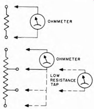
Fig. 10-27. When the resistance of a tapped resistor is being measured, each
tap should be checked against a common point at one end, as indicated by this
Figure. In addition, if the resistance of one section is relatively low, a
separate reading directly across it is in order.
Fixed and Tapped Resistors. All fixed resistors are treated in a similar manner, the measurement is made between the extreme limits of the resistor in order to determine the total resistance. This is obvious if the resistor has only two terminals; but, when it has taps, an overall resistance measurement will not disclose the resistance between the taps; a connection to one of the taps may have opened up. Using one end as common, a measurement should be made at each terminal. If the resistance between taps is low relative to the overall resistance, individual measurement should be made between the low-resistance taps (Fig. 10-27).
When measuring the d-c resistance of receiving-type resistors used in high-frequency circuits, bear in mind the possibility of improper frequency characteristics of the resistor. Certain types of these resistors show a very great decrease in resistance to VHF and UHF currents. Yet, when measured with d-c voltage applied, they show the normal ohmic values. Therefore, make certain that the resistor is of the proper type relative to its frequency characteristic.
It is essential that good, firm contact between the ohmmeter probes and the measured component be made. This is particularly important at low resistance values, where contact resistance can raise the reading to far above the true component value. Tolerances in resistance values (often given on schematics) are normally from ±5% to ±20%, and can be greatly exceeded by contact resistance as above.
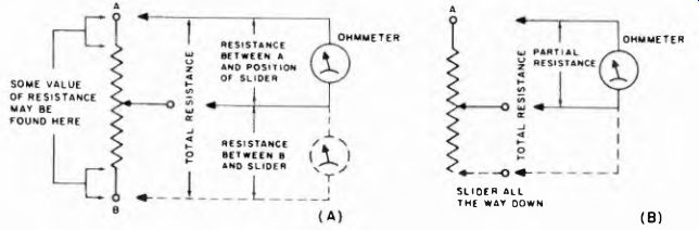
Fig. 10-28. Diagrams illustrating the measurement of variable resistors.
Variable Resistors. These are encountered in all types of electronic equipment, especially television receivers. The total resistance is measured from one end of the element to the other, as with fixed resistors (A to B in Fig. 10-28 (A)). In rheostats, the slider must be moved to the unterminated end, as in Fig. 10-28 (B) The resistance test of a potentiometer is not complete until the resistance between all positions of the moving arm and one end of the element has been observed as the arm is moved through its range. In a few special components, resistance between the arm and the element may not drop to zero even when the arm is adjusted to its minimum resistance position; this is normal for types designed to include a small extra fixed resistance (25-1,000 ohms) as an extension of the main element.
Sometimes the moving arm of the control is purposely grounded to the case (shield and shaft) and sometimes it isn't. A continuity test between arm and case is thus in order, and the result can be checked against the schematic diagram.
Some controls do not provide for a continuous change in resistance over the full arc of travel of the moving arm. Sometimes a fixed resistance section of from 25,000 to perhaps 100,000 ohms may be a part of the potentiometer, in which case there will be no change in resistance as the moving arm is rotated over this section. Finally, the order of change in the ohmic value as the moving arm is advanced across the resistive element is not always the same, because the tapers are not alike. A linear taper is one in which the resistance change per degree of shaft rotation is constant as the moving arm is advanced from one limit of the resistive element to the other. Examples of different tapers are shown in Fig. 10-29.
Unfortunately, variable resistive controls do not bear labels stating the specific taper that is used. However, the function of the control usually determines the taper used, as indicated in Fig. 10-29. An abrupt change in resistance is not necessarily indicative of a fault in the unit; some controls are made that way.
In checking these controls with the ohmmeter, watch for jiggles and wiggles of the pointer as it moves across the scale. Such action indicates a bad sliding contact and a noisy control.
Resistance Test of Automatically Varying Resistors. A number of resistance components automatically vary in resistance with current through them. These cannot be checked for resistance with an ohm
meter. Instead they require the application of a fixed amount of current through the resistor and a voltage test across it. The resistance then is determined by Ohm's Law for resistance and compared with the reference information. Such units are the Globar. Thermistors, etc.
1. Left-hand logarithmic taper, used in ordinary shunt volume controls.
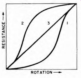
Fig. 10-29. Resistance variation and application of various tapers in volume
controls.
2. Right-hand logarithmic taper, used in series controls, such as variable cathode resistors.
3. Linear taper, used in test equipment and elsewhere where uniform variation is needed.
D-C Resistance Measurements on Inductor-Type Components. An inductor-type component is one in which performance is based on the property of inductance. Transformers, coils, chokes, speakers, and the like are examples of inductor-type components. A d-c resistance test made on such components is of limited utility; its main purpose is to show continuity. However, under certain circumstances, it is possible to determine such things as shorted turns, or shorted layers. For such conditions, the value of d-c resistance is substantially less than the normal value, or the coil shows an open circuit.
There is no difficulty in making a d-c resistance test on an inductor type component if its nominal value of d-c resistance is 1 ohm, or a substantial part of an ohm. Measurement with an ohmmeter can indicate a defect if the fault is such as to cause a substantial change in the d-c resistance of the winding. But if the coil consists of a few turns with a relatively low total ohmic value, shorted turns may cause only a minor change in the d-c resistance of the winding, yet a major difference in the a-c performance of the device. This always has been a problem, and the solution rests in making a-c as well as d-c measurements.
Slightly lower-than-specified coil resistance could be due to shorted turns or just manufacturing tolerance (10%), in which case a resistance test is not conclusive. Substantial resistance change does, however, indicate trouble.
If a resistor is connected across a coil, as in Fig. 10-30 (A), it should be disconnected when the coil is checked, unless of high enough value so that the shunting effect is negligible.
Some circuit arrangements may call for a coil in series with a capacitor, which may not be readily evident. (See Fig. 10-30 (B).) The presence of the capacitor in the d-c resistance path will result in an open circuit indication. When the ohmmeter is correctly connected across the coil proper, it indicates the d-c resistance of that device. Measurement made across the coil and capacitor in series may show continuity corresponding to the nominal ohmic value of the coil. This is a sign of a short circuit in the capacitor.
In the case of a coil paralleled by a capacitor, measurement across the combination should show the d-c resistance of the coil. (See Fig. 10-30 (C).) A lower than normal value of resistance may indicate a bad capacitor, or a bad coil. An open circuit indicates a bad coil. Another important test is to check between a coil and its core. There should be no leakage present.
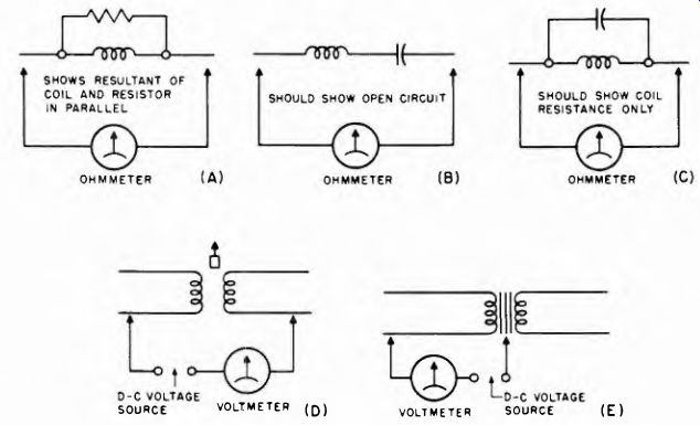
Fig. 10-30. Various combinations of coils, capacitors and resistors which
can be tested as explained in the text.
Sometimes a d-c resistance test shows normal, yet the units seem to go bad after being placed in operation and its temperature rises. This is possible, and means that the resistance test cannot be the deciding test, but that signal or other voltage tests have to be made while the unit is in operation. This occurs frequently with horizontal output transformers and sometimes with yokes. It can also happen with an inductor unit whose temperature rises substantially during operation.
Leakage between the winding and the core, or between windings, or between a winding and a shell, is a frequent problem that must be checked. A test voltage in excess of that usually found in the ohmmeter should be used, several hundred volts d e should be applied if possible.
Many devices subject to high voltages are designed to withstand 1,500 to 2,500 volts rms between windings, and between windings and core.
Electrolysis can readily cause a relatively high resistance leak between the winding and the grounded shell when the equipment is used in highly humid climates and where the salt content is high.
The methods of measuring are shown in Figs. 10 30(D) and 10-30 (E), and the insulation resistance should be up in the thousands of megohms. The voltage from a power supply approximating 300 or 400 volts is a good source of voltage; the meter can be a d-c voltmeter.
The insulation resistance should be high enough so that the meter indicates zero voltage even on the lowest range.
D-C Resistance Tests on Vacuum Tubes. Frequently it is necessary to test for shorts or leaks between the electrodes of vacuum tubes, and the continuity of their filaments. Before deciding that a short circuit exists, be certain that the short circuit indication is not the result of internal connections between two electrodes. Since some tubes call for this, tube charts must be checked to verify the condition. When such tests are made, the tube should be out of its socket and the tests made at the tube base pins.
When making continuity tests on tube filaments be certain not to apply the ohmmeter voltage to low voltage-low current filaments, because they will be burned out instantly. Check 1.5 volt and 2.5 volt low current tubes by applying a low voltage with a current meter in the circuit. The applied voltage need not exceed 1 volt and the current meter can be a 250 milliampere instrument. Continuity is indicated when the meter shows current flow; its exact value is unimportant.
10-19. Point-To-Point D-C Resistance Measurement
A trouble-diagnosing technique that is popular in radio receiver servicing, although it can be applied to all electronic equipments, is known as point-to-point d-c resistance measurement. In principle it is nothing more than measuring the d-c resistance between two given test points, or between a reference point and a number of different test points. The correct value of resistance for each test is known from manufacturer's or other data, either directly or from examination of the schematic diagram. If a test shows serious deviation from correct value, a defect in the circuit is indicated.
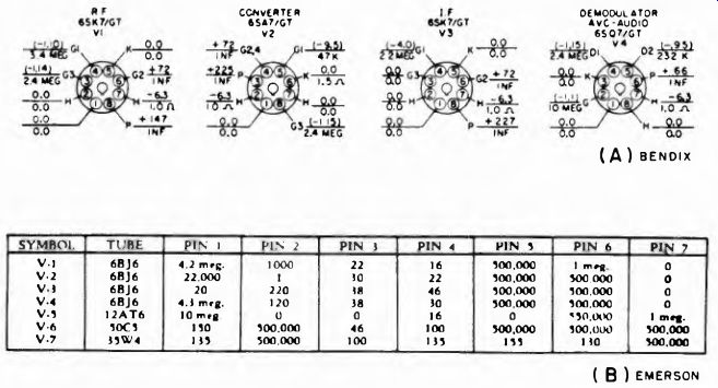
Fig. 10-31. Bottom view of radio chassis showing d-c voltage data and resistance
chart.
An example of the two methods of showing point-to-point d-c resistance data appears in Fig. 10-31. Sometimes the table of voltage data at the different tube socket terminals also bears the list of d-c resistance values between the same socket terminals and the common reference point, which is either chassis or ground.
The technique is applicable as a quick check of overall circuit continuity, or even circuit resistance when the information does not appear in chart form or on the bottom view of a chassis. In the latter case, the reference information is gathered directly from the schematic by tracing the circuitry to be checked and noting the constants of the circuit elements and their organization.
The point-to-point d-c resistance measurement technique is no different than the d-c resistance test made on an individual component, except that by selecting widely separate points as the test points all the components connected between these points are embraced at one time.
The Presence of Electrolytic Capacitors
An important point in connection with the use of an ohmmeter for trouble diagnosis is the presence of electrolytic capacitors across resistors being checked. The positive terminal of the ohmmeter should join the positive terminal of the electrolytic capacitor. Whenever possible it is recommended that the electrolytic capacitor be removed before the circuit resistance test is made. .
Still another item pertinent to successful application of the ohm-meter is that relating to the presence of selenium rectifiers. This device presents different values of resistance depending on the polarity of the voltage applied. A rapid means of eliminating the possibility of confusion because of the presence of these units is to deliberately short circuit the rectifiers by means of shorting wires.