To service a radio with the least expenditure of time, which is another way of saying to make the most money, involves three variables. First, there are the techniques which enable a serviceman to quickly and efficiently go about his business. Second, there are the various methods by which he uses his technique, each being useful in its particular place. The third variable is localization of the defect and its repair.
---------
When a receiver is delivered for servicing it is a good idea to use the customer's complaints as a guide in locating the difficulties. This requires some care, as it can lead to misunderstanding since many people are not as articulate as desired. An example is the complaint "the set doesn't work." This does not necessarily mean that the receiver is completely inoperative, or dead; it may mean that it is working, but so poorly as to have the customer consider it useless.
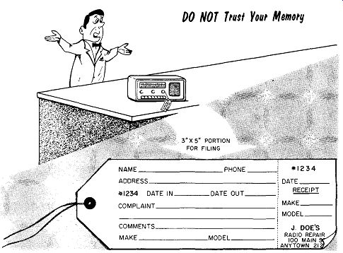
The first question to ask a customer is: "WHAT IS THE COMPLAINT?" never ask, WHAT IS WRONG? Obviously if they knew what was wrong, they would not need a serviceman. There are other leading questions that can be asked: How Jong has it been like this? How often does it happen? Does it happen any special time? Do not ask too many questions--the customer should not get the feeling he is being interrogated. Be sure to note the customer's complaints on a service tag; do not trust your memory.
Servicing Techniques
An important aspect of technique is to reason the difficulties. All too often the beginner is prone to guess-changing a component that looks bad-or worse yet, surmising that this just might be the difficulty. Logic will tell the serviceman to pause and reason what could cause this effect. Knowledge of the circuitry enables the serviceman to reason the nature of the difficulty, and perhaps its exact cause.
An example might be a 60-cycle hum in an ac-dc receiver. Usually this is a result of inoperative or ineffective filter capacitors. Most servicemen would quickly bridge the filtered capacitors with a good capacitor to reduce ...
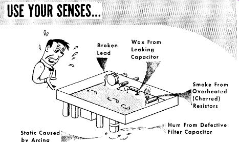
-------- Static Ca used' by Arcing Broken Lead Wax From Leaking Smoke From
Overheated (Charred)
1 Resistors, Hum From Defective Filter Capacitor
... the hum. Should this test fail the serviceman must then ask himself where else can 60-cycle hum be developed in the receiver. A moment's thought would remind him that it could be a cathode-to-heater short in a tube.
The subject of calm reasoning and logic versus guess work can not be over emphasized. Many servicemen find that from past experience they can readily learn the common types of troubles and often make quick repairs.
When the unusual trouble comes along that is not similar to the routine repairs, then reasoning separates the men from the boys.
Servicing Methods
----
There are different methods of approaching the job of servicing a receiver.
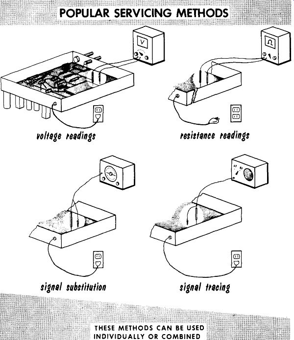
Each method has its devotee-some will insist this is the only way, and others will disagree. The four most popular methods of servicing are : servicing by voltage readings, by resistance readings, by signal injection, and by signal tracing. Each method has its merits. The individual service man may use methods that may consist of one of the four methods or a combination of any of them.
---
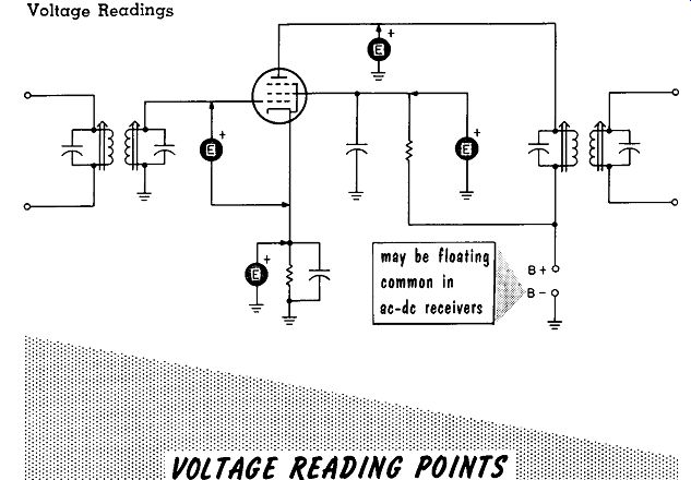
A good first step in servicing is to take voltage readings. With low or no voltages the circuits will not operate correctly or not at all. A quick step is taken by checking power supply voltages since these voltages are common to the entire receiver. The values of the measured voltage may vary from those listed on the schematic diagram. Changes in the line voltage can effect the voltage, and low emission of the rectifier tube can reduce the power supply voltage. The voltages measured may vary ±20%, usually minus, of the required voltage. A circuit that should have 250 volts applied may have only 200 to 300 volts. When a reading is low by almost the full 20%, it should be corrected even though it may not be the cause of the trouble in the receiver.
Typical voltage readings that can be taken, are shown in the circuit above.
In practice, the plate-to-cathode voltage can be approximated by taking a reading from plate to ground. The cathode voltage (in most cases) will be insignificant.
In checking voltages in ac-dc receivers, the chassis is usually not common B-; common is floating. In checking voltages in any receiver it is a good policy to determine whether the chassis is common or not. If any doubt exists a safe point to place the negative probe is the negative terminal of the power-supply filter capacitor.
Resistance Readings
An important precaution when taking ohmmeter readings is to be sure the receiver is turned off and the a-c plug removed from the line. In battery sets be sure to remove the battery. Resistance tests quickly check for open or short circuits, or changes in component values.
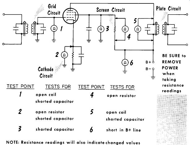
In the typical i-f amplifier circuit below are shown the ohmmeter check points. The plate circuit is checked by a value reading and continuity of the plate load. The screen circuit is checked by reading the value and continuity of the screen dropping resistor. The screen bypass capacitor is checked for a short circuit. The cathode circuit is checked by a simultaneous reading of both the cathode resistor and bypass capacitor. If the cathode capacitor is not shorted, the only reading in the cathode circuit should be that of the cathode resistor. The grid circuit is checked for continuity.
The B+ line is checked for a short circuit by taking an ohmmeter reading between B+ and B-. The reading should normally be high, in the order of 100,000 ohms or more; a low value reading of hundreds of ohms or less indicates a short circuit in the B+ line.
Screen Circuit
-----
TEST POINT TESTS FOR TEST POINT TESTS FOR 1 open coil 4 open resistor shorted capacitor 2 open resistor s open coil shorted capacitor shorted capacitor 3 shorted capacitor 6 short in B+ line NOTE: Resistance readings will also indicate changed values B+ Plate Circuit BE SURE to REMOVE POWER when taking resistance readings
Signal Injection
A dynamic method of servicing is by means of signal injection. A signal from a signal generator is used as a substitute. An audio signal is first injected in the audio power output stage of the receiver, and then worked towards the detector. Care must be taken not to overload the receiver.
This will check the audio circuits to the detector. From the detector to the converter a modulated i-f signal is used and a modulated r-f signal is used from the converter to the antenna.
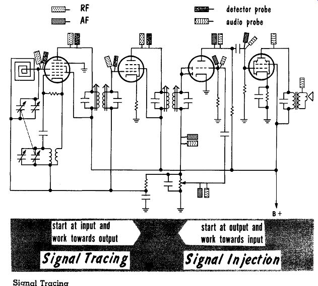
----------63 start at input and work towards output
Signal Tracing start at output and work towards input
Another dynamic method of servicing that has gained many adherents is signal tracing. A signal tracer, as the name implies, will trace the signal from input to output-the opposite direction of signal injection. From the antenna to the detector a special detector probe is used to trace the signal path. From the detector to the loudspeaker an audio pickup probe traces the signal path.
Signal tracing has an advantage in that it does not load the circuit and requires no special precaution in its use.
Isolation of Trouble
When a set is brought in for repairs the customer's complaint should be noted, and must be confirmed by the serviceman. This is especially important since the complaint can be misleading.
Prior to any troubleshooting a visual and audible test should be made. If the set has a cathode-ray tuning indicator (magic eye), a visual test can be made before the set is removed from the cabinet. With the set turned on, the indicator tube should turn green; if not it means there is no B+. If the indicator tube turns green, the tuning shadow should be checked. If the shadow remains open at the widest angle while tuning through the dial, it indicates a defect in circuits ahead of the detector. When the indicator tube shadow opens and closes while tuning through the dial but no output is heard, it indicates a defect in circuits after the detector.
Whether the receiver has a tuning indicator or not, a visual test must be made for obvious defects such as charred resistors, open filaments, a completely dead filament string in series-wired filament circuits, etc. In addition to the visual test a simple audible test should be made - listening to the receiver for hum, excessive noise, a noisy or intermittent volume control, etc. Since tubes are responsible for a large percentage of the defects, they should be tested before taking the next steps.
---
-----
Isolation of Trouble ( cont’d)
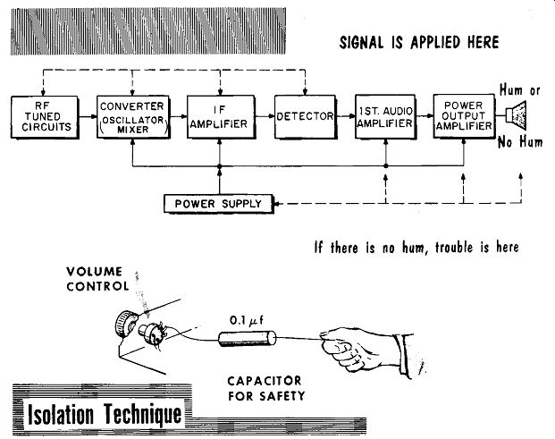
If there is no hum, trouble is here ...
A quick and effective method is to place a finger on the center tap or arm of the volume control of the receiver while it is on. There is no operating voltage at this point. If desired as a safety precaution, a coupling capacitor such as a 0.01-mfd capacitor can be held in the hand with the other end applied to the volume control arm or center tap. This applies enough induced 60-cycle signal to the grid of the first audio amplifier to produce a clear, audible 60-cycle hum in the speaker. If the hum is loud and distinct, two important portions of the receiver are quickly checked out: the power supply and the audio section. The defective stage, therefore, is the detector or a stage ahead of it. If no hum is heard in the speaker, it means that the audio circuits or the power supply is defective. In the latter case the power supply should be checked first since it is common to the entire receiver.
If the trouble is in or before the detector stage, a signal tracer can be applied from the r-f tuning circuit at the antenna toward the detector until the defective stage is reached. If the trouble is in the circuit after the detector, the power supply having been checked out, the signal tracer can be used with an audio probe to follow the signal from the detector load (volume control) towards the loudspeaker to locate the defective stage.
Isolation of Trouble ( cont’d)
Signal injection could also be used in a similar manner. If the troubles are before the detector stage, a modulated i-f signal can be applied to the detector to check it out. The injected signal can then be moved back to the grid of the i-f amplifier tube. To check the converter or mixer tube a modulated r-f signal of the same frequency to which the receiver is tuned can be injected to the r-f grid of the converter or mixer tube. If an r-f amplifier stage is used the same r-f signal can be moved to the grid of the r-f amplifier tube. When the trouble is after the detector, the audio output of the signal generator can be applied to the power output stage and then worked back to the detector load to determine the inoperative stage.
-------
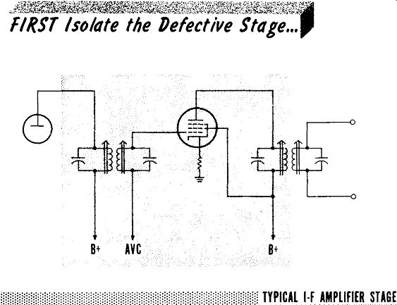
After locating the defective stage the next step is to isolate the defective circuit. Using as an example a typical i-f amplifier stage, see figure, it will be assumed that this is the defective stage. The next step is to determine the defective circuit within the stage. Using a signal tracer-if the signal is present at the grid but not at the plate, the difficulties are either in the tube or plate circuit. The plate circuit includes the cathode circuit, and the screen grid circuit or plate circuit. If the signal is present in the plate of the preceding stage but not at the grid of the i-f amplifier stage, the grid circuit is checked. The grid circuit includes the secondary of the i-f transformer, the AVC circuit, and the cathode circuit. Common to both circuits are the filament circuits.
The same procedure is used for signal injection. If the i-f signal injected at the grid is not heard at the loudspeaker, the plate circuit is checked. If the plate circuit checks out, the grid circuit has to be checked to find the cause of failure.
After the defect is isolated in the circuit, the next step is to isolate the defective part or parts. The voltages on all the tube elements are noted, including the filament voltage and the A VC voltage, if necessary. If the voltage readings are correct and the tube is good, the next step is to take resistance readings. In· taking resistance readings of the i-f transformer, the resistance of the windings should be carefully noted. A shorted capacitor will give a zero reading while the correct reading should be a few ohms.
If all resistance readings check out the last resort is part substitution. This extreme measure is taken when all the other methods fail. An example would be a ferrite-core i-f transformer in which the core has cracked. All measurements would indicate a good transformer: the only way to find this difficulty would be to substitute another i-f transformer.
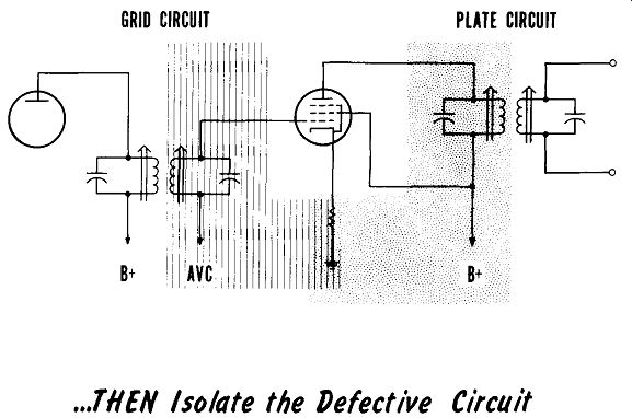
------- GRID CIRCUIT PLATE CIRCUIT
... THEN isolate the Defective Circuit
After the defective part or parts are replaced, the set should be checked for proper operation. Quite often, in addition to the defect that caused the set to cease operating, or to operate so that it could not be used, there are other minor defects that should be remedied. These include such things as open pilot lights, alignment and dial tracking, cleaning the dial, chassis and cabinet, high hum level due to inefficient filters, etc.
SUMMARY
Use the customer's complaints as a guide in locating receiver difficulties.
Note the complaints on a service tag; don't trust to memory.
An obvious first step in servicing a receiver is a sharp visual inspection.
An important servicing technique is to reason the difficulties. Knowing the circuit operation helps in reasoning the nature of the difficulty.
The four most popular methods of receiver servicing are by voltage readings, resistance readings, signal injection, and signal tracing.
A good first step is taking voltage readings. Checking power supply voltages is a quick step since these voltages are common to the entire receiver.
For absolute tube circuit voltages the readings should be taken with the negative lead of the voltmeter at the cathode of the tube. In actual practice the negative probe of the meter is usually clamped to a common point.
An important precaution when taking ohmmeter readings is to be sure the receiver is turned off and the a-c plug removed from the outlet.
Prior to troubleshooting a receiver, a visual check should be made for charred resistors, open tube filaments, leaking capacitors, etc.
If visual and audible checks have not located the difficulty, three steps should be taken: isolate the defective stage, isolate the defective circuit, and isolate the defective part or parts.
A quick method of isolating the stage is to place a finger on the center tap of the volume control. A resulting 60-cycle hum indicates the power supply and audio section are checked out and the defect is in or ahead of the detector. No hum will indicate either a defective power supply or defective audio amplifier circuit.
Signal tracing or injection can be used to isolate the defective stage.
After locating the defective stage, use signal tracing or injection to locate the defective circuit or portion of the circuit.
To isolate the defective component, voltage and/ or resistance readings are taken. If all readings check good a last resort is part substitution.
REVIEW QUESTIONS
1. What is the prime objective for servicing a receiver in the shortest possible time?
2. In addition to a visual inspection, what other testing senses are avail able? Describe how you would use them.
3. Do the four methods of servicing have to be used independently, or may they be combined?
4. How low can the voltage readings be before we should correct them, even if they are not the source of the trouble?
5. In servicing by signal injection, what precaution should be taken?
6. What are the advantages of servicing by signal tracing?
7. When a tuning eye indicator tube is available, describe what functions can be checked by the indicator tube.
8. What are some of the minor defects that may require remedying after a receiver has been restored to operation?