The preceding discussions were of a general nature-; no specific stages were discussed except as examples. Knowing the methods of isolating and eliminating the defect in general is not in itself sufficient; additional discussion of typical stages is also required. Each stage can be serviced methodically with the least wasted time by following the reasoning of cause and effect.
An example might be a power supply with low output voltage, resulting in a check for only the possible causes for this effect, and not the entire power supply. All the stages discussed will be vacuum tube operated, and a discussion of transistor-operated, radio receiver circuits will be found in a later chapter.
---------------- 
-------------
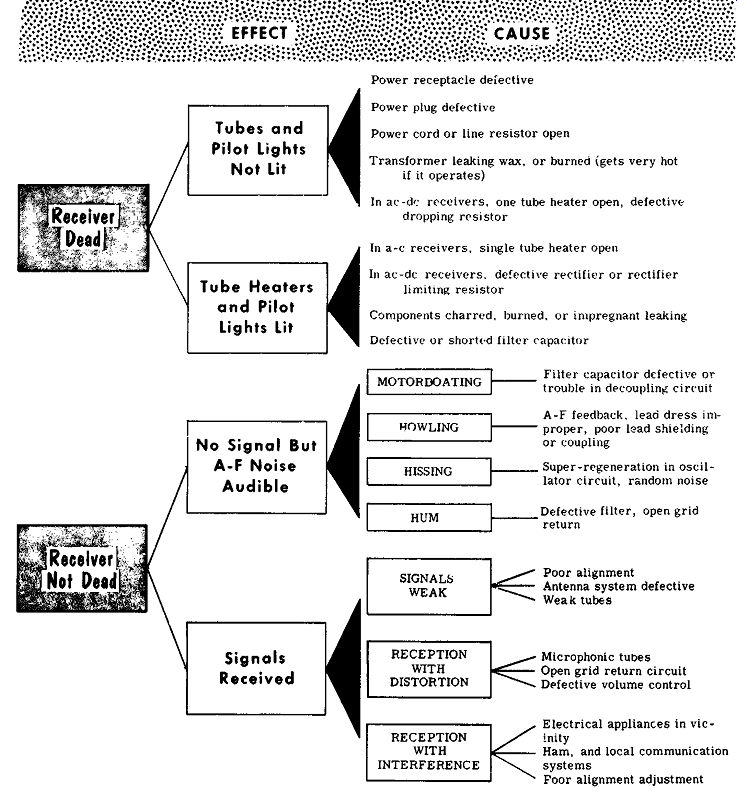
might be a power supply with low output voltage, resulting in Tubes and Pilot Lights Not Lit Tube Heaters and Pilot Lights Lit No Signal But A-F Noise Audible Signals Received Power receptacle defective Power plug defective Power cord or line resistor open Transformer leaking wax, or burned (gets very hot if it operates)
In ac-dc: receivers, one tube heater open, defective dropping resistor In a-c receivers. single tube heater open In ac-dc receivers. defective rectifier or rectifier limiting resistor Components charred, burned. or im-pregnant leaking
Defective or shorted filter Capacitor
Defective filter, open grid
~ return RECEPTION WITH DISTORTION RECEPTION WITH INTERFERENCE
Poor alignment . Antenna system defective Weak tubes Microphonic tubes Open grid return circuit Defective volume control Electrical appliances in vicinity Ham, and local communication systems Foor alignment adjustment
----------
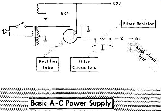
A-C Power Supply
---------------6.3V Rectifier Tube 6X4 Filter Capacitors
Resistor
----------------
A typical transformer-operated a-c power supply is illustrated above. With no B--1- output, a check is made of the a-c voltage to the primary winding. If this voltage is not present, the line cord, line plug, and switch are tested.
If the line voltage is present at the primary, test for high voltage ac to the rectifier plates. If the high voltage is not present, the primary and secondary windings should be tested for an open circuit. With high voltage ac at the plates of the rectifier, verify the center tap of the secondary winding by testing the a-c winding from the common to either rectifier plate. If there is no reading the difficulty can be the opening of the center tap lead to common.
If the previous checks are positive and there is still no a-c output, the trouble is either a defective rectifier tube, no filament voltage to the rectifier, a shorted input filter capacitor, or open filter resistor. A shorted output filter capacitor could remove B - from the output, but would permit a reading of voltage at the input filter capacitor.
To determine the cause of low B--'-- voltage, the circuit should be opened at the point indicated to remove the load at the output filter. If after doing this the B- voltage rises to normal, it indicates a short circuit in some other stage. If the B- voltage remains low. it indicates the difficulty is in the power supply, and the following tests can be made. Check the electrolytic capacitors for excessive leakage. Take an ohmmeter reading of the filter resistor for an increase in value. Replace the tube to check for low emission and verify that the correct a-c voltage is being applied to the rectifier plates.
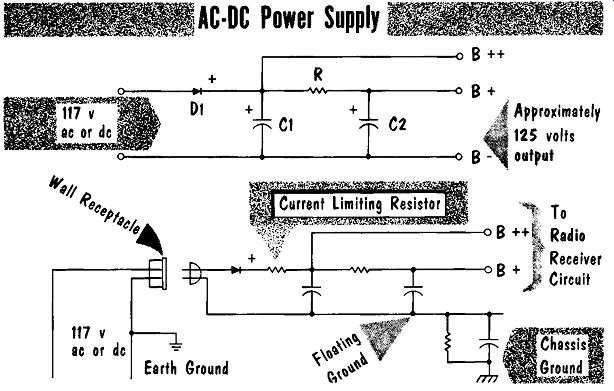
AC-DC Power Supply
A typical ac-dc power supply is shown. With an a-c line input, the circuit becomes a simple half-wave rectifier; with a d-c input, the anode of the diode must be connected to the positive side of the line. The diode then acts merely as a conductor, permitting the de to be applied directly to the circuits. The higher B · voltage at the input to the filter can be applied to circuits that do not require a completely ripple-free voltage. The rectifier you may encounter in actual practice may be a vacuum tube or a selenium or silicon diode rectifier.
-----------
The output voltage of an ac-dc power supply is dependent upon the line voltage. Assuming an a-c line voltage of 115 volts, the average output voltage under load will be from 125 to 135 volts. When used with a d-c line,
+ f Receiver ,) Circuit Earth Ground the receiver B-'- will be the value of the d-c line voltage. In most receivers using an ac-dc power supply, the common line is floating, and returned to the chassis through a capacitor and high value resistor. With no B+ output voltage check if ac is being applied to the anode (plate), and if de is at the cathode of the rectifier. If a-c voltage is present at the plate, but no d-c voltage is at the cathode, the rectifier should be checked. If the rectifier checks good, test for short-circuited filter capacitors or an open filter resistor.
With low B- the load to the power supply should be lifted at both filters.
If the output voltage stays low, the following tests should be made: check the electrolytic capacitors for excessive leakage; take an ohmmeter reading of the filter resistor for an increase in value; and replace the rectifier to check for low emission
A typical half-wave rectifier circuit with tube layout is shown. An open filament in the series filament circuit is perhaps the most common difficulty.
The surge of line current through the tubes when they are cold will often open a filament, particularly in the higher voltage filaments of the rectifier
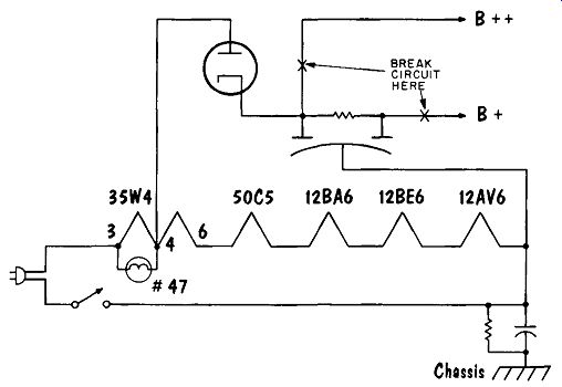
---------- -- HALF-WAVE RECTIFIER CIRCUIT
....and power output tubes. To check for an open filament, the ohmmeter probes are placed across the line cord plug with the switch turned on.
If an open circuit is indicated, the individual tubes can be removed one at a time for a continuity test of the filaments. The first tube tested should be the rectifier. Often the pilot light will have opened and not been replaced, causing the current that should have been flowing through the pilot light to flow through the portion of the filament that develops the pilot-light voltage drop. In time the excess current causes the filament to open be tween pins 3 and 4. Another possibility is that a short circuit in the receiver will cause excessive current flow through the rectifier tube and this portion of the filament. The next probable open filament is the power output tube due to its high filament voltage. Following the power output tube the tubes can be tested in any order. On occasion the difficulty may be an open line cord, defective a-c line cord plug, or an open switch.
Audio Power Output Stage
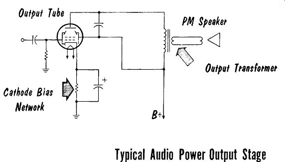
A typical, one tube (single ended), audio power output stage is illustrated.
One of the more common ailments of this stage is distortion caused by a leaky coupling capacitor placing a positive voltage on the grid. A gassy (soft) tube will also cause distortion. The power output tube in ac-dc receivers is prone to develop a heater-to-cathode leakage, possibly due to the high filament voltage used. This leakage places 60 cycles in the plate circuit causing an annoying 60-cycle hum similar to that caused by defective filter capacitors.
A test speaker is often available in the shop to substitute for a questionable speaker or to save the trouble of having to remove the speaker from a cabinet. A good quality substitute speaker should be used since it may have to check out high-power output receivers as well as small receivers.
---------
Typical Audio Power Output Stage
With no audio output the first step is to check the plate, screen, and cathode voltages. If all voltages are correct, listen carefully to the speaker.
If there is some hum or a slight bit of noise, it indicates the speaker is operating and the troubles are probably before the speaker. If there is no hum or noise then the speaker should be tested. If the speaker checks good then the output transformer should be checked for an open secondary winding. An open primary winding would have been disclosed in a check of the plate voltage, and would cause high screen grid current. After the output transformer is replaced, check the tube carefully to be sure it has not been damaged,
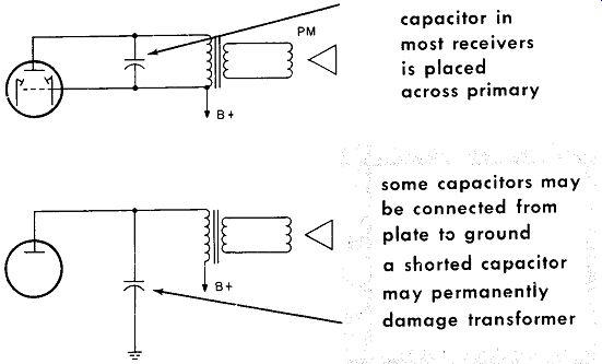
The majority of receivers use a capacitor across the primary of the output transformer. In some receivers the capacitor is placed from plate to ground.
Should this capacitor short circuit, it would draw excessive current through the primary of the output transformer, probably damaging it. If the capacitor is defective it should be replaced with a 600-working-volts-rating capacitor.
A defective tube could also cause the loss of an audio output signal. An open cathode-bias resistor would have been disclosed in the check of voltages. An open grid-return resistor would block the tube and cut off any output signal.
An open coupling capacitor is another possibility in testing for a lack of audio output signal.
Do not overlook any radio-phonograph switch that has inadvertently been placed in the phonograph position, cutting off the radio signal.
A distorted output signal can be caused by a warped voice coil, causing it to rub against the pole piece. Other causes of distortion could be a leaky or
-----------
... capacitor in most receivers is placed across primary some capacitors may be connected from plate to ground a shorted capacitor may permanently damage transformer
-------------------
... open tone-control capacitor, a gassy (soft) tube, a shorted coupling capacitor. A 60-cycle hum is often caused by a cathode-to-heater leakage in the tube.
Low output can be caused by a tube with low emission. Another cause could be an open, cathode bypass capacitor causing degeneration. Degeneration will aid the fidelity of the signal at the expense of the amplitude. Low B+ would have been disclosed with the check of plate and screen voltages.
On rare occasions shorted turns in the output transformer could also cause a reduced output signal.
--------
Push-Pull Power Output Stage
PHASE INVERTER COMMON BIAS NETWORK PM SPEAKER B+
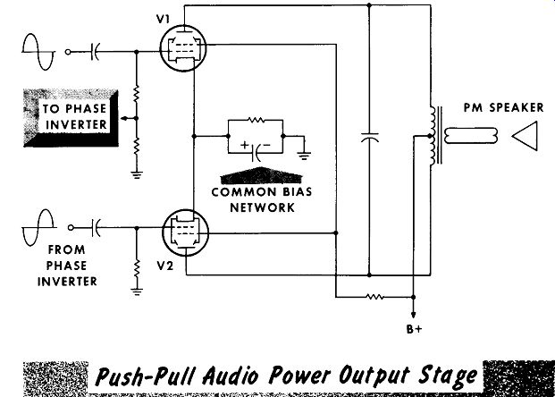
Push-Pull Audio Power Output Stage
A typical push-pull power-output audio amplifier is shown. The problems of a push-pull audio amplifier are similar to those of a single-ended amplifier with the addition of the special problems brought on by push-pull operation. The more common difficulties are leaky coupling capacitors, defective tubes, and speakers.
As in the single-ended amplifier with no audio output, the first step is to check out the plate, screen, and cathode voltages. With all voltages correct, listen carefully to the speaker-any audible hum or noise means that the speaker is operating and the troubles are before the speaker. If no hum or noise can be heard, the speaker voice coil should be tested for an open circuit. If the speaker voice coil tests good, then the output transformer should be tested for an open secondary winding. Should the capacitor across the primary short out, it would remove the plate load, and there would be no output. An open coupling capacitor to tube V1 would result in no signal to V1, and the phase inverter. In turn V2 would also have no signal input.
An open cathode bias resistor would have shown up in checking the cathode voltage.
Push-pull audio circuits are in more common use in radio-phonograph combination receivers. It is important that the radio-phonograph switch be examined to be sure that it has not been set to the phonograph position, cutting off the radio signal.
Distortion in the output signal can be caused by a warped voice coil. Other causes of distortion could be that the capacitor across the output trans former primary is leaky or open. A gassy tube, a shorted coupling capacitor, a cathode resistor that has increased in value, or a shorted, cathode bypass capacitor can also cause distortion. A 60-cycle hum could be introduced by heater-to-cathode leakage in a tube.
If one output tube becomes defective, the other tube will still provide an output. With only one tube operating the reduced plate current would result in reduced cathode bias. The improper value of bias could cause distortion. Any difficulty causing a difference in gain between the phase inverter amplifier and the first audio amplifier could supply unequal values of signal to V1 and V2, causing distortion. Waveforms for Class A operation (plate current present during entire cycle of input for each tube) are shown in the illustration.
Low-value audio output could be caused by one tube or both tubes having low emission. An open cathode bypass capacitor could cause degeneration and reduce the output. Reduced values of plate or screen voltage would have been disclosed with the voltage check. Occasionally, shorted turns in the output transformer could also cause a reduced output signal. An open circuit in one-half of the primary would have shown up in a check of the plate voltages. A defective tube with no output would result in low output since the other tube will still operate and provide a reduced output signal.
-------------------76
Audio Amplifiers
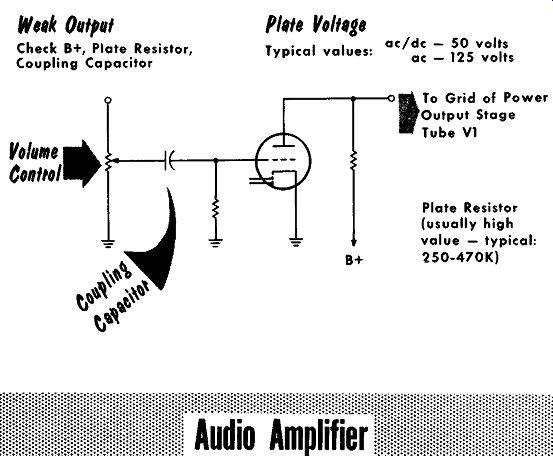
A typical audio amplifier stage is shown. The tube used is usually the high mu triode section of a duo-diode, high-mu triode tube. The cathode is at ground since it is common to both the detector stage and the first audio amplifier stage. The low value of input signal received from the detector
output requires a high-mu triode. A high-value, grid-return resistor of 5 to 10 megohms is used to develop contact bias. The high impedance grid input circuit makes it "hot" and prone to hum pick-up. This is especially true in radio-phonograph combinations where a long phonograph pick-up lead may be used. To keep hum to a minimum, shielded cable is used for the phonograph lead.
-------- 77
Weak Output
Check B+, Plate Resistor, Coupling Capacitor Plate Voltage ac/dc - 50 volts Typical values: ac _ 125 volts B+ t To Grid of Power Output Stage Tube V1 Plate Resistor (usually high value - typical: '250-470K)
If there is no audio output of the first audio amplifier stage, the plate voltage should be checked. An open plate-load resistor would show up in this check. If the plate voltage and plate-load resistor check out, a good tube should be substituted. An open grid resistor could block the tube, resulting in no output. The same result would occur with an open coupling capacitor to the grid. A defective wiping-arm contact on the volume control potentiometer could remove the input signal to the amplifier. An open potentiometer (a defect in the detector circuit), would also result in no signal to the amplifier tube.
Phase Inverters
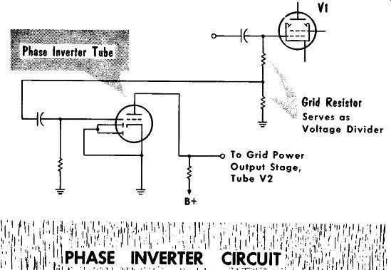
A typical phase-inverter stage is shown below. To achieve an equal but opposite signal an exact duplicate of the first audio-amplifier stage is most often used. The input signal is taken from a signal voltage divider in the grid of V1, one-half of the push-pull power-output stage. The problems in the phase-inverter stage are identical with those of the first audio-amplifier stage. The only difference is the possible loss of the input signal due to an open grid resistor in the grid circuit of V1.
To have the push-pull amplifier work effectively, the outputs from the audio amplifier and the phase inverter should both be approximately equal. If the value of the grid resistor of V1 should change, it may result in one output ...
---------
Grid Resistor
Serves as Voltage Divider
To Grid Power Output Stage, Tube V2 B+
... being greater than the other; an undesirable effect. However, this change would be over the entire resistor, hence the voltage divider ratio would remain the same, and not affect the output. The resistor tap may not necessarily equal half the total value of the grid resistance since the gain of the tubes may not be equal; the difference in gain is compensated by the voltage divider network. A good test would be to check the outputs of the audio amplifier and phase inverter; they should be approximately equal.
However, because the gain of the tubes may not be equal, a slight difference in the outputs can be expected and tolerated. If there is a large difference, then the tubes are likely suspects.
Detector Stage
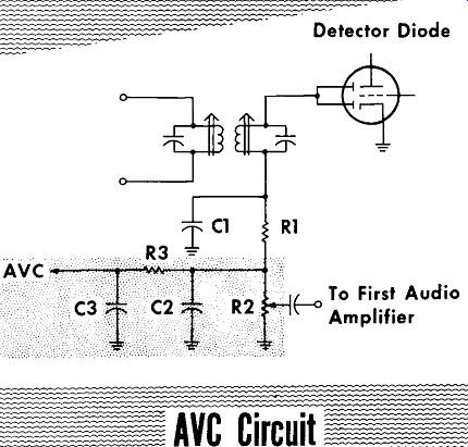
The detector circuit shown below operates with signal voltages and currents, making it relatively trouble-free. The tube used is usually the diode portion of a duo-diode, high-mu triode tube. Perhaps the most prevalent trouble is due to misalignment. To check for misalignment the intermediate frequency should be injected with a signal generator at the grid of the preceding i-f amplifier stage. The output frequency of the signal generator should then be varied above and below the intermediate frequency until an output signal is heard. If the output is above or below the correct frequency, the stage should be realigned.
In many detector circuits the filtering provided by R1 and C1 is omitted, with R2 and C2 providing all the filtering. The volume control is the only component of the circuit to receive any wear, and occasionally it will open.
With the receiver tuned to a local station, there should be a voltage developed across the detector load. This signal can be checked with a VTVM, a cathode ray oscilloscope, or signal tracer. Loss of output voltage could be caused by misalignment as previously discussed, or an open secondary winding of the i-f transformer. The detector load, R2, or filter resistor, R1, could open to cause the loss of signal. The possibility of a defective tube must also be checked, keeping in mind that the tube may operate correctly as an audio amplifier and still be defective as a diode detector. A broken ferrite core or a shorted trimmer in the i-f transformer could also cause a signal loss.
-----------
AVC Circuit
Atmospheric conditions may cause fading of signals coming from certain stations. The resulting output of the receiver may, at one moment, be loud enough to blast the listener from his seat, while it may fade during the next moment to the point of becoming inaudible. With A VC this is prevented.
The most frequently encountered A VC circuit is incorporated in the diode detector stage. Resistor RZ is the A VC load resistor and also the diode load.
The A VC bias voltage is developed through the additional filtering of R3 and C3. With the low currents and voltages developed, these components give very little trouble. To check the A VC voltage a VTVM should be used to prevent loading the circuit. Should the filter capacitor become leaky or open, it would reduce the A VC bias voltage. The reduced bias will cause the set to act as though there is no A VC. For weak stations the volume will have to be turned up and for strong stations 'the volume will have to be reduced. On strong local stations the reduced bias will cause the tube to overload and distort.
Should filter resistor R3 open there would be no output since the grid return of the i-f and r-f stage is through A VC line. With no grid return the i-f and r-f amplifier tubes would block and pass no signal. The open grid circuit may also cause 60-cycle-hum pickup.
I-F Amplifier Stage
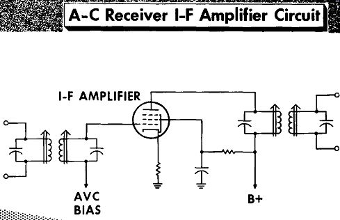
A typical i-f amplifier stage as used in ac-dc receivers is shown in the figure.
The cathode bias resistor is a precaution - with no signal there will be no A VC bias developed, the grid will be at zero potential, and the tube will draw heavy plate current. The cathode bias resistor provides a small amount of bias to limit the plate current flow under no-signal conditions.
As in the detector stage a common difficulty is misalignment. To check this the intermediate frequency should be injected with a signal generator at the r-f grid of the converter tube. The output frequency of the signal generator should be varied above and below the intermediate frequency until an out put signal is heard. If the output is above or below the correct frequency, the stage should be realigned.
------------81
I-F AMPLIFIER AVC BIAS ; B+
With no output from the i-f amplifier stage, the plate, screen, and cathode voltages (where a cathode resistor is used) should be checked. An open primary winding in the output i-f transformer would show up on the check of the plate voltage. An open cathode resistor would also cause the loss of a signal. A defective tube should be checked by inserting a substitute. To check for an open secondary winding of the input i-f transformer, check for presence of the bias voltage between grid and cathode or check with an ohmmeter continuity test. Another possibility for loss of signal is a shorted, i-f transformer trimmer capacitor, or a broken ferrite core.
Receivers with transformer-operated power supplies will most often have the i-f amplifier-tube screen-grid operate at a lower voltage than the plate.
For this a voltage-dropping resistor is placed in series with the screen grid and a by pass capacitor is placed at the screen grid. The screen resistor can open or the screen bypass capacitor can short, removing the screen voltage.
----------- A-C Receiver I-F Amplifier Circuit
AVC BIAS J B+
When the bypass capacitor has shorted, be sure to check the screen resistor-- it may have changed value due to the excess current flow through it caused by the shorted capacitor.
A reduced output signal can be a result of the cathode bias resistor changing value. Another reason could be a crack in the ferrite core causing a reduction in the Q of the i-f transformer tuned circuit. A low emission tube can also cause a reduction in the signal output. Reduced screen voltage because of an increase in the value of the screen grid resistor will have shown up in the voltage check. In receivers using transformer-operated power supplies with a screen dropping resistor and screen bypass capacitor, an open bypass capacitor would cause the screen resistor to act as a screen load. A signal will be developed at the screen grid that might cause feed back and oscillations.
Converter Stage
The converter stage is a multi-purpose stage that serves many functions.
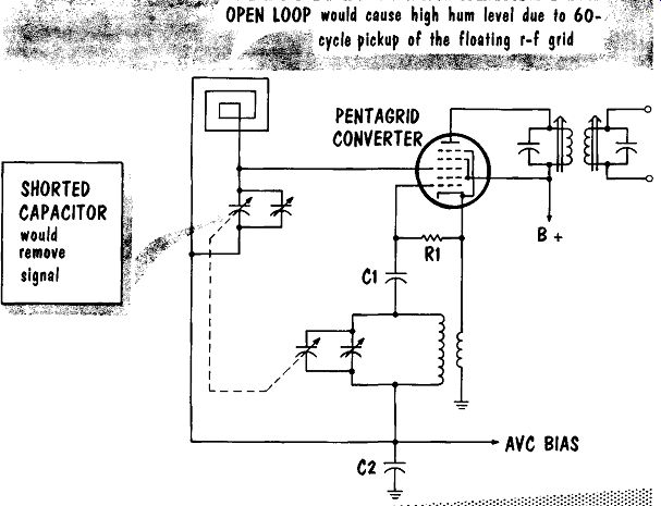
The r-f tuned circuits select the desired signal, the oscillator portion provides a locally-generated signal, and the tube mixes the two signals and develops the intermediate frequency in the plate circuit. The oscillator grid-leak bias is developed by R1 and C1; this is a convenient check point.
The voltage at the oscillator grid should be approximately minus 5 volts or more if the oscillator is operating. No grid-bias voltage is a sign that the oscillator is inoperative. The A VC filter capacitor, C2, acts as the a-c signal ground-return path for both the oscillator and r-f tuned circuits.
An aged pentagrid converter tube can get fussy - it may not oscillate over the entire range. When tested with a tube tester it may still check satisfactory. The proper test for such a tube to replace it with a good tube.
Another common difficulty with the pentagrid converter is cathode-to heater leakage causing 60-cycle hum.
---
SHORTED CAPACITOR would remove signal
PENTAGRID CONVERTER
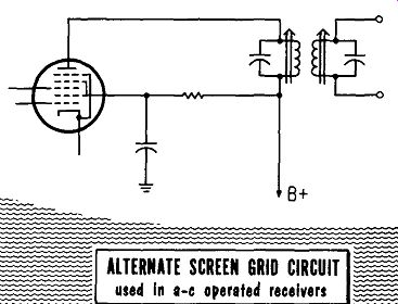
In many receivers a voltage-dropping resistor reduces the screen grid voltage. A bypass capacitor is used at the screen grid to prevent the voltage dropping resistor from acting as a screen load.
B+ ALTERNATE SCREEN GRID CIRCUIT used
----------
With no output signal the first step is to check the plate, screen, and oscillator-grid voltages. An open primary winding in the i-f transformer will show up in the plate voltage check. Another difficulty that could be caused by the i-f transformer is a shorted trimmer capacitor or a broken ferrite core. As mentioned previously, when the tube is suspect it should be replaced with a good tube. A check of the screen voltage would disclose an open screen-voltage-dropping resistor or a shorted screen-bypass capacitor.
When the voltage check indicates plate and screen voltages are present in the proper values but there is no voltage at the oscillator grid, it indicates that no oscillations are taking place. The first thing to test is the tube by replacing it with a good tube. The oscillator coil primary and secondary should be checked with an ohmmeter for continuity. Should the oscillator coil be defective, it is best to replace it with a direct substitute. This will prevent any difficulty in having the r-f and oscillator circuits track each other during the alignment procedure.
Another possibility for lack of oscillation could be a short circuit in the oscillator tuning capacitor or in its associated trimmer capacitor. On rare occasions resistor R1 will open or capacitor C1 will open or short. Should the A VC filter capacitor, C2, open, the a-c signal ground-return path would be a high impedance, and could also cause the oscillator to cease functioning.
R-F Amplifier Stage
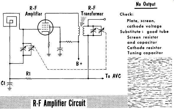
Very little trouble is encountered in r-f amplifier stages. Occasionally a loop antenna will open or the tuning capacitor will short circuit. A small amount of cathode bias is developed as a precaution. With no signal there will be no A VC bias developed, the control grid will be at zero potential, and the tube will draw heavy plate current. The small amount of cathode bias limits the plate current flow under no-signal conditions.
Because of the added number of stages and the possibility of feedback between the stages, an additional decoupling filter, R1 and C1, is used in the A VC circuit.
Should capacitor C1 of the A VC decoupling filter short, there would be no bias at the control grid of the amplifier tube. With no bias the tube would operate at full gain, and, on strong local signals, the tube would overload
-----------
R-F Amplifier
No Output Check: Plate, screen, cathode voltage Substitute : good tube Screen resistor and capacitor Cathode resistor
Tuning capacitor and cause distortion. An open antenna loop would leave the control grid floating to pick up a 60-cycle hum. Should resistor R1 open, the grid return path would be open, and the grid would be floating and pick up a 60-cycle hum.
Reduced output of the r-f amplifier stage could be due to a reduced value of B + voltage, or a low emission tube. Should the cathode bias resistor increase in value it will reduce the output signal. An open screen bypass capacitor would cause the screen resistor to act as a screen load. A signal will be developed at the screen grid that might cause feedback and oscillation. An increase in the value of the screen dropping resistor would reduce the screen voltage in turn reducing the gain of the stage.
Alignment of Superheterodynes
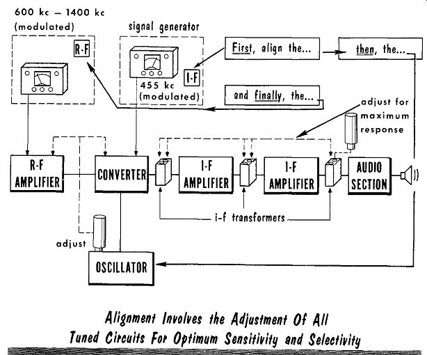
There are many tuned circuits, operating at different frequencies, in a superheterodyne receiver A major point in maintenance and proper operation is that they all be tuned to the proper frequencies; this is known as alignment.
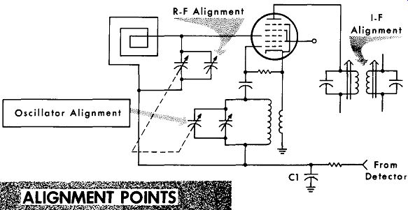
There are three tuned circuits or sets of tuned circuits that must be adjusted-- the i-f amplifier, the local oscillator, and the tuned r-f amplifier. These circuits should be adjusted in the order given. To align the i-f amplifier circuits, the local oscillator and A VC circuit must be made inoperative.
Oscillator Alignment
--------
The simplest method to disable the oscillator is to place a small length of solder across the oscillator stator plates, then turn the rotor plates all the way out till they rest firmly against the length of solder, which will short the oscillator variable capacitor and disable the oscillator.
To disable the A VC the bias across the A VC filter capacitor, C1, should be shorted to common. With the local oscillator and A VC bias voltage disabled, the modulated output of the r-f signal generator is coupled through a 0.01 mfd capacitor to the r-f grid of the converter. This is easily accessible at the r-f section of the variable tuning capacitor - the lug on the side of the variable tuning capacitor is connected to the stator plates. The stator plates are directly connected to the r-f grid of the converter tube.
The output frequency of the r-f signal generator is carefully set to the correct value of the intermediate frequency as noted by markings on the transformer or printed on the schematic diagram of the receiver. It is important that this value be correct, otherwise the circuit will not tune and may inadvertently be seriously detuned. The modulation signal should then be heard in the speaker output. Although the variations in output can be heard by ear, an output meter is more reliable since it will register small inaudible variations. The output meter, an a-c voltmeter, is placed across the speaker voice coil.
-----
With the receiver volume control turned up to full gain, the output of the r-f signal generator is set for a reasonable meter indication. Using an insulated alignment tool, the output i-f transformer primary and secondary circuits are tuned for maximum gain as indicated on the output meter. The next step is to align the input i-f transformer primary and secondary circuits. If two stages of i-f amplification are being used, the interstage i-f transformer is followed by the input i-f transformer. Should the output greatly increase during alignment, the output of the r-f signal generator should be reduced. When all the i-f transformers are aligned, it is good policy to provide a final check by repeating the procedure.
Should the i-f transformers have been tampered with, the preceding procedure will be slightly changed: The output of the signal generator is coupled to the grid of the i-f amplifier, and the output i-f transformer primary and secondary circuits are aligned. The output of the r-f signal generator is then coupled to the r-f grid of the converter tube, and the input i-f transformer is aligned. After the i-f transformers have been aligned, the procedure should be repeated.
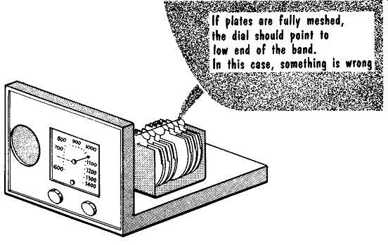
To align the oscillator the small length of solder used to short the oscillator tuning capacitor must be removed. The next step is very important: Check the dial pointer to be sure it is set properly. To do this set the variable tuning capacitor all the way in for maximum capacity. This should set the dial pointer at the extreme low end of the calibration. Then turn the variable tuning capacitor all the way out for minimum capacity. This should set the dial pointer to the extreme high end of the calibration. If the dial pointer is off it should carefully be reset before proceeding. Some receivers have the dial markings on a glass or clear plastic plate mounted on the cabinet. This may necessitate sliding the receivers in and out of the cabinet to check the pointer. Some receivers have markings on the background plate used to set the pointer with the receiver out of the cabinet.
With the pointer accurately set, the next step is to remove the r-f signal generator output from the r-f grid of the converter tube, and couple a signal to the antenna coil. The signal is coupled to the antenna binding post through a 200-mmfd coupling capacitor. When a loop antenna is used, merely placing the output lead of the r-f signal generator on or near the loop without making a direct electrical connection will induce sufficient signal voltage in the loop antenna. Set the modulated output of the r-f signal generator to a frequency of 1400 khz and set the dial pointer to 1400 khz.
If the oscillator is correctly set, it should beat with the r-£ signal, and produce a signal at the value of the i-f tuned circuits. Adjust the trimmer of the oscillator section of the variable tuning capacitor for maximum output.
-------
Quite often the r-f signal generator being used may not be accurate. To check both the oscillator setting and the r-f signal generator, a station at a known frequency should be tuned in. If the oscillator trimmer and dial pointer are correctly set, the station should be at the correct position on the pointer. At times the oscillator frequency is so far off that the i-f beat frequency comes in at some other point on the dial, perhaps 1450 khz while at the correct frequency of 1400 khz no signal is heard. When this happens the dial pointer can be set to a slightly lower frequency, say 1440 khz where the beat can still be heard. At this frequency the trimmer should be set for maximum. The dial is then slowly moved down step by step 1430 khz 1420 khz etc., until it is finally at the correct position of 1400 khz.
------
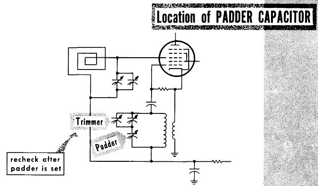
When the oscillator circuit contains a padder capacitor, the padder capacitor is adjusted at a low frequency, say 600 khz. The modulated output of the r-f signal generator is set to 600 khz and the padder capacitor adjusted for maximum output. While adjusting the padder, the variable tuning capacitor is gently rocked back and forth to be sure that the padder is set at the proper point on the dial. After the padder is set it is good practice to recheck the trimmer at 1400 khz. With the output of the r-f signal generator set at 1400 khz and the receiver tuned, to 1400 khz the trimmer of the r-f section of the variable tuning capacitor is adjusted for maximum output.
SUMMARY
In a typical a-c power supply with no B-plus output, first test for a-c voltages of the power transformer's primary and secondary. Also test the rectifier tube, filter capacitors, and filter resistor.
In an ac-dc power supply, the most common difficulty is an open filament in the series filament circuit. In testing for an open filament, the first tube tested should be the rectifier, the next tube the power output amplifier, and the remaining tubes in any order.
With an a-c line voltage of 115 volts, the average output voltage of an ac-dc power supply under load is from 125 to 135 volts.
In an audio power output stage, a leaky grid coupling capacitor, a gassy tube, or heater-to-cathode leakage are common difficulties.
When replacing a defective capacitor from the plate of the output tube to ground, use a replacement with a 600 working volts rating.
If one tube of a push-pull amplifier becomes defective, the remaining tube will still provide an output, though it may be reduced and distorted.
The detector circuit operates with signal voltages and currents-it is relatively trouble-free with the major problem being output i-f trans former misalignment.
A common trouble in the i-f amplifier stage is misalignment.
In converter stages, a tube with reduced emission may test satisfactorily though the tube may not oscillate over the entire tuning range, or it may oscillate intermittently. Another cause of a loss, or intermittent oscillation, is shorted plates in the tuning capacitor.
R-f amplifier stages are relatively trouble-free, with an open loop antenna or shorted tuning capacitor being the major problems.
In aligning the tuned circuits of the i-f amplifier, local oscillator, and r-f amplifier should be adjusted in that order.
During alignment of the i-f amplifier tuned circuits, the local oscillator and A VC circuits are made inoperative.
REVIEW QUESTIONS
1. In testing power supply electrolytic capacitors for excessive leakage, what would be a typically correct reading on the ohmmeter?
2. In an ac-dc receiver, what is the method of checking at one time the entire series string of tubes?
3. What important fact must be kept in mind when using a substitute speaker to test high-fidelity audio amplifier circuits?
4. Explain the necessity for reading the A VC voltage with a VTVM.
5. What is the purpose of the small value cathode bias resistor often found in i-f amplifier stages?
6. Explain the necessity of an additional A VC bias decoupling filter at the grid of the r-f amplifier stage.
7. Describe a simple method of disabling the local oscillator for alignment of the i-f circuits.
8. What is the important reason for using an output meter for alignment?
9. At what frequency do we adjust the padder capacitor? The trimmer capacitor?