With the exception of the power supply, the stages used in a portable superheterodyne radio are identical to those in a table or console model radio. To service a portable receiver the same steps are used to isolate the troublesome stage and defective component. In using test probes the probe may slip and short together two tube-socket lugs, burning out a tube. For example, the probe placed on pin #2 of a type 1R5 tube may slip and short the pin to pin # 1, the filament connection, resulting in applied plate voltage to the filament. Applying tape, or in any manner covering the probe, and leaving uncovered approximately %-inch of the extreme tip to make electrical contact, is a precaution against shorting.
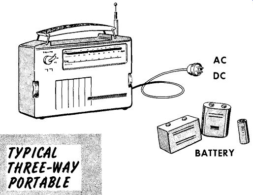
AC DC

-----
The tubes used in portable radios have 1.4-volt or 2.8-volt center tapped, directly-heated filament cathodes that operate on dc. When filament voltage is applied, there is no warm up time, resulting in instant tube operation.
The main difference between a normal radio and a portable radio, besides the tubes used, is the power supply. Some portables are operated by batteries only, and others have a combination power supply that operates on ac, dc, or batteries -- "three-way" portables.
Battery Operated Portables
One of the defects common to battery operated portables radios is weak batteries. When checking batteries it is best to use one of the special battery testers available. These will check a battery under load, and have a good-fair-bad meter scale. Actually seeing this reading on the meter is more impressive to a customer than taking the serviceman's word for the battery condition as read on a voltmeter. Labeling batteries with the store's name and date of purchase will protect the customer from purchasing weak batteries, and protect the store from receiving defective batteries in exchange for new ones under the guise that they were defective upon purchase. If no battery tester or substitute battery is available, batteries can be checked under load by leaving them plugged in to the receiver. With the receiver turned on, a voltmeter check of the battery voltage will determine whether or not it is run down. Over a 10 per cent reduction in the rated voltage indicates a weak battery.
When testing for open tube filaments be sure to use an ohmmeter that does not use more than a single cell in the ohmmeter circuit. When using a tube tester be very careful to set it for correct filament voltage.
The converter tube used in most battery-operated receivers, the type 1R5, is fussy, particularly in regard to the filament and or B+ voltage. Usually all the other stages will work but not the converter, although the tube checks good on a tube tester.
If the filament and or B+ voltage is a little low, the tube may not operate.
If the tube is old and its emission has dropped off, it may become intermittent. The best test of a questionable type 1R5 tube is replacement with a good duplicate.
Portable receivers are subject to considerable rough handling, which often leads to open filaments, and mechanical defects such as broken cases, open loop antenna leads, etc. A typical complaint is distortion caused by sand from the local beach settling between the voice coil and pole piece of the speaker.

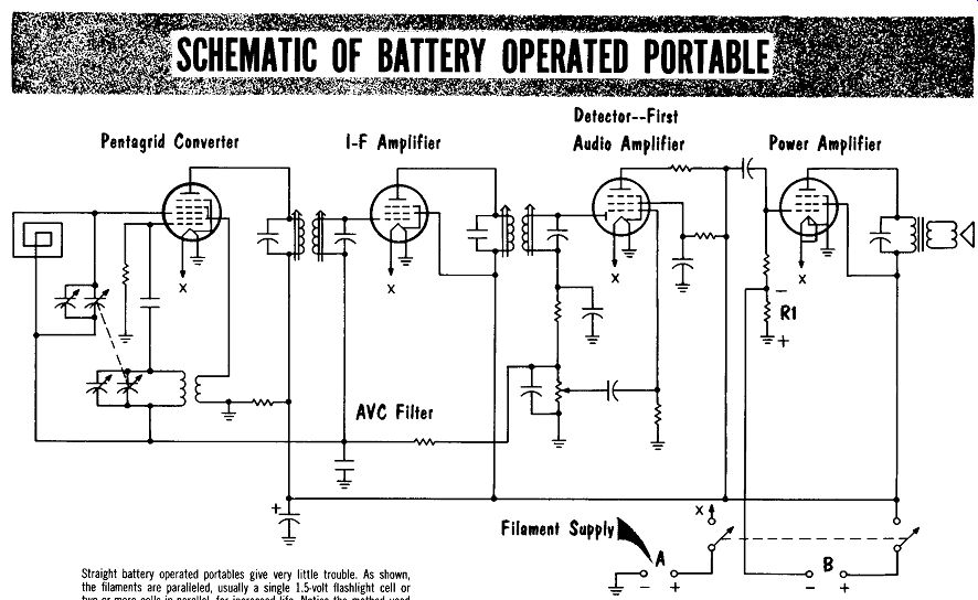
--- SCHEMATIC OF BATTERY OPERATED PORTABLE"
Pentagrid Converter I-F Amplifier
Detector--First Audio Amplifier Power Amplifier
Straight battery operated portables give very little trouble. As shown, the filaments are paralleled, usually a single 1.5-volt flashlight cell or two or more cells in parallel, for increased life. Notice the method used to obtain bias for the power output stage. The current flow through RI will provide a voltage drop with the polarities as shown. The grid return resistor is tied to the negative end of RI to provide bias for the power output tube.
Battery, AC-DC (Three-Way) Portables
The d-c voltage for the filaments is obtained either from batteries, or the d-c output of the rectifier. A series resistor is used to drop the voltage to the required value for the series wired filaments. Any sudden surge in line voltage would cause a slight increase in voltage to the filaments, and the increase will be distributed among all the filaments. Because of this no one filament will have too large a value of filament voltage, preventing excessive filament burnouts.
A precautionary measure before servicing a three-way portable receiver is to test the filaments of each tube. Filament burnouts are a common failure, and it is possible to have a whole series of filaments open up. An example might be forcing a battery plug into the battery socket so as to put B+ on the filament series. When a set is brought in for repair it is best to check the filaments first to forestall any possible claims by a customer that the filament burnouts were caused by the serviceman.
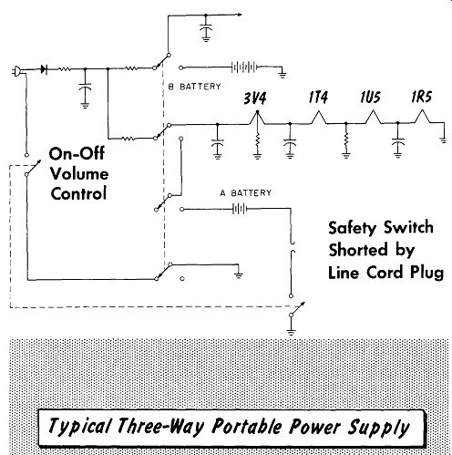
Basic 3-Way Portable Power Supply
With directly-heated filament cathodes, plate current for each tube would normally flow through the ground end of the filament string and through each filament to the cathode concerned. To prevent excessive cathode current from flowing through some of the tube filaments, shunt resistors are used. These resistors perform two functions - they act as cathode bias resistors and they distribute the current flow through multiple paths.
Should a shunt resistor require replacement, use a 10% or better tolerance resistor since to a large degree it determines the amount of current flowing in the filament circuit.
With the set switched to battery operation and performing satisfactorily, but not performing at all on line current, it is a safe assumption that the defect is in the power supply stage.
A three-way portable receiver will have two switches in the power supply circuit. One is used to switch from battery to a-c line operation, and the other is a special switch used as a precaution to prevent one from plugging the line cord into an a-c receptacle while the receiver is battery operated.
The two switches are often mechanically combined in the rear of the chassis by a device that automatically switches the receiver to battery operation upon plugging the line cord plug into a special receptacle. The receiver cannot operate on batteries unless this is done.
The possible defects in a three-way, portable-radio power supply with no voltage output and a-c at the rectifier, include an open rectifier, an open surge-limiting resistor, or an open filter resistor. Should either filter capacitor short, there would be no B plus. A defective changeover switch would also cause a loss of B-plus voltage. In battery operation a loss of B plus could be caused by an open changeover switch, or a shorted filter capacitor.
Reduced B-plus voltage could be the result of a defective rectifier, or an increase in the value of the surge limiting resistor, or the filter resistor.
High leakage in either the input or output filter capacitor could also cause a reduction in B-plus voltage. A shorted 40-mfd-filament filter capacitor could cause a high current drain to lower the B-plus voltage.
Filament string problems can be difficult to trace since the possibility of opening a tube filament inadvertently always exists. It would be best to check this circuit with the tubes removed and using ohmmeter readings.
An open shunt resistor, or one that has increased in value, will cause an increase in current causing a quick filament burnout. This problem is present in either the ac-dc or battery-operate position. Occasionally the added current will burn out the filaments over a period of time, showing up by recurrent filament opening of specific tubes.
A reduced resistance in the series voltage-dropping resistor of the filament circuit will permit increased current to flow in the filament string.
Depending upon the value of increased current the filaments will open up in time. An increased resistance will cause a reduction in the filament current flow, resulting in reduced filament voltages which in turn causes intermittent or no operation of the receiver.
Should the 0.1-mfd or the 100-mfd, low-voltage filament-circuit capacitor become leaky, it would draw excessive current causing the opening of tube filaments. This will occur in either the ac-dc or battery-operate position.
In battery operation an open change-over switch, safety switch, or on-off switch could cause the loss of filament voltage. To keep the drain on the supply batteries down to a minimum, the filaments are designed to draw only the lowest power necessary for proper tube operation. Since the transfer of heat to an indirectly heated cathode involves much greater energy losses than when the filament is itself the cathode of the tube, battery types, in which filament power must be a minimum, generally never have a separately heated cathode.

-------
On-Off Volume Control
Safety Switch Shorted by Line Cord Plug
Typical Three-Way Portable Power Supply:
In some three-way portables, the tuning capacitors are prevented from touching the chassis (a floating ground is used) by the use of rubber grommets. Because these sets are carried around, the grommet may become scraped and cause a short. This can cause loss of signal. To test for this condition, connect an ohmmeter from the B-minus bus to the chassis. A slightly frayed grommet can cause intermittent trouble.
SUMMARY
With the exception of the power supply, the stages used in a portable receiver are identical to those used in an ordinary receiver. Identical steps are taken in locating the defects of a portable receiver.
Portable receivers have directly-heated-filament cathode-type tubes for use with batteries: they require no warm-up time.
Portable receivers capable of operating on ac, dc, or batteries, are popularly called "three-way" portables.
It is best to test batteries with a special tester that checks them under load and gives a good-fair-bad reading. Where none is available, the battery may be tested under load by turning the receiver on and checking for a reduction in battery voltage.
In using an ohmmeter to test the tube filaments of a battery-operated tube, be sure the ohmmeter's operating voltage does not exceed that of the tube's filament.
The converter tube used in many portable receivers, the type 1R5, is sensitive to low filament and/ or B-plus voltage.
Portable receivers take a lot of physical abuse, leading to many physical defects such as broken cases, sand or dirt in the speaker, jamming the voice coil to the pole piece, broken antenna leads, etc.
To prevent excessive cathode current through the filaments, shunt resistors are used. They also act as bias resistors.
A three-way portable has two switches in the power supply circuit. These prevent plugging the line cord into an a-c receptacle when battery operated.
When tracing filament string problems, turn the receiver "off," remove the tubes, and take ohmmeter readings.
In three-way portables using a floating ground, the variable capacitor is often electrically and mechanically isolated by rubber grommets.
These grommets can wear, causing intermittent short circuits.
REVIEW QUESTIONS
1. What precautions should be taken with test probes when servicing portable receivers? Why?
2. Explain why visual tests for operating filaments cannot be done with battery operated tubes.
3. In testing a battery under load, over what percentage of reduction in voltage indicates a weak battery?
4. In addition to low filament or B-plus voltage, what other cause would make a 1R5 converter tube operate intermittently?
5. What precautions should be taken before servicing a three-way port able receiver?
6. Explain why filament circuit problems are best checked by removing the tubes and taking ohmmeter readings.
7. When replacing a filament shunt resistor, what is the resistor tolerance rating that should be observed?
8. Two switches are used in the power supply of a three-way portable.
Describe the function of each switch.