AMAZON multi-meters discounts AMAZON oscilloscope discounts
WHAT do we mean when we speak of signal tracing in connection with receiver servicing? Essentially it is a system of locating defects in communication systems with the greatest speed, accuracy and convenience. However, as a system, it embraces certain operations. Basically it is a means of locating a defect by observing the performance of the receiver upon a test signal fed into the antenna input system of the receiver. To accomplish this end, signal tracing calls for observation of the presence, absence, and character of the test signal at key points of the receiver system. Supplementing this test is measurement of those control voltages which are in any way associated with the signal. Final conclusions are reached by measurement of the operating voltages in those circuits where the signal tracing process has localized the fault.
The signal test is considered the primary or fundamental test.
The secondary tests are those associated with the various voltages already mentioned. Of these two voltages, the control and operating, the former is considered to be the more important, although both are placed in the same category. As a follow-up of the voltage tests, we also employ, when necessary, a d-c resistance test. However, the d-c resistance test is not always employed after the voltage test. If the results of the signal-tracing test localize the defect as being in a certain component, it is possible to dispense with the voltage test and to apply the d-c resistance test to the component in question. Thus the actual routine sub sequent to the signal-tracing test depends entirely upon existing conditions.
The sequence of testing expressed in its simplest terms is as follows: The test signal is traced through the receiver until some point is reached where it is no longer normal. Then supplementary tests are made at that point where the signal departs from normal, or in that portion of the system that is related to the particular section of the receiver where the signal first departs from normal. As is to be expected, however, there are instances when this sequence of operation is modified, but such variation does not occur frequently enough to interfere with the identification of the system as being of a certain general character.
When we speak about the signal we include a number of items.
Tracing the signal means all of the items to follow, but not necessarily a progressive test to check all of these conditions.
For example, it might be necessary to establish whether the signal exists in those circuits where it should exist, whether it is absent from those circuits where it should not exist, and furthermore, whether the signal has the proper level or intensity at certain specific points in the system in accordance with the manner in which the units operating upon the signal are intended to perform.
Added to the above are such items as frequency, the presence of interfering signals, distortion, overload, hum, unbalanced signal voltages, etc.
Working with the signal-tracing routine as a means of localizing the defect, we embrace, for a number of reasons w be given later, all of the components utilized in the receiver. This is so because the function of all of the components of a radio receiver is to secure proper operation of that receiver with respect to the signal, and hence, to show some effect, direct or indirect, upon the signal. Therefore, the process of signal tracing makes possible a definite identification of the manner in which individual components function in addition to an identification of the manner in which complete sections of a receiver operate. Signal tracing, therefore, becomes a functional test of a complete receiver, of complete sections of a receiver, and of the individual components of a receiver--all with respect to the signal.
Whereas for the past twenty years and even longer, it has not been possible to check certain sections and points in a radio receiver, practically all are opened for investigation by this system of signal tracing. In fact, signal tracing means checking of the signal at whatever points are desired by the operator. The importance of this is that there is no specific routine which must be employed and from which it is impossible to deviate. Each person can select whatever routine of signal tracing he may desire, although it is true that one particular sequence affords advantages. Individual likes and preferences in procedure are not banned . . . In other words, the application of signal tracing as a means of locating the defect in a receiver is a system of locating a defect based upon securing and interpreting basic in formation rather than a rigid process of selecting test points.
The Signal Is the Common Denominator
Why do we select the signal as a basis of test? There is one very definite and sound reason for this choice. Expressed in simple words, it is because the signal is the common denominator of all communication systems. Strange as it may seem, this fact has been overlooked for many years. Perhaps it was due to its very simplicity, to the fact that it was so basic as to be taken for granted, and therefore not recognized. It may be likened to not seeing the forest because of the trees.
Radio communication is the same the world over and while there may be certain small differences in design between receivers or transmitters produced and used in different parts of the world, one thing is common to all: the signal. As a matter of fact, recognition of the presence of a radio wave--the original Hertzian wave--was by means of the signal at the receiving end, the spark between two metal balls.
The simplest of all radio receivers has one thing in common with the most complicated of radio receivers. That common factor is the signal. No matter where the receivers are made, whether in China or in New York, both operate upon a signal, and both are considered to be in normal operating condition when the signal output is normal. The two receivers may be of entirely different types, made by different races of people, designed by men who can not converse because they speak different languages, but both operate upon a signal.
The signal is the fundamental basis of determining whether a receiver or transmitter or for that matter any communication system is defective or perfect. A change from a normal to an abnormal condition in the signal is the means of knowing that a change has developed in the communication system, and this is so irrespective of the locale, the type of service, or the people involved ... Mr. Jones in New York and Senor Hacienda in Argentina know that something is wrong if the signal output of their respective receivers is not what it used to be. They do not have the slightest idea what defect has developed, but they know that something is wrong because the signal is not normal. The radio operator in a submarine beneath the sea, the operator in a plane miles above the earth, or the operator at a land station, all judge performance and operation by noting the signal.
No matter what the character of the communication service--whether code, speech, music, or picture--the same thing is true in all. The signal is the fundamental, elemental, basic factor in all of these systems. Any number of defects may develop in a communication system, but if they do not influence the signal, the presence of the defect, will never be known. On the other hand, the simplest defect is instantly noticed if of such character as to influence the signal so that it departs from normal.
There is nothing mysterious about this close relation between the signal and operating condition. It is quite natural since the components used in the communication system--the receiver or transmitter--are employed in order to develop a certain signal.
As a matter of fact, the reason why we have a transmitter and a receiver is in order that a signal be transmitted from the sending apparatus to the receiving apparatus. Therefore, it is quite in order to say that the signal is the common denominator for all communication systems and that the signal is the fundamental or basic element in a communication system.
Operating Voltages and Resistance Are Not Fundamental
For years the radio industry at large considered operating voltages and d-c resistance values as the fundamental or basic items associated with radio maintenance or servicing. Today we have come to the realization that such ideas are erroneous.
These two items cannot be considered fundamental, if only for two conditions, which no doubt have been experienced by every man who has been in contact with radio maintenance, no matter where he lives.
Analysis of every radio receiver, simple or complex, old or new, domestic or foreign, will show that any number of defects may exist in the system without in any way altering the operating potentials or d-c resistance values present in the system. The reason for this is that every radio receiver or communication network contains components which are not a part of the operating-voltage distribution network or the function of which has no bearing upon either d-c operating voltages or d-c resistance values. For example, some of the components utilized to obtain proper tuning can become defective without influencing operating voltages or d-c resistance values. In fact, certain tube circuits, such as those used with diode rectifiers, are extremely important in the modern receiver, yet operating voltages in particular are entirely absent . . . In other words, it is possible to make the direct statement: all operating voltages may be normal in a radio receiver, yet the signal may not be normal.
On the other hand, any defect which causes a departure from normal in either d-c operating voltages or d-c resistance values will influence the signal. Because this condition is true and can be proved by any one sufficiently interested, we are justified in making the statement that neither d-c operating voltages nor d-c resistance values can be placed on a level with the signal as a common denominator for radio receiver servicing. This does not deny the fact that many defects can be localized by a d-c operating voltage test and/or by d-c resistance test. It does, however, recognize that the localization of trouble by operating voltage and d-c resistance measurements has too many limitations and does not possess the merits of signal tracing.
The Advantages of Signal Tracing
What makes signal tracing such a superior method of localizing defects? It is possible to answer this question by summing up all of the advantages into three classifications relating to the economic viewpoint, by saying superior speed, universal application and positive identification. However, such a statement does not fill our needs because it does not present the full and complete picture. In order to acquaint you with the tremendous scope of this method of locating defects, we must of necessity dwell in detail upon all of the salient features of this mode of operation.
Functional or Dynamic Test During Operation
The first major advantage of signal tracing is that the receiver being tested is checked in actual operation or at least under operating conditions. This is of tremendous importance because of the large number of possible defects in a receiver which manifest themselves only when the system is in an operative state.
The state of operation may not be productive of a normal signal because of the defect, but in order to be able to locate the defect it is necessary that the receiver power be "on." Defects of the above variety do not always interfere with the operating potentials or the d-c resistance values in the various circuits, since they are not necessarily associated with open circuits or short circuits . . . All the connections are normal, yet the defect exists. Troubles of this type in the past have been representative of major service problems, essentially because of the absence of a trouble localizing technique which was capable of establishing the location of such defects without interfering with the operation of the receiver.
Examples of the aforementioned types of defects are to be found in any number of abnormal receivers. In a super heterodyne, for instance, the defect may be the presence of an excessively strong intermediate-frequency signal in the audio frequency amplifier. Or coupling may exist between the second detector tube and the input of the intermediate-frequency amplifier by means of a lead which is a part of the audio system. Still another case may be the development of fading over a portion of the tuning band due to the fact that the tuning condenser rotor wipers do not make perfect contact when the condenser gang is in a certain position.
None of these defects is really complicated, yet its effect on receiver operation is of major importance. For example, such a trifling defect as a shifted coupling lead in an antenna coil or r-f transformer is sufficient to interfere definitely with the normal operation of the receiver, without in any way altering operating potentials or d-c resistance values. Only a functional test of this coupling device will show that it is defective in signal transfer. The coupling lead in such a device is not joined to the secondary and therefore does not short the primary or secondary windings. Further, the electrical connection between the open terminal of the lead and its primary junction is intact.
We recognize that a visual inspection of such a unit might show the altered position of the coupling lead-that is, if the correct position is known-but since these transformers are frequently within shielded cans and usually in places where access is difficult, visual inspection is not always effective. This is particularly true after a d-c resistance test has shown the primary and secondary to be normal. Furthermore, such a minute visual inspection of all components results in a tremendous expenditure of time, which is entirely incompatible with the rapid servicing required in modern times.
It is possible to devote many pages to a listing of defects of this type, which, in order to be localized with the greatest speed and utmost convenience to the operator, require a functional test.
Items such as frequency drift of oscillators, gassy tubes which develop after a period of use, rectification in amplifier tubes, noisy components, signal pick-up in power-supply circuits, modulation of the power-supply· voltage, coupling between circuits operating at different frequencies, etc., are seldom complicated in nature, but are exasperating to identify by means of a static test.
Signal tracing, on the other hand, being a functional test, makes the location of such defects comparatively simple because all components and circuits are tested in actual use.
Independent of Tube Types
The process of locating a defect by signal tracing is not de pendent on the type of tubes used in the radio receiver. No matter what the type of tube-low impedance, high impedance, four, five, six, seven or eight prongs, glass or metal, r-f amplifier, oscillator, converter, rectifier, i-f or a-f amplifier,- signal tracing can be employed with uniform simplicity. No matter how many functions are performed by the tube, a certain orderly performance is still to be found within the tube as far as signal transfer is concerned. No matter where the various tube element contacts are located-the control grid on the bottom, top, left or right side, the plate on top or bottom-contact can be made with these points without having to remove the tube from its socket and the signal tracing process can be applied.
The age of the tubes used in the system being checked is of no consequence. Old as well as new tubes, and even tubes to come are encompassed by the signal-tracing routine. Inasmuch as the system is not dependent on tube types, it is naturally not de pendent on the age of the tube, because age has nothing to do with its intended function. Age might interfere with performance merit and, if it does, it can be identified by the signal-tracing test by noting the manner in which the tube amplifies, rectifies, or performs its particular function.
The origin of the tube is likewise of no importance. The tubes made in Holland and used in a Philips receiver, or tubes made in Sweden and employed in a Swedish receiver, or British tubes used in a receiver made in England--all these can be checked as readily as American tubes used in an American receiver.
As far as tubes and tube types are concerned, the factor of obsolescence in testing is entirely removed. In this connection the signal-tracing process of testing tubes is not beset by the limitations to be found when tubes are checked in a tube tester. As a matter of fact, more than one major tube company has gone on record as stating that the final test of a tube is a functional test, that is, its actual performance in the circuit under the conditions of normal use. This is not accomplished in the normal tube-checker test. It is, however, accomplished in the signal tracing test, for in this test, an r-f amplifier is checked as an r-f amplifier, an oscillator is checked right in the circuit where it is used and over the full frequency range it is supposed to cover, i-f amplifiers are checked as i-f amplifiers, converters as converters of frequency, diode rectifiers as diode rectifiers, voltage limiters as signal-voltage limiters, afc control tubes as afc control tubes, etc.
No matter what the function of the tube in a communication system, the signal-tracing process provides for a test of this tube right in the system without removing the tube from the circuit.
Even if a tube is removed for a supplementary test in a tube checker, if such a test is considered necessary by the operator, a tremendous amount of time is saved in the process because the necessity for removing and checking each tube in a tube checker is eliminated. Only the tube under suspicion, as established by the signal-tracing test, is removed from its regular socket for a supplementary test.
It might be of incidental interest to mention briefly the tremendous superiority of a signal-tracing or functional test of a tube right in its normal circuit rather than the conventional emission or mutual-conductance test. All receivers are not designed in exactly the same manner with respect to circuit constants, and, in many instances, tubes which are exceptionally good for one specific purpose may be unsuited for the r-f or i-f systems because of the regeneration introduced into the receiver.
A new tube with slightly higher than normal mutual conductance may result in excessive regeneration and thereby interfere with the normal operation of the receiver. Then again, certain tubes with normal emission and mutual conductance values within the stated tolerance limits may oscillate over a certain portion of the frequency range of the receiver, but not over the complete frequency range. Thus, while the tube checker would show this tube to be normal and good, it still may not be suitable for the receiver in question, and this must be determined by a functional test of the tube in the actual circuit where it is used.
Last, but by far not the least, are those cases of tubes which develop gas after a certain period of use and after the tube has reached a sufficiently high temperature. In some instances this period of use may be ten minutes, while in other cases it may take one or two hours. The routine test of such tubes in a tube checker will not show up the fault unless the tube is allowed to remain in the checker for the required period of time and under the exact conditions prevailing in the receiver. Not knowing which tube is at fault, such tests in a tube checker would require expenditure of hours of testing time, and with doubtful results at that. On the other hand, a functional test made at the time that the final signal output from the receiver indicates the development of a defect, would bring the offending tube into the light in short order. Therefore, not only is this system of signal tracing independent of the tube types, but it affords definite advantages over routine tube tests made with tube checkers.
Independent of Circuit Design
An extremely important advantage of the signal-tracing method of trouble localization over other methods is its complete freedom from limitations due to circuit design. This is a broad statement to make, but it is a fact nevertheless-a fact based upon actual practical experience in various radio fields, at various frequencies up to about 60 megacycles, and embracing all types of radio circuit design used in the communication field. . . . As far as frequencies above 50 megacycles are concerned, we have confidence in the fact that if a communication system employing resonant circuits can be made to operate upon higher frequencies, signal tracing likewise can be used at the higher frequencies, for after all is said and done the signal is still the fundamental thing. In all of this discussion we wish to reiterate one statement, namely, that what is being said is not theory-it is the result of practice.
When we say that signal tracing is independent of circuit design we cover a great deal of ground because circuit design embraces such items as type of receiver, that is, t-r-f, superheterodyne, reflex, etc.; the age of the receiver, which means old and new receivers; number of tubes, which mean systems ranging from those which employ no tubes as in a crystal receiver to a modern 25- or 30-tube receiver. It also covers the origin of the receiver, which means receivers made in any part of the world, because no matter where the receiver is made, the signal still remains the common denominator.
It is possible to supplement the reference to "type" as contained in the foregoing paragraph by including a comment relating to individual specialized control circuits, as for example, automatic frequency control, automatic volume control, automatic bass compensation, automatic volume expansion, automatic selectivity control, and the like. Still another item associated with the comment that signal tracing as a means of localizing trouble is independent of circuit design, is utility of the receiver, which means classification of service, as, for example, the frequency range covered in the conventional multi-waveband home broadcast receiver, auto radio receiver, television receiver or facsimile receiver, and whether it embraces the police band, the commercial aircraft bands, the army and navy channels, carrier telephony, ship-to-shore channels as used by tugs and fishing fleets, etc.
Service experience along routine lines during the past ten or fifteen years has shown clearly that the circuit design and classification of service of the receiver in question had much to do with the ease of servicing and maintaining of these receiver systems in an operative state. Each development in automatic control circuits, which embraced systems wherein operating voltages were absent and control voltages were developed as the result of the signal, greatly reduced the ability of the repair man or radio man to check these circuits with speed and accuracy and keep them in proper repair.
Remove the signal from such circuits as diode detection, automatic frequency control, automatic volume control, automatic bass compensation, automatic volume expansion, and the circuit no longer functions. In other words the very fact that the signal itself is the actuating force has in the past interfered with the servicing technique and introduced definite operating limitations to such an extent as to make servicing virtually impossible. You ask why? ... Because the tests made were static or because the tests interfered with the operation of the receiver. The trials and tribulations of such operation were enormous and still are extremely cumbersome and costly for the man who does not employ signal tracing as the means of identifying the location of the defect. This is not strange when we realize that the signal is the most important element in these circuits, both as the actuating impulse and as that which is being controlled.
We do not intend these statements as an indictment of the servicing personnel because such condemnation is not justified.
On the contrary, servicemen are to be congratulated on their accomplishments, particularly in the light of the difficulties present under the old technique. The manufacturers catering to the servicing industry developed certain testing equipment and propounded certain test methods with the advent of commercial broadcasting. The United States being a leader in radio development, foreign servicemen followed along the lines set forth here in America. The receivers were simple and the number of components in a receiver were comparatively few, so that the servicing technique founded upon d-c voltage and resistance measurements proved entirely satisfactory. This general routine of trouble localization became a habit and has been followed ever since without any recognition of the fact that receivers were becoming far more complex, that each new design introduced servicing limitations, that speed and accuracy were essential for profitable operation, and that radio receiver servicing was not keeping pace with radio receiver developments.
We have repeatedly made the statement that servicing capabilities were years behind receiver design. The years 1938-1939 have proved this statement beyond a shadow of a doubt. The correspondence received from the men who have used our signal tracing process of trouble localization in actual practice verify our opinions and substantiate our ideas. Once and for all there is removed from the radio servicing field the problem of limitations in servicing operation because of new engineering developments in communication. Whereas it had been customary in the past to improvise tests each time a new circuit development was announced, the need for some basic method of testing founded upon a factor which was the fundamental element in all communication systems still existed . . . Experience during the past year shows that signal tracing is this much needed fundamental system of servicing.
To you as a reader we may seem extremely enthusiastic . . . To tell the truth, we are enthusiastic in the fullest sense of the word, because this basic method places all receivers upon a single level! All receivers, all circuits, revolve either directly or in directly around some sort of a signal voltage, because all components in every receiver, no matter what the nature of the circuit, have some bearing upon the signal passing through that receiver.
It might be well to investigate this statement. It can be described simply by saying that every circuit contains certain test points or locations where information relating to the signal, if not the signal itself, can be obtained. Any change in circuit design, in the number of tubes, in the type of circuit-in general, any difference among receivers-resolves itself into the number of test points or locations and the kind of information desired at these points. Since our system is based upon the signal, we can say that these test points or test locations are concerned more frequently with the signal and control voltages than with either operating voltages or d-c resistance.
The exact number of points of test created by a change in design, or when one receiver is replaced by a simpler or more complicated system, is a variable since there is no rigid rule concerning the exact number of tests which must be made. This is so because every portion and every component within the receiver, irrespective of type, comes within the province of the signal tracing test. The determining factor is the type of test to be made and the type of defect to be located. As you no doubt appreciate, there are several types of defects to be found in radio receivers which affect the operation of all of the circuits but, contrary to the general technique that has been used in the past, all components need not be checked. As a matter of fact, one salient time-saving feature of signal tracing is that it is not necessary to check all components, even in that portion of the system where the defect has been localized.
Inasmuch as the components have a definite bearing upon the signal, it stands to reason that if the signal is normal the components in the portion of the circuit embraced by the signal tests are functioning properly and therefore are normal in every respect. And, when we speak of components in this case, we include the operating voltages and tubes as well.
It might be well at this time to illustrate these points with a few examples. Suppose that we consider Figs. 1-1 and 1-2.
The former illustrates a comparatively simple superheterodyne receiver. The circuit is simple and few tubes are used. Special circuits are conspicuous by their absence. The latter receiver, however, is more elaborate. The number of tubes is greater, for separate oscillator and mixer tubes are used and an automatic volume control circuit also is incorporated in the system. The number of i-f and a-f stages are increased. In general the receiver in Fig. 1-2 is more complex than in Fig. 1-1.
With signal tracing as the primary test, we have identified the major signal test points or test locations. The input circuits of the respective stages are indicated by the symbol for the grid and the output circuits are indicated by the symbol for the plate.
Inasmuch as we are not at this time concerned with the nature of the coupling between the respective stages, we do not show the coupling units or any tests associated with them. Further more, initial signal tests between the output of one tube and the input of the next tube embrace the coupling unit. The tests of individual coupling units are dealt with in detail later in this volume.
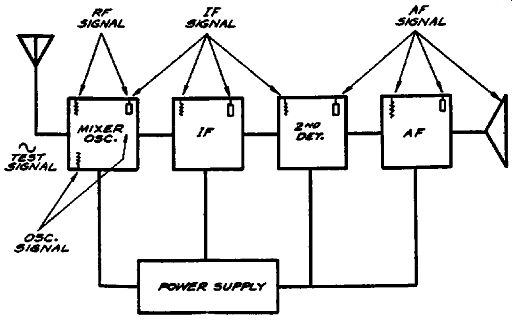
FIG. 1-1. A simple superheterodyne receiver in block form showing the principal
signal test points. The input and output of each stage are identified by the
grid and plate symbols.
Now, if you compare these two block diagrams, you will note that there is no difference in signal-testing routine. In other words, the increased number of tubes and the change in circuits does not alter the general test locations. All that is changed is the number of signal test points at radio frequencies, intermediate frequencies, audio frequencies, etc. Even this statement is subject to qualifications, for while we show the increased number of signal test points, it does not necessarily mean that the signal is checked at each of these points. If you recall, the statement was made that complete sections of a receiver can be checked just as readily as individual components, so that it is possible to check the complete i-f system in Fig. 1-2 by working between the output of the mixer and the input of the demodulator (second detector), a test which is identical to that made in Fig. 1-1, although the number of tubes and individual test points in Fig. 1-2 is greater than in Fig. 1-1.
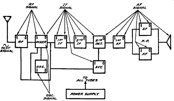
FIG. 1-2. Block diagram of a superheterodyne receiver showing the major signal
test points. The r-f, i-f, and a-f sections of the receiver are indicated.
The routine of establishing facts concerning the signal is exactly the same in both cases, although the man who works upon the receiver must recognize certain inherent difference between the two receivers. He must recognize, after glancing at the block diagram which is used in place of the regular schematic, that Fig. 1-2 employs an r-f stage, an avc system, an added i-f stage and a push-pull stage. The reason for stressing this recognition of variations is in order to mention that the operator must know what tests are to be made and what the condition of the signal should be at the various points of test.
In this connection, the man must know that the r-f stage is supposed to provide a certain amount of amplification, that the intermediate-frequency signal actuates the avc tube, that proper operation of the push-pull audio stage means substantially equal signal voltages at the two input grids and likewise at the two output plates of the push-pull stage. He must also recognize the manner in which the signal voltage varies between the output circuit of say the audio tube and the speaker circuit.
It is, of course, our intention to deal with all of these items later on in this book, but reference is made to them at this time in order to avoid any erroneous impressions. However, as far as the signal-tracing process is concerned, Figs. 1-1 and 1-2 are treated in like manner.
Let us take a still more complicated receiver, one with a greater number of tubes. This is shown in block form in Fig. 1-3. A separate avc amplifier is employed in this system and a push pull a-f stage has been added. As far as signal tracing is concerned, these additions merely mean just so many more points of test. The avc amplifier adds two additional places where, when necessary, the intermediate-frequency signal may be checked.
The added driver stage increases the a-f signal test points by four positions.
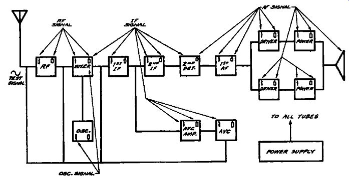
Fig. 1-3. Block diagram of a superheterodyne receiver showing the major signal
test points. A separate channel is used for avc amplification.
The special circuit variations represented by the coupling units do not enter into this discussion. This was mentioned before. It does not matter whether the intermediate-frequency transformers are dual winding or triple winding, or whether the audio stages are transformer-coupled or resistance-coupled, the various portions of the coupling units or the devices employed in conjunction with the various tubes become items of interest only after the test shows a defect in the form of a change from a normal signal.
Another example of circuit structure is shown in Fig. 1-4.
This is a double superheterodyne embracing two oscillators, two mixers, an automatic volume control system and automatic frequency control. Despite the major differences between Fig. 1-4 and Figs. 1-1, 1-2 and 1-3, the same general routine of signal tracing applies. The various frequencies designated on the block diagram are purely illustrative and are used to show how, in …
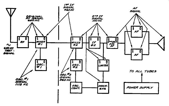
Fig. 1-4. Block diagram of a double superheterodyne receiver showing the
major signal test points. The frequency of the second oscillator is automatically
controlled by the afc system.
… the case of the two intermediate-frequency amplifier sections, the signal is checked at two different intermediate frequencies. Naturally the two oscillators would also be checked at two frequencies, each being in accordance with the frequency of the input signal to the associated mixer and the required i-f peak.
The fact that superheterodyne receivers are used in these examples does not bear any special significance. We show them here because this type of receiver is most popular; however, tuned-radio frequency receivers could be used equally well and if a number of types were shown, the similarity in signal tracing would still prevail.
The moment is opportune to speak of multi-band receivers. As you will note, no special mention has been made concerning the number of wavebands, frequency range, or the classification of utility of the receiver. As was mentioned earlier in this text, no particular discussion is required because the variations mentioned do not in any way change the manner in which signal tracing is applied. As a matter of fact, the number of test points is not even increased when the receiver is of the multi-wave type as against the usual single-frequency type, or when an aircraft or police receiver is compared with a home broadcast receiver of equal number of tubes.
By and large, the determining factor with respect to the number of general signal-tracing points is the number of tubes and not the exact circuit. Of course if the occasion arises when it is necessary to backtrack in the coupling unit because proper signal transfer between two tubes is not obtained, then the exact number of test points depends in some measure upon the type of coupling unit. However, due to the similarity between coupling units, such as among the r-f systems, or among the i-f or a-f systems, the possible variations which will increase the number of signal test points are comparatively few. These will be dealt with later. In fact, a portion of the discussion in a later section is devoted to the manner in which various types of coupling units operate in different circuits and what is to be expected in the nature of performance from these coupling units and the relation of this performance to the signal voltage.
No matter what receiver you might select, you will find that it is possible to illustrate that receiver in block form similar to that shown in Figs. 1-1 to 1-4, and to establish the various signal tracing test points in exactly the manner illustrated. As a matter of fact, the man who has had experience reading schematics does not find it necessary to draw such block diagrams. He can instantly determine the various test points by examining the schematic.
In connection with these signal test points, it is of interest to mention that while we refer to signal-tracing test points as being the input and output circuits of the various vacuum tubes in the system, and while we show these test points as being the control grid and plate of the respective tubes, there is no set rule that these tube elements must be used. It is possible to use as an equivalent test point, the junction between the control grid and the component connected to the grid or the junction between the plate and the component connected to the plate. Supplementary to the above, you must also realize that the occasion may arise when the signal should be checked at tube elements other than the aforementioned control grid and plate and also in places other than the actual coupling unit connected between two tubes. This will be discussed in a later section.
In each of the diagrams shown thus far, the oscillator appeared as one of the places where the signal was checked. We know, of course, that the function of this tube in a superheterodyne receiver is to generate the heterodyning signal. Therefore, when we speak of tracing a signal in the oscillator tube, we are referring to the signal being generated by that tube and not to the test signal fed into the receiver. You no doubt realize that the heterodyne signal generated by the oscillator tube has much to do with the manner in which the test signal will pass through the receiver or the manner in which the receiver will function. As in the case of the conventional test signal, the man who works upon the receiver must be familiar with the usual operation of such oscillators and know what information is desired and how to interpret it. This, like the other facts associated with signal tracing, will be discussed in greater detail later in this volume.
As in the case of the general receiver circuit, variations in oscillator-circuit design and tubes used do not present any limitations. As a general rule, the oscillator tube is one of the items which has rarely been checked in the past. Of course, efforts were made to check this tube by interpreting conditions in other related systems, but direct observations of such items as frequency, stability, or amplitude were seldom made. This is strange in view of the tremendously important role played by this tube and particularly when you consider that it may be, and frequently is, defective.
Control Voltage Testing
If you recall, we made mention of the fact that checking the control voltages was a vital function in the process of locating a defect by tracing the signal. Defining a control voltage so as to distinguish it from other d-c voltages found in receivers, we de scribe it as being that d-c voltage which is developed as the result of a signal and is employed to control the amplification provided in a tube or in a section of a radio receiver. Accordingly, we may encounter control voltages and control circuits in every portion of the receiver, as, for example, the radio-frequency amplifier, the intermediate-frequency amplifier and the audio frequency amplifier.
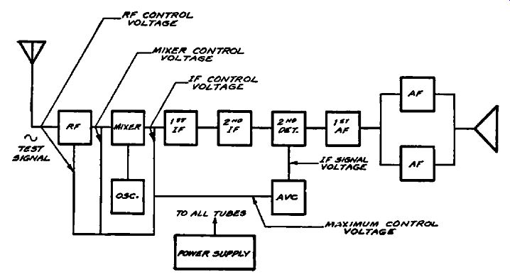
Fig. 1-5. Block diagram of a superheterodyne receiver showing the location
of the control voltages.
Figs. 1-2, 1-3 and 1-4 contain various control circuits as they appear in radio-frequency and intermediate-frequency systems.
In order to simplify the explanation, we shall repeat Figs. 1-2, 1-3 and 1-4 as Figs. 1-5, 1-6 and 1-7 respectively, but in the second group show the test points for the various control voltages in order to illustrate that all control systems can be checked with equal ease. The process of testing control voltages is identical to that used to check signal voltages. Of course, there is a difference between the two voltages, the control voltage being of d-c character and the signal voltage being of a-c character, but the process of checking these voltages and interpreting them in terms of the action upon the signal consists of nothing more than establishing four essential facts. These are: (1) the function of the control voltage, (2) the source of the signal applied to the input of the control tube, (3) the control tube itself, and (4) the manner in which the control voltage is distributed to the various control points. This assignment should be within the province of every man who has occasion to work on radio receivers.
As in the previously mentioned cases of signal tracing, variations in control circuits mean nothing more than variations in the source of the signal voltage fed into the tube that develops the control voltage. It might be an i-f signal secured from any number of places in an i-f system and by various coupling means, or it might be an a-f signal secured from some place in the de modulator or audio system. Hence, a variation in the control system means a variation in the kind of signal being checked at the input of the tube which generates the control voltage and the point at which this signal is checked. Also, it may mean a variation in the number of points at which the control voltage developed in a tube is fed to the other tubes. Expressed differently, this would be a variation in the number of places where the control voltage is measured, depending entirely upon the design of the individual receiver.
For example, in Fig. 1-5, a tube marked "AVC" is used to develop the automatic-volume-control voltage. The i-f signal is secured from the second intermediate-frequency amplifier and the control voltage is fed to the r-f, mixer, and first i-f tubes. The exact type of tube being used to develop the avc voltage is of no consequence. The avc voltage is developed at the output circuit of this avc tube and this voltage is then distributed to the various tubes under control. In a circuit such as this, there are four basic control-voltage test points: the source and the three control grids which receive the control voltage. We of course assume, as has been stated before, that the device used to measure these control voltages is of such design as not to interfere in any way with the normal operation of the circuits, that is, it does not load the circuits. In the event that the control voltage does not appear at the end of the various distribution points, then additional test points may be found in the distribution channels so as to identify the exact point where interruption of the circuit occurs.
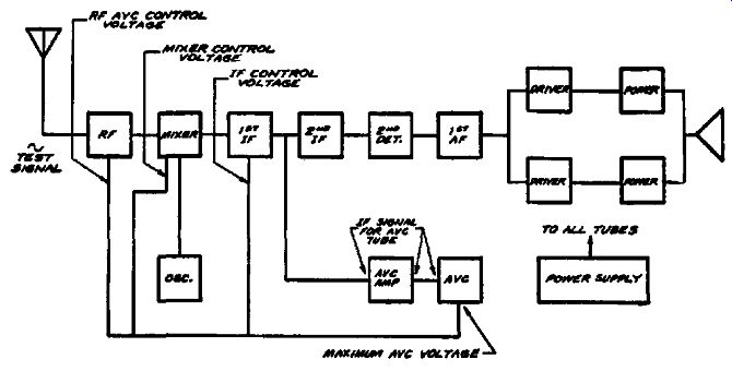
FIG. 1-6. Block diagram of a superheterodyne receiver with a separate channel
for ave. The distribution of the control voltages is indicated.
If you now examine Fig. 1-6, you will find that while the number of tubes used in the receiver is greater than in Fig. 1-5, and while a separate amplifier has been provided to feed the avc tube and, further, while the i-f signal for the avc amplifier tube is secured from a different point in the intermediate-frequency amplifier, the number of control voltage test points in Fig. 1-6 is the same as in Fig. 1-5. In other words, the number of test points does not necessarily change with changes in receiver design. It is possible, as in the case of Fig. 1-6, that the input circuit to the avc tube changes, but the general selection of the test points is governed entirely by where the control voltage is fed.
What is said is true without any modifications in the case of second-detector or demodulator tubes which also include the function of generating the avc voltage. This tube may contain a separate diode which rectifies the i-f signal voltage and develops the control voltage, or the avc voltage may be obtained from the second-detector load circuit. Whatever system is used, it should be understood that the avc voltage exists at the source, and that the test points, irrespective of the original source of the avc voltage, are those places where the avc voltage is fed to control the tube.
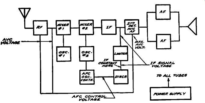
Fig. 1-7. Block diagram of a double superheterodyne showing the distribution
of the control voltages. Both afc and avc voltages are shown.
An interesting control system is illustrated in Fig. 1-7. In this double superheterodyne we find both automatic volume control and automatic frequency control as well as a "limiter" tube.
Suppose that we start with the automatic-volume-control system.
Note, if you please, that the avc tube is also the demodulator and the first a-f tube. This is of no consequence, because in the actual schematic one of the diodes within this multi-purpose tube is the avc diode, and consequently the load circuit of this diode represents the point where the maximum avc voltage is developed. The i-f signal required to actuate this diode is obtained from the stage identified as IF. The tubes which are controlled by this avc voltage are the r-f and mixer No. 1, so that the control grids of these two tubes, being the final destination of the avc voltage, become the control-voltage test points.
You can readily see that the selection of these avc test points is no more difficult in the case of this complicated receiver than in the two simpler receivers already described.
Now for the automatic-frequency-control system. We note that the i-f signal is fed to a tube identified as a "limiter," the function of which is to maintain the i-f signal voltage fed into the discriminator virtually constant irrespective of the signal voltage at the input of the limiter tube. This is accomplished by utilizing a self-biasing action within this tube. At low signal input levels the maximum amplification is secured within this tube and a definite output is fed into the discriminator. however, as the signal input to the limiter rises above a certain value, this tube starts drawing grid current and a voltage is developed across the grid leak in the grid circuit of the tube. The d-c voltage developed across this grid leak as a result of the grid current tends to reduce the amplification provided by this tube and thus tends to keep the output constant.
According to the above, the limiter tube is therefore associated with two types of tests. One of these is to check the level of the i-f signal output for various input signal values and the second is to note the d-c voltage, which we can, for want of a better name, call an automatic control or limiting voltage developed across the grid leak. Hence, the control grid of the limiter tube is a point where we can check this d-c limiter-control voltage.
This, as you can readily see, is in exact accordance with the manner in which the tube is supposed to operate. In other words, we are checking the tube in accordance with its function.
Going now to the discriminator, the known function of this device is to develop a d-c (afc) voltage which varies within certain positive and negative limits through zero, in accordance with the frequency of the i-f signal. If, assuming correct tuning in the discriminator circuit, the i-f signal is of the correct frequency, then the output d-c voltage from the discriminator is zero. If the i-f signal fed into the discriminator is off resonance, the discriminator output d-c voltage will be negative or positive, depending upon the discrepancy between the i-f signal frequency and the resonant frequency of the discriminator output circuit.
Hence, the basic test point for the afc voltage is as designated, the output of the discriminator.
This afc voltage is fed to the afc oscillator control tube, which controls the frequency of the oscillator, in this case oscillator No. 2, so that the test point in the oscillator control tube circuit is that place to which the control voltage is applied, namely the control grid.
Now, in accordance with the function of the discriminator, the output circuit of this tube is the place where the d-c control voltage is checked to establish correct tuning or incorrect tuning, and also, by establishing the polarity of the d-c control voltage, to determine the direction of the off-resonant state. There is nothing tricky or involved in making this voltage test. The test conforms entirely with the function and purpose of the discriminator tube.
We can go beyond this test of discriminator output and establish the manner in which the afc oscillator control tube varies the frequency of the oscillator. The idea behind the entire system is the variation of the oscillator frequency to produce the correct intermediate frequency in the event that the initial oscillator tuning of the receiver is incorrect. This is done by noting the variation in frequency of the i-f signal developed in the output of the mixer tube, in this case mixer No. 2, with and without afc for the original state of receiver tuning. This test is a function of signal tracing.
You can readily see, from the three examples of control voltage measurement, that in every case the design and function of the control circuit does not complicate the determination of the presence of the control voltage at the various controlled points and the manner in which the control circuits function. In every instance, the tests are made in accordance with the manner in which the various circuits operate. Whatever the design of the system, the control voltage is checked where it is developed and where it is distributed; when desired, its effect can also be checked. For example, signal tracing provides for a simultaneous test of the signal level and the control-voltage level, and thus establishes whether the control voltage applied to a certain tube is actually performing the required controlling action.
This reference to the relation between signal voltage and control voltage levels is extremely brief. Since this subject deserves a more elaborate discussion it will be more completely described in a later section.
Audio Circuits
Up to the present time we have devoted very little space to audio circuits. This has been deliberate as we do not deem it necessary to enter upon a lengthy discussion of that subject at this time. Particularly so, when all that need be said now is that the process of signal tracing in an audio system follows along the lines thus far shown. In each and every case the signal test points are selected in accordance with the design of the circuit and the function of the components.
Each and every circuit used in an audio system is checked or tested in accordance with the role it plays with respect to the signal as a whole or as regards some of the frequencies or a range of frequencies present in the final audio signal. This latter reference takes care of automatic bass expanders and automatic volume expanders, each of which receive its full allotment of space in a subsequent section.
Tubes and coupling elements utilized to secure audio degeneration, phase inversion and the like, are treated entirely from the angle of what happens to the signal. If certain signals of pre determined levels with respect to the level at some other point are supposed to exist at certain places, then these signal voltages are measured quantitatively or qualitatively, whichever may be deemed necessary, in those circuits where they are supposed to appear.
If the design of the audio system is such that specific control voltages developed by weak or strong signals, whichever they may be, are intended to block the amplifier, as, for example, for noise suppression, these circuits are checked according to their function, with the signal and control voltages as the final barometers.
The circuit design utilized in the audio system does not impose any limitations and, as stated earlier in this text, we are not passing lightly over the arduous hours spent in the design of a high-caliber audio system which performs any number of special functions. Audio systems, like radio-frequency and intermediate frequency amplifiers, are intended to operate upon a signal, and that is how they are checked, inclusive of whatever control actions are supposed to exist or whatever division of frequencies is supposed to take place in the various channels. Every condition which might develop in an audio amplifier and which will in any way impair the signal comes within the capabilities of signal tracing with utmost ease.
We pass on from this introductory section with the hope that we have shown how the signal tracing process of trouble detection or localization is so basic as to be independent of the many factors which contribute to form a communication system and which are subject to variation in accordance with the demands of the industry and the preferences of the men who design equipment.