AMAZON multi-meters discounts AMAZON oscilloscope discounts
Amplification is essential in every radio communication system. Both in transmission and reception vacuum tubes are used as magnifiers or amplifiers of the signal. In the receiver, which is of primary interest to us, amplification is necessary in order to enable the proper reception of weak signals or to provide an output signal which is of the desired strength. As a matter of fact the development of the property of amplification in a vacuum tube is directly responsible for the very existence of modern communication systems of all types. Remove the amplification provided by the transmitting and receiving systems and our present-day communication facilities of the world are virtually at a standstill.
Our interest in amplification is not one of design; that is to say, we are concerned with the practical rather than the theoretical. We know that many millions of radio receivers are in use and that these receivers incorporate amplifying systems. Our attention is focused upon the comprehension of the manner in which these systems function and their correct maintenance. In this connection, the basis is the signal which is being amplified. What happens to the signal during amplification? How is it distributed throughout an amplifier? How can we locate a defect in such an amplifying system most effectively and rapidly?
... These are the questions we must answer.
Needless to say we cannot omit all reference to the basis of amplification within the vacuum tube. We must of necessity discuss some of the theoretical details, but when we do so, every at tempt shall be made to translate the findings into practical terms.
Types of Amplifiers
Speaking in generalities, there are two basic types of vacuum tube amplifiers in daily use in radio receivers. These are ( 1) voltage and (2) power. In the former, the design of the amplifier is such as to provide the maximum output signal voltage. Such amplifiers are usually used in cascade, that is, one stage feeding the next, and the highly amplified output voltage of the series is then either rectified or fed to a power amplifier. The power amplifier functions in a manner similar to the voltage amplifier, but with the difference that the amplifier provides maximum power output instead of maximum voltage output.
As far as signal tracing is concerned, both voltage and power amplifiers are handled in like manner. It is simply a matter of interpreting the output under the actual operating conditions and analysis of these operating conditions with respect to the components to make certain that they are conducive to whichever· type of amplification is desired. If we recognize that the signal voltage output in a power amplifier is of necessity less than that of an equivalent voltage amplifier, signal tracing calls for the establishment of correct signal voltage conditions, both as to level and character of the signal. This operation is aided very greatly by the fact that power amplification is usually limited to the audio system and then invariably to the final stages.
References to voltage amplifiers in conjunction with audio systems should not be construed as meaning that voltage amplifiers are limited to audio systems. We intend anything but that. Voltage amplifiers are used as radio-frequency amplifiers, intermediate-frequency amplifiers and in audio systems to feed the power stage. As a matter of fact all r-f and i-f amplifiers in radio receivers are voltage amplifiers. This is quite natural in that we want the highest possible signal voltage in such systems because it provides the required sensitivity and further because the output of the voltage amplifiers is fed to the detector for rectification.
In appearance there is very little difference between voltage and power-amplifier tubes. In general the power-amplifier tubes are slightly larger, but in all other respects they look alike. In tern11lly the tubes are also similar in the number of elements or electrodes, although it is true that the internal structure of the tubes is different. By structure we mean the spacing between the various electrodes, the size of these electrodes, etc. As to the amplifying capabilities, the power amplifiers do not amplify the signal voltage as much as the voltage amplifiers. The extent of this distinction will become more evident as we progress through this discussion.
As far as associated circuits are concerned, the general structure of the input circuits feeding voltage and power amplifiers is similar. This is quite reasonable in that both voltage and power amplifiers are voltage-operated, hence similar types of input circuits are used to supply the maximum signal voltage to the input of the tube. The output circuits of voltage and power amplifiers, while often alike in appearance, constitute the place in the system where differences will be found. Thus, for example, output circuits of power amplifiers almost invariably are low impedance circuits, which is not true in the usual run of voltage amplifiers. However, it is not always possible to identify one or the other type of amplifier by a quick examination of the schematic of the output circuit. More often, the intended function and tube type number identify its operation as a voltage amplifier or as a power amplifier stage.
So much for the general discussion of the types of amplifiers.
We want you to realize this discussion is by no means complete, but in view of what follows later in this volume, what has been said can suffice for the present.
Amplifying Property of the Vacuum Tube
Undoubtedly every man who reads these lines is familiar with the property of amplification possessed by certain types of amplifier tubes. Nevertheless we feel that best interests will be served if a general review of such action is included at this time. It will serve well in explaining not only the action of amplifier tubes in conjunction with signal tracing, but it will also facilitate an understanding of the manner in which detectors perform their functions.
By no means do we intend this as a full and complete explanation of amplifier operation. Frankly, we do not feel that such an explanation must be complete in order to fill our needs. In fact it would be impossible to do this subject full justice in a volume such as this; it could very easily occupy several volumes of its own. However, it is still possible to convey amplifier information from the viewpoint of signal tracing, which in general is not employed in the conventional text books. In accordance with this belief, we offer the following.
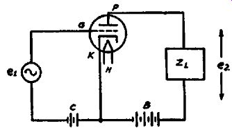
Fig. 2-1. A triode used in a simple amplifier circuit. ZL represents the
load across which the output signal is developed.
The triode tube is the simplest amplifier; simplest in that it possesses the capability of amplification and yet employs the fewest number of elements. Such a triode tube utilized in an amplifier circuit is shown in Fig. 2-1. The various tube element symbols are conventional and hence require no explanation. The same applies to the batteries. The letters "ei" and "e1" represent the input signal voltage fed into the grid circuit and the output signal voltage respectively. The letters "ZL" represent the load impedance in the output circuit of the amplifier, or expressed in other words, the device across which the amplified signal voltage e2 appears.
The structure of the tube is such that the control grid is located between the cathode and the plate and the operation of the tube is as follows: The heater H causes the cathode K to acquire an electron-emitting temperature. These electrons accumulate in the space between the cathode and the control grid G. If a positive voltage is applied to the plate, it exerts an attracting force upon the electrons emitted from the cathode and current flows between the plate and cathode and through whatever devices, such as ZL in Fig. 2-1, are connected between the cathode and plate and are external to the tube. The higher the positive voltage applied to the plate, the greater the number of electrons attracted to the plate, and hence the greater the value of plate current. Naturally, the reverse is true; that is, the lower the plate voltage the fewer the electrons that are attracted to the plate. Incidentally it might be well at this time to mention that some of the electrons will reach the plate even when no positive voltage is applied to the plate, that is, when the plate voltage is zero.
This is due to the fact that the initial velocity of some of the electrons emitted from the cathode is sufficiently great to cause them to reach the plate.
Now, since the control grid is located between the cathode and the plate it is in a position where it exerts an effect upon the emitted electrons and therefore can control the number which will reach the plate. If a negative voltage C in the form of a grid bias is applied to the grid, it will repel some of the electrons emitted from the cathode and prevent their approach to the plate, thereby reducing the plate current. Since the grid is located closer to the source of the electrons than the plate, a small negative voltage applied to the grid can off set a much higher positive voltage applied to the plate. The greater the negative voltage or bias applied to the control grid, the greater the repelling action upon the electrons and the smaller the plate current. Thus a definite relation exists between the grid voltage and the plate current and herein lies the ability of the vacuum tube to amplify.
You will note that we speak of negative grid bias voltages.
This is done because practically all amplifiers which employ a grid bias, employ a negative bias. This bias is vital in such systems because it prevents the attraction of electrons to the control grid and hence the flow of current in the external circuit between the control grid and the cathode or filament. In this connection it might be well to point out that there is a distinction between any action on the part of the grid to change the electron flow towards the plate and the attraction of electrons to the grid.
Attraction of electrons to the grid is usually undesirable because it causes the flow of grid current with consequent distortion and reduction in amplification.
When the control grid of an amplifier tube is maintained at a negative potential so that it does not attract any electrons to it self, the grid circuit of the tube, that is the input circuit of the tube, becomes the equivalent of a very high impedance. As a result it docs not load the device which feeds the input signal to the tube and distortionless amplification is possible, provided that the other proper operating requirements are also fulfilled.
In some instances that we will show later in this volume, certain amplifier tubes operate with zero bias and substantial amounts of grid-current flow. Proper compensation is employed in such circuits to offset the effects of grid current. We make this reference in order to avoid the criticism which would be due if it were omitted and the previous statements were accepted as covering all types of amplifiers.
Plate Current
To comprehend the operation of the amplifier tube properly, it is essential that you understand the part played by the plate current. We made the statement that a positive voltage applied to the plate of the tube, such as that available from the battery Bin Fig. 2-1 or from some other plate-voltage source, will attract some of the emitted electrons. The result is the flow of plate current in the plate circuit. In connection with this reference to the plate circuit, we find a number of very significant points. In the first place, the plate circuit embraces a number of tube elements and associated components. For example in Fig. 2-1, the plate circuit includes the plate of the tube, the cathode, the plate voltage supply B and the load impedance ZL. Whatever plate current flows in this circuit, flows through all of the parts mentioned. The load ZL, located in the output circuit and across which the amplified signal appears, can be a resistor, a trans former or a choke without in any way altering the path of the plate current.
The magnitude of the steady value of the plate current is of course controlled by a number of factors, among which are the operating voltages, the design of the tube, which means its characteristics, and the d-c resistance of the load impedance ZL, By steady value of plate current we mean that value which is the result of the operating voltages and the other factors mentioned in the previous sentence and that which exists without any signal input to the tube. This leads us to a further explanation of the plate current.
When no signal is fed into the amplifier tube, the plate current has a steady value, but when a signal is fed into the tube a change takes place in the plate current. It might seem premature to mention this change now without showing the actual action, but we cannot omit the reference because we are speaking about plate current. The basis for this variation in plate current will be shown later in this section, but Jet it suffice for the present to say that a signal voltage applied to the grid causes a variation in the plate current from this steady value, thus when a tube is operating as an amplifier, the plate current is a combination of a steady value upon which has been superimposed an alternating current which corresponds in shape or wave-form to the signal voltage applied to the grid. In other words, the plate current is a pulsating current.
In connection with the plate current, one point is of tremendous importance. It is paramount because of the bearing it has upon the application of signal tracing as a means of locating defects in amplifiers. It is the condition that wherever a path exists through which this pulsating plate current flows and this path has some value of resistance, reactance or impedance, an a-c voltage will be developed. This a-c voltage will be a signal voltage . . . This is our basis of operation. It is possible that means are included in the amplifier system to minimize the magnitude of this a-c signal voltage, but basically what we said is true and if re membered will be of great aid in signal tracing. Thus in the simple circuit of Fig. 2-1, where no special precautions are taken, the pulsating plate current flows through the tube, the cathode circuit, the plate-voltage supply, B, and the load impedance, ZL, Any portion of this complete circuit which contains resistance, reactance or impedance will cause a signal-voltage drop.
Thus if we assume ZL to be a resistor and the plate-voltage supply B is assumed to contain some value of resistance, then a signal voltage drop will take place across the terminals of ZL and across the terminals of the supply B. This description is brief, but appropriate at this time because of the significant nature of the subject.
We said earlier in this section that the presence of the control grid between the cathode and the plate and its ability to control the plate current gave rise to the ability of the tube to amplify.
Just what is meant by this statement is illustrated in Fig. 2-2. In this graph you can see how a small change in grid voltage has the same effect upon the plate current as a much greater change in plate voltage. Each of the curves is identified with respect to plate voltage designated at the top of the curves. The vertical axis indicates the plate current and the horizontal axis shows the grid voltage. FIG. 2-2. The variation in plate current with grid voltage for three different values of plate voltage. As explained in the text, the grid is more effective than the plate in controlling the plate current.
Thus the three curves represent the plate current-grid voltage relationship for plate voltages of 120, 150, and 180 volts.
Let us now show how the grid voltage is more effective than the plate voltage in controlling the plate current. Starting at point a which shows that the plate current has a value of 3.4 ma for a plate voltage of 120 volts and a grid bias of -8 volts, let us assume that the plate voltage is raised to 150 volts without any change in the grid bias. The new plate current, as represented by point b will then be 6 ma. To determine the effectiveness of the control grid, we must now find the amount by which the grid bias must be changed to off set exactly the increase in plate Current brought about by the increase in plate voltage from 120 to 150 volts. If you will refer to the curves, it will be clear that the grid bias must be increased to 10.8 volts, as shown by point c, in order to bring the plate current back to its original value of 3.4 ma. Thus, an increase in grid voltage from -8 volts to -10.8 volts is just as effective in controlling the plate current as is an increase in plate voltage from 120 volts to 150 volts.
The amplification factor of a tube deals with the :relative effectiveness of the grid and plate voltages in controlling the plate Current, and as we should expect, the amplification factor is equal to the ratio between the change in plate voltage and the corresponding change in grid voltage which is required to produce the same change in plate current. In the example above, a change in plate voltage of 30 volts produced a change in plate current which was offset by a change in grid voltage of 2.8 volts. The ratio between 30 and 2.8, 30/2.8 = 10.7 thus indicates that the grid is 10.7 times as effective as the plate in controlling the plate current and therefore the amplification factor of the tube is said to be 10.7.
This relation between the grid-voltage change and its effect upon the plate current is not characteristic of the triode tube alone. All vacuum tubes-triodes, tetrodes, pentodes-all tubes capable of amplification and used in communication systems act as amplifiers because of this action between the grid and plate circuits. In fact all such tubes capable of amplification bear an amplification-constant rating denoting this amplifying ability.
The exact value of 10.7 used in the example is purely illustrative. In some tubes this factor is much higher, sometimes amounting to 1500 or more and in other types it may he very low, such as 3 or 4. Tubes intended as voltage amplifiers generally have higher "IL" ratings than tubes intended for use as power amplifiers.
The importance of the amplification factor IL is that it expresses the maximum amount of amplification obtainable with the tube in question. That is to say, a tube rated at a IL of 7, is capable of a maximum gain of seven times the signal fed into the tube, provided that the requirements for distortionless amplification are fulfilled. A tube rated at a IL of 100 is capable of amplifying a signal a maximum of 100 times, etc.
However, there is a tremendous difference between the value of amplification indicated by the amplification factor and the value actually realized in the complete stage, including the tube and its associated external components. The maximum theoretical amplification is never realized in practice but it is nevertheless important to know what this maximum value of amplification is, because it enables the determination of the actual amplification being obtained. When we speak of the actual value of amplification we mean the relative gain or increase in signal level between the input to the tube and the output secured across the load impedance. What we get out of the tube is far more important in practice than the possible amplification indicated by the value of the amplification factor.
Plate Resistance
Supplementary to the amplification factor, there is another tube constant which has a definite bearing upon our subject. This is plate resistance. Plate resistance is the opposition offered by the tube structure to the flow of plate current. This phenomenon takes place within the tube, within the space between the electron emitter and the plate and is essentially a function of such items as the spacing between the electrodes, the area and number of the electrodes, etc., but it is also influenced by the operating voltages. However, for any one set of operating voltages, the tube structure is the determining factor. Plate resistance is measured in terms of ohms.
A general relation exists between plate resistance and amplification constant. Although it is not invariably true, it is generally the case that the higher the amplification constant, the higher the plate resistance, which means that as a rule, voltage amplifiers have higher values of plate resistance than power amplifiers. This applies to all types of tubes: triodes, tetrodes, pentodes, etc. Associated with the subject of plate resistance is plate current. The higher the plate-resistance of a tube for a given set of operating voltages, the lower is the plate current.
This is only natural in view of the usual relation between resistance and current when the voltage is fixed.
The plate resistance of a tube, indicated by the symbol r_p, is the a-c plate resistance and should not be confused with the d-c plate resistance. As the name implies, the d-c plate resistance is equal to the d-c plate voltage divided by the d-c plate current and it indicates the resistance of the tube to the passage of direct current. On the other hand, the a-c plate resistance, with which we are primarily concerned in this book, is a measure of the op position which the tube offers to the passage of the signal. In all computations which involve the signal, it is the a-c plate resistance that is important since it, is this value which determines how much of the maximum possible amplification will be obtained. The plate resistance value appearing in tube tables is ordinarily the a-c plate resistance unless otherwise stated.
You will see later that a definite tie-up exists between the load impedance ZL in Fig. 2-1, the plate resistance and the amplification constant. For any one particular tube, the higher the ratio of the load resistance to the plate resistance, the higher is the amount of voltage amplification realized with the stage.
Mutual Conductance
Mutual conductance is the last of the three major tube constants. Identified as "gm" and expressed in terms of micromhos (the mho is the reciprocal of the ohm), it is a measure of the amount of amplification obtainable under actual operating conditions. More specifically, it expresses the microampere change in plate current for a unit change in grid voltage; consequently it embraces the structural features of the tube, the amplification constant, the plate resistance and the operating voltages.
The greater the mutual conductance of a tube, the greater will be the change in plate current for a given change in grid voltage.
Thus a tube having a mutual conductance of 800 micromhos will produce a change in plate current of 800 microamperes when the grid voltage is changed by 1 volt; a tube having a mutual conductance of 5000 micromhos will produce a change in plate Current of 5000 microamperes (5 ma) when the grid voltage is changed by 1 volt. It should be kept in mind that the change in plate current expressed by the value of gm assumes that the load resistance is zero. For any value of load resistance, other than zero, the change in plate current will be proportionately smaller as the load resistance is increased.
Of importance is the fact that the value of gm does not indicate the maximum amplification which can be obtained from a given tube. Thus one tube having a lower gm than another tube may provide a considerably greater value of signal or voltage amplification. We will explain the reason for this condition in detail later in this section.
Process of Amplification
Having discussed some of the highlights of amplifier tubes, we are ready to investigate the process of amplification. How does the amplified signal appear in the plate circuit of the tube? The answer to this question will explain the presence of the a-c or signal component of the plate current.
We said that a change in grid voltage will cause a change in plate current. Let us analyze this statement and use the simple triode circuit shown in Fig. 2-3 and illustrate the action by means of a graph, which is shown in Fig. 2-4. You will note that the ...
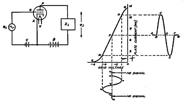
FIGs. 2-3, 2-4. A simple triode M1 amplifier circuit is shown in Fig. 2-3,
above. When a signal is applied to the grid, the plate-current variations
follow the grid voltage variations as shown at the right.
...vertical axis in the latter is identified as plate current and the horizontal axis is identified as grid voltage. To the right of the plate current axis is the plus or positive region of grid voltage and to the left of the plate current axis is the minus or negative grid-voltage region. You will also note a sloping line QNPMR. This is the grid voltage-plate current characteristic, and it shows the variation of plate current with grid voltage when the plate supply voltage is fixed Further examination of the grid voltage-plate current characteristic shows that this sloping line has a fairly straight portion and that the two limits are curved. The portion between M and N is the straight or linear portion and is the useful portion of the characteristic. It is over this region that the plate-current variation is uniform or linear with respect to changes in grid voltage.
However between N and Q, the plate-current variation no longer is uniform and the same is true between M and R; hence operation over these portions will be non-linear and result in distortion.
Now in order to provide operation over the linear portion of the characteristic it is necessary to select a certain point along this characteristic which will permit uniform variation in plate current over a range of input signal voltages. This point is determined by the magnitude of signal voltage which is to be applied and also the length of the characteristic as determined by the plate voltage. For our illustration, P is the operating point and it is established by the use of a negative grid-bias voltage of approximately 2.8 volts. With this amount of grid bias employed, we can apply a signal voltage and cause the plate current to increase and decrease equally in both directions around the operating point P. If this point P is projected to the plate-current axis, it identifies the no-signal steady plate current as being approximately 7.2 milliamperes. This is the value of plate current which is assumed to flow through the entire plate circuit of Fig. 2-3 without any signal input to the control grid.
Directly below the negative region along the grid-voltage axis is shown a single cycle of a-c voltage. This is the signal voltage and for convenience we assume that its frequency is so low that the variations in amplitude can be followed. What is the effect upon the plate current of this variation in grid voltage? Inasmuch as it is customary to consider the half cycle above the zero reference line of an a-c voltage to be positive, such a voltage applied to a grid which is biased negatively will have the effect of off setting the bias by an amount equal to the peak value of the a-c voltage. This is the equivalent of reducing the effective bias, and hence increases the plate current. Let us now assume that the line a-b represents no-signal input and that the line A-B adjacent to the plate current axis represents the steady no-signal value of plate current; then if a signal voltage corresponding to b-c is applied, the plate current will increase from the steady value as shown by line A-B to point C and the plate current variation B-C then will correspond to the grid voltage variation b-c.
When the signal voltage applied to the grid decreases from c to d, it is the equivalent of an increase in bias because the amount of signal voltage which offsets the bias decreases from its peak value to zero at d. The result is a decrease in plate current throughout the entire plate circuit and the corresponding change in plate current is shown by the plate-current variation C-D. Thus, during the half cycle of grid voltage change, a corresponding change has taken place in the plate current-starting from the no-signal value, reaching a peak, and then returning to the no signal value.
When the negative alternation of the signal voltage is applied, it is the equivalent of increasing the effective bias, so that the net result is a decrease in plate current, starting from the no signal value. The negative signal-voltage alternation d-e-f results in an equivalent change in plate current D-E-F, which of course takes place throughout the plate circuit of Fig. 2-3. You can readily see that under the ideal conditions which we assume to exist in this circuit, the plate-current variation caused by the change in grid voltage corresponds in waveform with the signal voltage applied to the grid.
We spoke about ideal conditions. What do we mean by ideal conditions? First, if you will examine Fig. 2-4, the magnitude of the positive half of the signal voltage wave is less than the grid bias applied, which means that the grid voltage swing does not exceed that permitted by the limits of the linear portion of the grid voltage-plate current characteristic. If the peak positive half of the input signal voltage wave exceeds the grid bias,-the grid will go positive, attract electrons, grid current will flow, and distortion will result. As we stated earlier in this text, certain types of amplifier operate with grid current. These will be discussed later.
Referring once more to Fig. 2-4, you should understand that once the correct operating point has been established with respect to the maximum grid swing, any value of signal voltage less than this maximum can be used, because it will result in operation upon the linear portion of the grid voltage-plate current characteristic.
In addition it might not be amiss to mention that the type of amplification being discussed is identified as Class A, wherein the output waveform is a faithful reproduction of the input signal voltage; the grid is never driven positive and the plate current as read upon a d-c meter remains the same with or without signal input. Voltage amplifiers are almost invariably operated as Class A amplifiers.
Plate-Current Variation and Signal Voltage
Having seen how the signal voltage applied to the grid causes a variation in plate current, you might ask about the development of the signal voltage in the plate circuit. This is quite simple in that the plate-current variation takes place throughout the entire plate circuit, consequently through the load impedance, no matter what its type. If the circuit structure of the amplifier resembles that of Fig 2-3, wherein the d-c component flows through the load impedance, two voltage drops develop across this load impedance. One of these is that due to the d-c component of the total plate current, which is the equivalent of the average value of the varying plate current. This is the voltage drop which could be computed by placing a d-c meter in the plate circuit, noting the current indication, and multiplying this value by the d-c resistance of the load impedance. The other voltage drop is the a-c voltage drop due to the varying current through the load; this signal voltage is the product of the a-c or signal component of the current and the impedance of the load at the frequency of the plate-current variation. Naturally in a class A voltage amplifier, the frequency of the a-c voltage in the plate circuit is the same as that of the signal voltage applied to the grid. This reference to frequency is not as strange as it might seem because under certain conditions we will discuss later the output circuit can contain frequencies which are multiples or harmonics of the frequency of the input signal voltage.
The process of amplification as outlined in Fig. 2-4 is applicable not only to the triode, but it is substantially the same in all types of voltage amplifiers and in many types of power-amplifier tubes.
In those types of power amplifiers where it differs, the variation takes place in the shape of the grid voltage-plate current characteristic, which of course is not a fundamental change. Thus when working with triodes, tetrodes, pentodes and the like, the process remains the same.
The sine-wave input and sine-wave output shown in Fig. 2-4 are purely illustrative. The output will not always to be a sine wave. It depends entirely upon the waveshape of the input signal voltage and the operating conditions. Assuming correct operating conditions, the output current variation will be an amplified reproduction of the input signal voltage so that if the input signal voltage is distorted, then the output will be distorted in the same way. If the input signal is a modulated r-f or i-f carrier, as shown in Fig. 2-5, then the amplified plate current variations will assume the shape of the modulated r-f or i-f carrier.
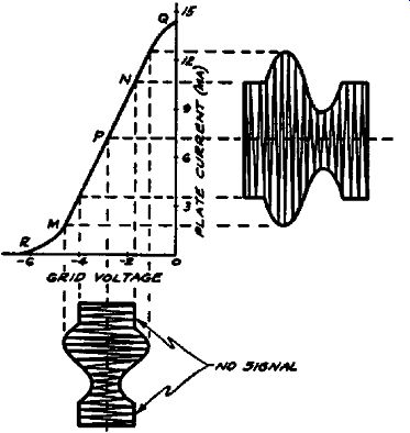
FIG. 2-5. When a modulated r-f signal is applied to an amplifier, the plate-current
variations have the same form as the input signal.
Phase Relations
We have already seen that when a signal voltage is applied to the grid, a corresponding amplified signal voltage is developed at the plate of the tube. If we take the case where a resistive load is used in the plate circuit of the tube, then we arrive at some important relations which are called the phase relations between the signal voltages at the grid, plate, and cathode.
To arrive at these phase relations, let us first consider what takes place when a more positive voltage is applied to the grid.
As a result of this more positive grid voltage, there is a corresponding increase in plate current. Similarly, when a more negative voltage is applied to the grid, the plate current decreases.
Thus the plate current is said to be in phase with the grid voltage since both go through their positive and negative peaks at the same time.
If we investigate the phase relations between the signal voltage at the plate and the input grid voltage, then we find that these two voltages are out of phase. Thus a positive increase in grid voltage causes an increase in plate current; this increased plate current causes the plate voltage to drop below the steady value which it has with no input signal. Similarly a more negative grid voltage than the steady value causes the plate current to decrease so that the voltage at the plate increases as a result of the de creased drop in the plate-load resistor. Thus the signal voltage at the grid is exactly opposite in phase to that at the plate since the one signal goes through its positive peak at the same instant that the other goes through its negative peak.
If a cathode resistor is used to supply the grid bias, the varying plate current will also develop a signal voltage across this resistor, unless the resistor is by-passed by a condenser. As a result of the direction of current flow, the signal voltage developed at the cathode is exactly in phase with the signal voltage at the grid.
Thus at the instant that the input signal makes the grid more positive, the increased plate current flowing through the cathode resistor also makes the cathode more positive with respect to its steady value. As we shall see later, this tends to reduce the net signal voltage effective between the grid and the cathode and thus reduces the amplification which is obtained. This effect will be discussed in connection with inverse feedback in a later section.
Tetrode and Pentode Amplifiers
So far we have mentioned the triode amplifier. All of us know that as radio progressed, the screen-grid, or tetrode, and pentode tubes were developed for use as amplifiers. These tubes differ from triodes in a number of respects, such as the number of elements and the operating characteristics, but as far as signal tracing is concerned, there is very little difference between the triode and these other tubes. Perhaps the added elements augment the number of test points under certain conditions, but in general we can consider them in the same way.
As far as the process of amplification is concerned, tetrodes and pentodes function in a manner similar to the triode. The change in grid voltage causes a change in plate current and the effect of the grid circuit upon the plate circuit is to produce an amplified signal in the plate circuit. The facts mentioned in connection with the ideal performance of the amplifier, that is, freedom from grid current, an input signal voltage which is limited by the grid bias, the plate current change being an enlarged image of the grid voltage change-all of these are true in tetrode and pentode tube circuits. However, the increased number of…
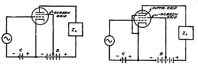
Figs. 2-6 (left), 2-7, (right). The use of tetrode and pentode type tubes
does not change the input and output circuits of the amplifier stage, which
are similar to those for a triode stage.
… elements changes the conventional amplifier circuit and examples of basic tetrode and pentode circuits are given in Figs. 2-6 and 2-7. If you compare them with Fig. 2-3, you will find that the variations are introduced by the added electrodes, and that the input and output circuits of the amplifiers are identical.
As to the difference between the triode and the screen-grid tube, our primary interest lies in the plate current. The actual functions performed by the added grids are not important here because in practice these elements are connected or operated in accordance with prescribed instructions and this information is available for comparison. With the plate current, however, we are concerned because of what was said in connection with the relation between the plate current and the appearance of signal voltage drops in the various portions of the system where the plate current flows. Accordingly, it is of special interest to mention that in the screen-grid tube, the total cathode current is made up of other currents in addition to the plate current. Thus in the tetrode, the cathode current, which is also the current drawn from the B-supply, is equal to the sum of the screen current and the plate current. Because of the structure of the screen and the plate and the relative voltages applied, the current in the plate circuit is several times that in the screen circuit; but you should remember that whatever variations are introduced in the space current by the signal applied to the grid, these are present in the screen current as well as in the plate current. As it hap pens, the circuit is generally arranged to nullify the effect of the a-c or signal component of the screen current, so that only the plate current is effective in developing the signal in the output of the amplifier, but we cannot ignore the fact that the screen current also contains a signal component.
In the pentode we have a somewhat similar situation. The total current from the B-supply is equal to the plate current plus the screen current and wherever the current exists a signal component will be found, which is either permitted to become effective or is nullified. Thus the a-c or signal component of the screen current, due to the application of a signal to the control grid, is rendered useless, whereas the signal component of the plate current is caused to develop the amplified signal voltage in the plate circuit. As is shown in Fig. 2-7, the suppressor grid is usually connected to the cathode, so that whatever voltage is present at the cathode will also be applied to the suppressor grid.
The primary reason why we explain these points is that under certain conditions found in defective amplifier stages, the signal components of the plate and screen currents in both tetrodes and pentodes will result in signals where they should not exist and the means of establishing the nature of the defect is by interpreting the presence or absence of signal-voltage drops in some of the circuits. We will show just how this is accomplished later.
Factors Controlling Amplification
Recognizing the fact that a vacuum tube is capable of amplifying a signal is not sufficient. It is equally important to appreciate that certain factors associated with the tube display a tremendously important influence upon the attainment of the correct amount of amplification and the correct kind of amplification.
The following is a brief description of these conditions:
Electron Emission. It stands to reason since the operation of the amplifier tube depends upon the flow of electrons, that this electron flow must be of the required amount. This means that the filament or cathode must be capable of emitting the required number of electrons. Any deficiency in electronic emission is naturally going to affect the amount and character of the amplification. In other words, not only will the amplification be reduced, but it will be accompanied by distortion and other undesired conditions. If the electron emission is sufficiently small, the tube will not function and hence must be replaced.
Plate and Screen Voltages. The operating -characteristics of a tube depend upon the presence of certain operating voltages on the respective elements, in this case the plate and screen, or just the plate if the tube is of a type that does not have a screen.
If these operating voltages are incorrect, the amplifying capabilities of the tube are altered. This does not mean that no variation from the stated values may be tolerated. As a matter of fact, a variation as much as 20 percent is permissible, and in fact will be found to be a commonplace condition. However, major discrepancies in plate or screen voltages will impair the operation of the tube. This applies equally well in both directions; that is, when the voltages are too high as well as when they are too low.
The fact that we speak collectively about plate and screen voltages does not mean that both must be incorrect. If either is incorrect, a defective state exists and it affects both the amount and the character of amplification. Since the final effect depends upon the correct operating voltages in all of the circuits, all applied operating voltages must be properly related to produce the desired results. Excessive values are just as harmful as low values, in that an unbalanced state results in distortion which is just as undesirable as reduced amplification due to low operating voltages.
It might be well at this time to point out that the presence of correct operating voltages does not necessarily mean that the signal is correct, or even that the signal is present. Just why this is so will become evident as you read on in this section.
Control Grid Voltages. As you no doubt appreciate from what has been shown so far, the control-grid voltage displays the greatest effect upon the amplifying characteristics of a vacuum tube.
While not always critical in value, the grid bias is nevertheless more critical with respect to performance than either the screen or plate voltage. This is so because of the amplified effect of the grid-voltage change in all of the other circuits of the tube.
The grid bias displays a major effect upon all of the constants of an amplifier tube and consequently upon the amplifying capabilities. For example, variation of the grid bias alters the plate resistance as well as the mutual conductance of the tube and this is utilized as a form of volume control. Variable cathode bias and automatic volume control are examples of the application of a variable control-grid bias voltage as a means of reducing amplification, and thereby effecting control of volume. Increasing the negative bias increases the plate resistance and reduces the mutual conductance, and thereby reduces the amplification.
The application of excessive bias, regardless of the other operating voltages, is capable of converting an amplifying tube into a rectifying tube. You might recall this condition as a major problem years ago before the development of "remote-cutoff" or "variable-mu" tubes. Although solved by the development of these tubes, the condition still exists at times because of the development of a high bias as the result of a defect elsewhere in the system. The harmful effects of an excessive negative grid bias are not only the reduction of the signal level, as the consequence of reduced amplification, but also rectification of the signal. Such action results in a distorted signal because rectification is taking place where undistorted amplification should exist.
Insufficient grid bias, on the other hand, also tends to reduce amplification after a certain level has been reached, as the consequence of overloading of the tube. Such action causes distortion, variation of the tuning properties of the amplifiers, etc.
Gassy Tubes. Excessive gas content in a vacuum tube will alter the amplifying characteristics of the tube and in general will produce many undesirable effects depending upon the particular circuit in which the tube is used. To secure proper operation the defective tube should be replaced.
External Influences. When speaking about factors which control the amplifying capabilities of a vacuum tube, it is necessary to include external influences, although it is true that when such external influences are added, we are really passing beyond the limits of the tube. Yet we cannot ignore such external influences because in the final analysis the tube is used as a part, of a complete stage which includes the tube and devices external to the tube.
Defects in these external devices will materially affect the amount of amplification obtained in the stage. This does not mean that the amplification always is reduced below the normal value. In some instances as a result of a defect the amplification is increased sufficiently above normal to cause excessive regeneration. This is just as harmful in the final result as insufficient amplification and often is more troublesome to correct.
These external influences alter what can best be described as the overall result of the tube operation. They manifest an effect upon both the magnitude of the signal and its character.
So much for the general discussion of factors which control the amplifying capabilities of vacuum tubes. As you no doubt note, we are not specifying any particular type of service or application of the amplifying tube or any one type of tube. What we have said is applicable to all types of amplifiers, r-f, i-f, a-f, voltage and power.
Transfer of Signal Voltage From Triode Tube to Load
Having examined the general operation of the vacuum tube, let us now investigate more closely the manner in which the load or output circuit affects the amplification which can be obtained.
This is important because it is the signal voltage developed across the load circuit which determines the amplification. It is this same signal voltage across the load circuit which is coupled to the succeeding stage and plays the all-important part in the operation of the system.
It is here in the development of the signal across the load circuit that we meet a number of very interesting conditions relating to signal transfer. It is important to understand these conditions because they provide the key to the nature of the defects which exist in amplifiers. The statement has been made that operating voltages are not always indicators of defects, and the reasons why will become evident as you read these lines concerning the effect of the load circuit on the operation of a tube as an amplifier.
Once the operation of a tube as an amplifier is understood, it is possible to visualize that tube in another form, a form which enables further investigation of amplifier operation and a clearer interpretation of the signal in terms of the plate current. For example, we can say that an amplifier tube is a generator of a signal voltage. This is made possible by the fact that if a signal voltage numerically equal to the amplification constant of the tube is introduced into the plate circuit of an amplifier tube, the plate current which will flow will be the same as if a unit signal voltage were introduced into the grid circuit. Hence the plate circuit of the amplifier can be considered to be a generator of a ...
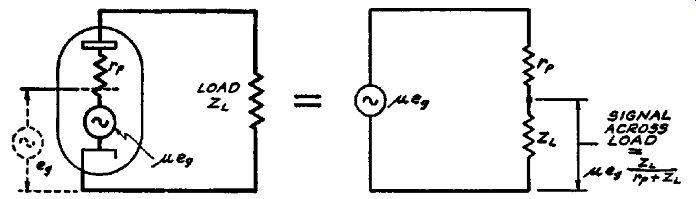
Fig. 2-8. A triode used as an amplifier can be considered as being equivalent
to a generator in series with an internal resistor equal to the plate resistance
of the tube. The manner in which the signal voltage divides between the internal
plate resistance and the load impedance is shown at the right.
... signal voltage equal to p. times the signal voltage at the grid. The internal plate resistance of the tube becomes the internal resistance of the generator. Thus if a tube is rated at an internal plate resistance of 20,000 ohms and a p. of 10, the generator form of representation would bear the constants of 20,000-ohms internal resistance and of 10 volts output voltage. Working along such lines we can say that the simple triode amplifier circuit of Fig. 2-3 finds its equivalent in the generator circuit of Fig. 2-8, wherein 11-eir is the output voltage, r_p is the plate resistance and FL is the load resistance.
Suppose that we investigate the various voltage relations which exist in this equivalent circuit of a triode amplifier. The load can be assumed to be a resistor, such as would be found in a conventional resistor-coupled audio amplifier. However, what will be said about voltage distribution is true regardless of the form taken by ZL, At the present moment it is far more important to consider the effects of various values of load rather than the effect of the different types of load. The problem at hand is to establish what portion of the maximum voltage available in an amplifier tube will appear across the tube load; in other words, what portion of ue_g in Fig. 2-8, will appear across ZL, You will note that the load is in series with the internal resistance r_p and that the total signal voltage is available across this series combination. This means that the signal voltage across the respective resistances (or impedances) will divide in accordance with their respective values. The ratio ...
ZL load impedance r_p + ZL = plate resistance+ load impedance
... expresses the fraction of the total signal voltage which appears across ZL.
As is evident, when ZL = r_p, the full signal voltage divides equally between the two resistances, and thus one way of securing the maximum signal-voltage drop across ZL is to make the load many times the value of r_p. The higher the value of ZL with respect to r_p, the greater is the amount of amplification actually realized in a voltage-amplifier stage and the smaller is the signal voltage lost across the internal plate resistance r_p, However, the value of r_p is a determining influence in establishing what portion of the available signal voltage will be obtained across the load, because if we set 10X r_p as being a satisfactory value for ZL so as to obtain about 90 percent of the available signal voltage, this is practical only when r P does not exceed about 50,000 ohms.
The higher the value of r_p, the higher must be the value of ZL and consequently the greater must be the B-supply voltage so as to provide the required voltage at the plate of the tube. This is a limitation which plays a very important part in the actual d-c resistance value of ZL. In fact, it is a general limitation, and you will find that the majority of voltage amplifiers employ a ratio between the load impedance and the internal plate resistance such that approximately fifty percent of the maximum possible amplification is obtained.
To summarize what has been said, it is evident that in a voltage· amplifier the higher the load impedance with respect to the internal plate resistance, the greater is the amplified signal voltage developed across the load. This can also be expressed by saying that the greater the load impedance with respect to the internal plate resistance, the greater the amplification obtained in the stage.
Let us now examine this arrangement with respect to frequency. Suppose that ZL is a winding of some kind, the primary of an audio transformer or a choke. How does this affect the signal transfer from the tube to the load with respect to frequency? Naturally, it is going to vary, depending upon the frequency of the signal voltage and the impedance of the load at that frequency. The higher the impedance of the load at any one specific frequency, the greater the signal voltage developed across the load with respect to that lost across the internal resistance r_P. Naturally the reverse is also true; the lower the impedance of the load at any one frequency, the lower the signal voltage transferred and the lower the amplification in the stage.
Thus if the frequency of the signal voltage varies and the load impedance is of such character as to vary with frequency, the signal voltage developed across the load impedance will vary with frequency. As to the amount of amplification obtained in such a voltage amplifier system, the following equation applies:
A l
.fi . ZL mp i cation = p. + Z Tp L
From what has been said so far it is obvious that some value of signal voltage will be developed across the load impedance, no matter what its value, provided it is greater than zero; but whether or not the signal voltage so obtained is what it should be depends naturally upon the conditions in the circuit. For example, if some condition exists which tends to reduce the load impedance to a very low value, then only a very small signal will be present across the load.
Such a condition might arise in the case of a tuned r-f trans former used in conjunction with a triode tube. In other words Zt might be a tuned r-f plate winding, the load impedance being supplied by this winding and parallel resonance being used to develop a high value of impedance at resonance. At resonance, a signal voltage drop would develop across the tuned winding; hut if the tuned circuit were not resonated to the frequency of the signal voltage, the impedance would be low and the signal voltage drop across the winding would be correspondingly small.
Amplification in Tetrodes and Pentodes
All voltage amplifiers are not triodes. Tetrodes and pentodes also are used very extensively, and while the basic facts as out lined herein concerning the transfer of the signal from the tube to the load are not changed, the method of calculating the signal transferred from the tube to the load is different. This is brought about by the fact that the plate resistance of tetrodes and pentodes is very much higher than that of triodes, in fact very much higher than the usual load impedance. As a result the signal current which flows in the plate circuit has a constant value regardless of the load impedance used.
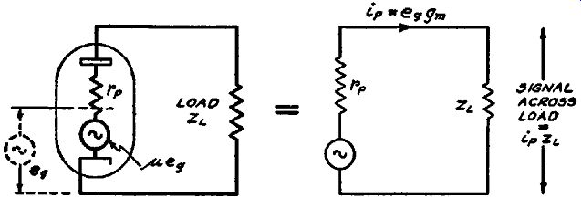
Fig. 2-9. In screen grid tubes, the internal resistance is so high that the
same value of current flows through the load regardless of the value of load
impedance.
Instead of calculating the voltage across the load impedance in terms of the relative drop across the load impedance and the internal plate resistance, it is convenient to make use of this fact that a constant signal current will flow in the plate circuit as the result of a signal voltage applied to the grid. This you will recall is expressed by the mutual conductance which gives the change in the plate current per unit change in the grid voltage.
Knowing the magnitude of signal current per unit signal voltage on the grid, we can easily establish the signal voltage developed across the load impedance, which then equals the actual amplification being obtained. The generator equivalent of the pentode is shown in Fig. 2-9, and as you can see it is virtually identical to that of the triode shown in Fig. 2-8. The only difference is that the signal component of the plate current is not affected by the load impedance because the plate resistance is large in comparison with the load impedance. Referring to Fig. 2-9, it is clear that the signal plate current i_p, is equal to u-eg/rp, which in turn is equal to eggm since the mutual conductance is equal to µ./rp, The signal voltage developed across the load can be computed readily by multiplying the value of signal current by the load impedance. Thus the signal across the load is equal to eggmZL and the amplification is equal to the product of g_m and ZL, The larger the mutual conductance, the greater is the amplification; and similarly, the larger the load impedance the greater is the amplification.
In computing the amplification as explained in the preceding paragraph, it is important that the mutual conductance and plate impedance be expressed in the proper units. A convenient set of units to use is to express the mutual conductance always in micromhos (microamperes per volt) and to express the load impedance in megohms. The amplification will then be equal to the product of g_m and ZL expressed in these units.
The following example will make this clear. Suppose we take the case of a 6K7 which is working into a parallel resonant tuned circuit. If a signal is applied to the grid at the resonant frequency of the tuned circuit, then the tuned circuit will act as a resistance of say 50,000 ohms. This value is commonly found in intermediate-frequency amplifiers. Thus the load impedance for the tube is 50,000 ohms or .05 megohm. The mutual conductance of a 6K7 is about 1400 microamperes per volt. Hence the amplification is equal to 1500 x .05 or 75.
The illustration employed for the pentode is applicable to the tetrode without any change and for that reason we show just the pentode. As you can see, the higher the load impedance, the greater is the actual voltage developed across the load impedance, or the greater is the amount of amplification obtained with the stage. The fact that the tetrode and pentode circuits are more complicated does not alter matters. All that was said with respect to frequency of the signal voltage and variation in load impedance is applicable to the pentode and tetrode as well as to the triode.
Series and Parallel Connection of Load Impedances
Up to the present time we have spoken about signal transfer between the tube and its associated load with respect to the amount of amplification obtained in the stage. In the two illustrations showing the triode and the pentode, the load impedance was so wired into the circuit that it carried the d-c as well as the a-c components of the plate current. Lest this type of connection, which is called series feed, be accepted as standard with out any alternative, we want to devote some space to a short discussion of parallel-feed arrangements which make use of a shunt connection of the load device.
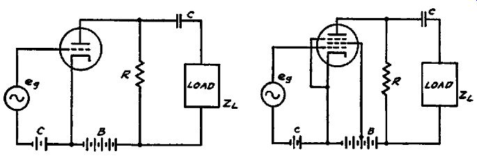
Figs. 2-10, 2-11. A triode, left, and pentode amplifier stage, right, using
a parallel or shunt feed arrangement of the load. No d.c. flows through the
load.
In many instances the design of the circuit is such that the d-c component is not desired in the coupling unit or load device. In other words, the nature of the unit used as the load impedance is such that better results are obtained if only the a-c or signal component of the plate current flows through the unit. Such is occasionally the case in audio amplifiers. Then again certain r-f and i-f circuit arrangements are improved if the load impedance or coupling device is not subjected to a d-c voltage. To accomplish these ends, shunt feed is used as shown in Figs. 2-10 and 2-11.
These two illustrations are very much like Figs. 2-6 and 2-7.
The essential difference is the fact that the load circuits in each case are connected in shunt with the device which feeds the plate voltage to the tube, and the load devices are isolated from the d-c supply by means of a blocking condenser C. As to the device which completes the d-c path in the plate circuit, it is not always the resistor R shown in Figs. 2-10 and 2-11. In some instances this unit is a choke.
No special comment is made concerning the nature of the load impedance. They can be of any type in common use without in any way altering the fact that such circuit arrangements are known as shunt feed and only the a-c or signal component of the plate current flows through the load. However, it is very significant to note, in view of what will follow later, that the resistor R carries both the d-c and a-c components of the plate current, and hence a signal voltage drop takes place across R as well as across the load ZL, As a rule, the design of such circuits naturally provides for the maximum signal voltage drop across the load ZL. As to the relation between the load impedance, the tube plate resistance, and the amount of amplification obtained, the use of shunt feed does not change the computations or the process of operation. However, what must be remembered is that the impedance of the feed circuit, in these two cases the resistor R, is in shunt with the load and therefore influences the final value of impedance present in the plate circuit.
Signal Distribution In Voltage Amplifiers
Having covered the preliminaries relating to amplification and the manner in which the signal is transferred through the tube to the coupling device, we are now ready to speak about the distribution of the signal in a voltage amplifier stage. What happens to the signal during the process of amplification? Where in a voltage amplifier does this signal exist? The answers to these questions will show the process of signal tracing and the possible means of isolating a defect in a voltage amplifier stage by means of signal tracing.
Inasmuch as there are many types of voltage amplifiers, types which differ because of the kind of coupling device used between stages, it would seem necessary to deal with several systems.
There are of course certain definite similarities between all of these amplifiers because after all is said and done, the tube structure is the same in all types of amplifiers which employ the same tube. However, we do find sufficient differences in certain types of coupling devices to require recognition and discussion.
In order to present the subject properly it is essential to consider an amplifying stage from two angles: First, the basic amplifier circuit without any by-passing; and second, with all of the additional components added. By so doing we can best investigate the path of the signal and present the subject in such a manner as to enable the simplest interpretation of conditions existing in all types of voltage amplifiers.
Radio-Frequency Voltage Amplifiers. Let us start with the triode used in a single tuned-radio-frequency stage. True, such amplifiers are now no longer made, but many are still in use. The basic schematic of such a system is shown in Fig. 2-12. The signal voltage e1 is fed into the input circuit of the tube. The coupling device is a conventional radio-frequency transformer with tuned secondary. The amplified signal which would normally be fed to the succeeding amplifier stage normally appears across the terminals of the tuned secondary circuit and we designate this signal voltage as e2• We shall assume for the sake of illustration that the frequency of the signal is 1000 khz.
Fig. 2-12. A triode used as a radio-frequency amplifier. The amplified output
signal appears across the tuned secondary winding.
The control grid bias for the tube is secured by means of a cathode bias resistor identified as Re, The plate voltage is se cured from a power-supply unit. As you well know, the voltage divider employed in such power-supply units is a resistor and this resistor is identified as R8 with the positive and negative terminals as shown. Take note of the fact that all by-pass condensers have been omitted. This is deliberate at this time in order to show later, after the by-pass condensers have been added, how the path of the signal currents is changed and what happens to various signal voltage drops in the circuit.
Let us now trace the path of the plate current in this circuit.
It is through the primary winding of the transformer, through the tube from plate to cathode, through the bias resistor and through the B supply. As to the respective d-c voltage drops across these various resistances, they mean very little to us be cause we are not concerned with d-c voltages. However, what does interest us is that if the signal e1 is introduced, the plate current will contain an a-c as well as a d-c component. Thus when the signal is applied, we find that an a-c or signal voltage drop appears across all of the devices which carry the d-c plate current. As is to be expected, the frequency of these signal voltages which appear across the various resistances in the circuit is the same as that of the input signal, or 1000 khz. However, in connection with this signal-voltage drop, we must comment upon the r-f transformer primary. The impedance of this winding by itself is very low, so that the signal voltage drop at 1000 khz across P would be very small. However, when we consider the primary winding as a part of the tuned transformer and the secondary winding is tuned to the signal at 1000 khz, an entirely different condition is created.
The entire transformer, primary and secondary windings now act as one, so that an effective impedance appears in the plate circuit of the tube, an impedance which is many times greater then the impedance of the primary itself. In other words, the condition of resonance in the secondary of the r-f transformer makes the entire transformer act as a high impedance present in the plate circuit, so that a substantial signal voltage will appear across the primary of the transformer. Let us for the moment say that the effective impedance of the primary is equal to 10,000 ohms.
What is the status of the signal voltages in Fig. 2-12? Since the signal currents flow through all of the components, a signal voltage will be developed across the r-f transformer primary. In addition a signal voltage will be produced across the power supply voltage divider R_B and also across the cathode bias resistor R_c.
How do these conditions affect our operations? In the first place it is important to remember that the major objective is to secure the maximum signal voltage across the load impedance, in this case the r-f transformer. Second, we must minimize all signal-voltage drops other than that across the load impedance, so that the maximum signal will be obtained across the load impedance. This means that the signal-voltage drop across the bias resistor R_c must be kept at a minimum and the signal voltage drop across the power-supply resistor R_B must also be kept at a minimum. If this is done, then the available signal voltage will divide between the internal plate resistance and the load impedance.
Now, since no means for minimizing or eliminating the signal voltage drop across certain portions of the amplifier have been incorporated, we find that with the ground as the reference point, a signal voltage will exist between ground and the cathode. A signal voltage will also be found between ground and the plus end of the B-voltage supply or the low end of the r-f transformer primary. Naturally signal voltage exists between ground and the plate of the tube. Of all these signal voltages, that which is available across the terminals of the r-f transformer primary is the only one of use to us. In each case the magnitude of the signal voltage is equal to the value of the a-c component of the plate current times the impedance of the element through which this signal current flows.
Assuming that the aforementioned signal voltages exist, what is the effect of their presence? Are they harmful at any point? Do they afford certain information? What can be done to minimize those signal voltages which are not required? Let us answer these questions in the order in which they are given. The effect of signal voltages in circuits or across devices where they do not belong cannot be stated as being harmful in every instance, be cause that condition which might be stated as being undesired in one case, might be actually wanted in the next. For example, the signal voltage which is built up across the cathode bias resistor is at times desired and then at other times it is entirely un wanted. For the present moment let us assume that it is not wanted and see what happens.
If you recall what was said concerning the effect of the grid voltage upon the plate current, you can readily understand that since the grid is located between the cathode and the plate, a definite relation exists between the voltages on the grid and those on the cathode. If, for example, a signal is applied which at any instant makes the grid less negative and results in an increase in plate current, this increased plate current naturally flows through the cathode circuit. Since the cathode circuit contains the resistor Re, an increased voltage drop takes place across this resistor and the cathode becomes more positive with respect to the grid. This tends to offset the change in voltage of the grid because the net difference in voltage between the grid and the cathode is reduced.
If during the operation of an amplifier an a-c signal voltage is applied to the grid, causing a change in plate current in accordance with this change in grid voltage, and the development of a corresponding signal voltage is permitted across the cathode resistor ,-then this signal voltage across the cathode resistor will tend to offset some of the signal voltage applied to the control grid of the tube. Expressed differently, the signal voltage developed across the cathode bias resistor by the a-c component of the plate current is out of phase with the signal voltage applied to the input of the tube, and hence a degenerative condition is created. This degenerative condition tends to reduce the signal output from the amplifier because it tends to reduce the effective signal between the control grid and the cathode.
The elimination of such a degenerative condition is simple. It means the removal of the signal voltage developed across the cathode bias resistor. It stands to reason that this cannot be accomplished by removing the cathode bias resistor, for if this is done, it becomes impossible to obtain the required d-c bias.
Hence the solution must be some means whereby the impedance of this cathode bias resist-or is reduced to a minimum without altering its d-c resistance. The answer is a by-pass condenser connected across the cathode bias resistor as indicated by C1 in Fig. 2-13.
The value of this condenser C1 is such that its reactance over the range of frequencies of e1 is very low in comparison with the d-c resistance of the cathode bias resistor. Thus while the correct bias is developed across Re by the steady component of the plate current, a very low impedance path is offered by CJ to the a-c or signal component of the plate current and the degenerative voltage built up across the condenser is negligible.
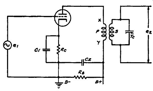
Fig. 2-13. A triode used in a radio-frequency amplifier stage. Note the condensers
which are used to by-pass the cathode and plate-supply circuits.
It is of course true that the magnitude of signal voltage built up across the cathode bias resistor when the by-pass condenser is absent is ordinarily not very great, but it is still sufficiently great to be used as an indicator to establish that there is improper by passing caused, for example, by an open-circuited by-pass con denser, or one which has such a high internal resistance that its by-passing effect is not very good. Normally the average by-pass condenser has such a low reactance at the normal run of signal frequencies, that the cathode is virtually at ground potential with respect to the signal. Thus a test for the signal voltage between ground and cathode is a test for the condition of the by-pass con denser which is connected across the bias resistor. Any such signal voltage test between ground and cathode would be made at the frequency of the signal voltage fed into the tube, namely the frequency of e1. What has been said should not be construed as being limited only to radio-frequency amplifiers. It is just as true in inter mediate-frequency and in audio-frequency amplifiers. At the same time, examples can be found wherein this by-pass condenser is deliberately omitted in all of the classifications of amplifiers named.
It is also significant to note that the conditions described are not limited to triodes. Perhaps it is premature, in view of the fact that tetrodes and pentodes will be mentioned later, but it can be said that the significance of signal voltages between cathode and ground in triodes is similar in screen grid tubes.
We have spoken about the development of a signal voltage across the internal impedance of the power supply. What is the effect of signal voltage across this impedance? As stated earlier, it reduces the voltage which can be effective across the normal load impedance because it tends to reduce the magnitude of signal plate current flowing in the plate circuit. How can this be over come? By inserting a low-reactance path across the B supply; in other words, by-passing the plate circuit so that the a-c or signal component of the plate current finds an easy path around the B-supply unit. This path is provided by the by-pass condenser C2 in Fig. 2-13. The reactance of this condenser, being very small in comparison with the impedance of the power sup ply, places the low end of the r-f transformer primary at ground potential as far as signal voltages are concerned. Thus a test for the signal voltage between ground and the low end of the r-f transformer will establish whether the by-pass condenser C2 is functioning.
A supplementary condition associated with the plate by-pass condenser requires mention. When a number of stages of amplification are operated from the same plate power supply, the impedance presented by this power supply is naturally common to the plate circuits of all of the stages. If, as a result of improper by-passing, a substantial signal voltage is permitted to build up across this common impedance, it is very apt to cause regenerative interaction between the stages and possibly oscillation of the amplifier.
Returning again to Figs. 2-12 and 2-13, a summary of signal conditions in these circuits shows the following: As a result of normal operation and with normal precautionary measures instituted, the input signal e1 appears at the control grid between grid and ground. In fact all signal voltages are most conveniently measured with respect to ground. An amplified signal should of course be present at the plate; a test between plate and ground is the equivalent of a test across the terminals X and Y of the primary winding because C2 effectively places point Y at ground potential. The signal is also present across the secondary terminals of the r-f transformer. If all conditions are correct, there will be no signal at the cathode or at the B-plus end of the trans former primary.
As to the signal voltage between plate and ground or across the primary of the r-f transformer, two conditions must be mentioned. While it is true that we show a triode amplifier, wherein it was customary in the past to employ r-f transformers with very low-impedance primaries and wherein the signal voltage appears across the primary only when the secondary is properly resonated, it is necessary to mention that if the primary of this r-f transformer were of the high-impedance type, a maximum signal would exist across the primary winding when the secondary is resonated, but a certain amount of signal voltage would still exist across the primary when the secondary was detuned. The difference between the two conditions is at all times sufficient to be able to distinguish when the secondary is in or out of resonance with the input signal. The reason for the existence of such a signal across the primary when the secondary is off resonance is that the impedance of the primary itself is substantially high.
In the case of the low-impedance primaries, there would be practically no signal at the plate off resonance because the low impedance primary would be almost a short circuit as far as the signal is concerned.
As to the signal e2, shown across the secondary terminals of the r-f transformer, this naturally is a maximum when the secondary circuit is correctly tuned and decreases rapidly for an off-resonance state, eventually reaching zero. The rapidity of decrease of the signal voltage across the r-f transformer secondary depends upon the selectivity characteristics of the transformer. The more selective the transformer, the more rapidly will the signal voltage across the secondary winding reach zero as the circuit is tuned off resonance with the frequency of the input signal.
The use of a tetrode or pentode tube in place of the triode does not alter the comments made in connection with the triode. All that happens is that the added tube elements increase the complexity of the circuit and introduce one or more additional circuits which are subject to the signal test. For example, Fig. 2-14 shows the pentode tube used as an r-f amplifier. The circuit structure is very much like that of Fig. 2-13, except for the added tube elements and the fact that the screen-grid circuit contains another by-pass condenser, C3. This capacity C3 places the screen at ground potential with respect to the signal and in this way removes the possibility that the signal component of the screen current will cause the development of a signal voltage across the impedance of the B supply. Thus the presence of a signal voltage between the screen grid (point Z) and ground, ...
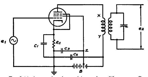
Fig. 2-14. A pentode tube used in a r-f amplifier stage. Condensers are used
to by-pass the cathode, screen, and plate supply circuits in order to prevent
the development of signal voltages at these points.
... establishes that proper by-passing is not being accomplished.
All other statements concerning the signal in the control grid, cathode, and plate circuits in triodes apply to the pentode and tetrode tubes. Since the tetrode is similar in circuit structure to the pentode, except for the omission of the suppressor grid, it is not necessary to show a schematic of the tetrode r-f amplifier.
Making the amplifier more complicated by the use of filter networks so as to confine the signal currents to certain paths, does not in any way alter any of the statements made so far. For example resistance-capacity filters are shown in a pentode stage in Fig. 2-15. R3 is the plate-circuit filter resistor and R2 is the screen-circuit filter resistor. The respective by-pass condensers are C3 and C2. The process of amplification remains unchanged.
The signal test points remain the same as before, namely the control grid, the plate, and points Y and Z to establish whether the low-impedance paths to ground for the signal component of ...
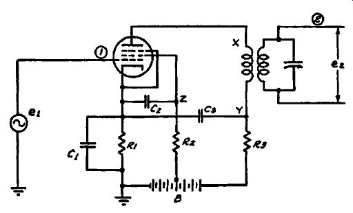
Fig. 2-15. A pentode tube used in a r-f amplifier stage. Resistance-capacity
filters are used to pre vent the screen and plate circuits from developing
signal voltages at the power supply.
... the screen and plate currents are functioning properly. The fact that the by-pass condensers C2 and C3 join the cathode instead of connecting directly to ground is unimportant since the condenser C1 provides the required low-impedance path from cathode to ground.
As to operating voltages, the presence of filter resistors and condensers increases the possibilities of incorrect operating voltages, due either to some variation in the values of R2 and R3 or to leakage in the condensers C2 and C3. Leakage in the screen and plate by-pass condensers, with the connections shown, will increase the operating bias and in that way reduce the amount of amplification obtained with the stage. However, if proper signal amplification is obtained, it is reasonable to assume that the operating voltages in the stage are correct.
Changing the type of load impedance does not in any way alter the distribution of the signal in an amplifier stage. For example, Fig. 2-16 shows a typical i-f amplifier stage in which the signal is provided by a tuned input circuit, the secondary of T1. The plate winding is tuned and the secondary of TS also is tuned and feeds the succeeding amplifier stage. The remainder of the circuit is very much like those shown in preceding illustrations.
As far as actual operation of the amplifier tube itself is concerned, the principal item is the operating voltages, but as far as operation of the amplifier stage with respect to the signal is concerned, we find that the signal from T1 is important and the signal developed in T2 is important. Assuming that T1 is properly resonated to say 470 khz, the signal which is supposed to be amplified, this signal is present across the secondary circuit between the control grid and ground. However, you should remember that this signal will be present even if the amplifier tube is entirely inoperative because of any one of a number of reasons.
As long as the input transformer circuit is complete and there is no short circuit, the signal will be present across the grid-to ground circuit.
As to the amplified signal in the plate circuit, that is, between plate and ground in Fig. 2-16 or between X and Y in the same illustration, it depends upon the tuning of the resonated primary winding. Whether or not it appears across the tuned winding, depends entirely upon the impedance of this winding. As stated before, since parallel resonance is used, the impedance is a maximum at resonance and falls off on both sides of resonance. If the circuit is badly de-tuned, very little signal voltage will be present in the plate circuit. For example, in a typical case where an i-f stage using a pentode was checked, a maximum signal voltage existed when the transformer was tuned to 470 khz. When the transformer was detuned by 5 kilocycles, the signal voltage between X and Y dropped by 50%. When the transformer was detuned by approximately 20 kilocycles, the signal voltage dropped to only 5% of its original value.
It stands to reason that any condition of incorrect resonance in the primary circuit will influence the signal in the secondary circuit. Thus if the primary is greatly mistuned, very little signal will be produced across the secondary. Possibly there might be some signal due to stray signal pickup, but this is very much less than would exist when the transformer is properly tuned.
Speaking about the signal present in the output circuit, it stands to reason that under normal conditions the frequency of the signal in the plate circuit is the same as that applied to the grid circuit. Furthermore, under normal conditions, the character of the signal in the plate circuit corresponds to the signal applied to the grid circuit. Thus if a modulated carrier of 470 khz, 1000 khz or 30,000 khz is applied to the grid circuit, the signal in the plate circuit will be 470 khz, 1000 khz or 30,000 khz, respectively, and it will retain the modulation characteristics of the signal fed into the grid circuit.
These examples of frequency are purely illustrative. In practice they can be lower or higher, as for example in the commercial band just above the audio band, or in the television band. Furthermore the character of the signal is of no consequence as far ...
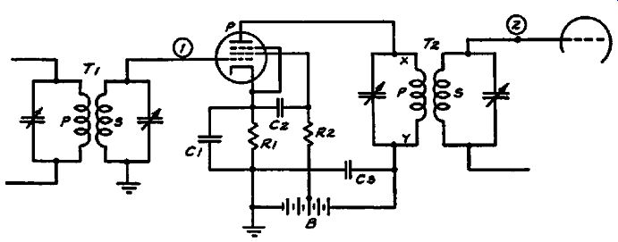
Fig. 2-16. An amplifier stage with both the input and output circuits tuned.
The dependence of signal transfer upon the tuning of these circuits is described
in the text.
... as amplifier operation is concerned. Possibly one type of signal might be more difficult to check than another, but neglecting the testing procedure for the moment, what has been said concerning the distribution of the signal remains unchanged. For example, if e1 is a conventional unmodulated carrier, the distribution of the signal through the amplifier is exactly the same as if the signal were an amplitude-modulated carrier or a frequency-modulated carrier. The exact method of establishing the presence or the level of the signal at various places might be more complicated with one type of signal than with another, but the distribution remains the same and the test points remain the same.
Amplification in Tube and Transformer
We have spoken about the tube as an amplifier, but actually the tube itself does not constitute a complete stage of amplification. It is a part of the stage, but the entire stage of amplification includes the output coupling unit. This means that if we consider the schematic of Fig. 2-16 as a typical example, the amplification of the stage is that which exists between the control grid of the tube, point 1, and the grid of the succeeding tube, point t, in Fig. 2-16. These references to test points mean that the test is made between these points and ground in each case.
With reference to the distribution of gain or amplification in a complete stage of this type, it is divided between the tube and the coupling unit. As a general rule, the modern receiver is of such design that very little if any gain is obtained in the coupling unit, that is, in the interstage r-f or i-f transformer. The gain usually is obtained between the grid and plate of the tube. The coupling device enables the transfer of the signal from the plate to the grid and also provides selectivity.
However, in the older receivers employing triode tubes, the gain was divided between the tube and the coupling unit, so that both contributed the final amount of amplification. The exact distribution of gain between the tube and the coupling unit does not justify detailed discussion, if only because so few of such receivers are in use, but at any rate we can say that the tube contributed very little to the overall stage gain. Practically all of the voltage gain was provided by the transformer because of the step-up ratio between the primary and the tuned secondary winding. Thus if you refer to Fig. 2-12, the level of the signal at the control grid and plate would be about the same, whereas the signal voltage e2 across the secondary of the r-f transformer would show the increased voltage as a result of the gain in the transformer. It is of course possible that in certain particular instances, the gain obtained in the tube would be greater than unity, but by and large the majority of these stages operated in such manner that most of the amplification was obtained in the transformer.
When tetrode or pentode type tubes are used as r-f and i-f amplifiers, we find that just the reverse of what has been said about triode amplifiers is true. Practically all of the gain is obtained from grid to plate, so that at resonance the signal at the plate of the tube is greater than the signal at the grid of the tube by practically the amount of gain provided by the stage. As far as the transformer is concerned, the signal level at the plate of the tube and the signal level at the grid of the succeeding tube or point 2 in Figs. 2-15 and 2-16 is approximately the same if not a slightly lower. In other words, the gain through the transformer at resonance is approximately one. This applies to r-f as well as i-f transformers.
These details relative to gain in r-f and i-f transformers with triodes, tetrodes and pentodes are extremely important in signal tracing, because as you can see the normal conditions differ in accordance with the type of tube used. There are two points of difference in r-f and i-f amplifier systems which should be mentioned at this time, if only briefly, because they are discussed at greater length in a separate section. We are referring to the antenna transformer and the transformer which couples the last i-f stage to the diode detector. For the present let it suffice to say that a definite amount of gain is available in the average antenna transformer and that this gain varies with the class of receiver in which it is used. Also, the i-f transformer which feeds the diode usually shows a loss in voltage, that is, it acts as a step-down instead of a step-up transformer.
Audio-Frequency Amplifiers
The distribution of the signal in an audio-frequency amplifier system is the same as in a r-f or i-f amplifier, with the exception of course that the signal frequency is lower. True, the general structure of the circuit is slightly different, occasioned by the fact that audio-frequency coupling devices are used, but when we consider the tube alone, it still remains an amplifier and when we add the coupling unit, that which is in the plate circuit is still the load impedance. For example, in Figs. 2-17 and 2-18, we show a resistance-capacity coupled triode and pentode stage respectively.
The audio signal e_1 is present across the grid leak R1, which means that it is present between the control grid of the amplifier tube and ground. This signal is assumed to originate someplace ahead of the blocking or coupling condenser C1. The plate current during amplification contains the signal component which has the same frequency as el' Since this plate current flows through the bias resistor R2 and since it is desired to develop only a d-c voltage (the bias) across this resistor, the by-pass condenser C2 is made sufficiently large so that it offers a low impedance path to the audio signal. As you can readily under stand, the capacitance of such a by-pass condenser must be greater when working with audio frequencies than with radio or intermediate frequencies.
In connection with such bias resistor by-pass condensers, the amount of by-passing accomplished is not always sufficient to …
FIG. 2-17. A triode amplifier stage using resistance- capacity coupling. R3
is the plate load across which the amplified signal voltage is developed.
… prevent entirely the development of an audio signal across the cathode resistor; this means that under certain conditions, particularly at low audio frequencies, a signal will be observed between the cathode and ground. In connection with. the audio signal developed across the cathode resistor, some amplifiers deliberately omit the bias resistor by-pass condenser in order to secure a definite amount of degeneration. In such cases a strong audio signal is present across the cathode resistor. In other cases you might find that this bias resistor is made up of two units, one of which is by-passed and the other is not. That which is not by-passed is intended to develop an audio signal for degenerative purposes or for deliberate feedback to some other portion of the amplifier. Examples of such feedback will appear later in this volume.
As to the signal in the plate circuit, the signal current flows through the load resistor R3 and a signal is developed across this resistor, so that a signal exists between the plate and ground.
The by-pass condenser C4 serves the same purpose in an audio stage as the plate-supply by-pass condenser in an r-f or i-f amplifier.
Whatever the signal voltage developed across the load resistor RS, that signal voltage also appears across R4, which is the grid …
FiG. 2-18. A pentode amplifier stage using resistance-capacity coupling.
The distribution of signal voltages is described in the text.
… leak for the succeeding stage. The blocking condenser C3 serves the purpose of keeping the d-c voltage at the plate of the amplifier tube from reaching the grid of the succeeding tube. Its value is such that it ordinarily does not attenuate the signal, so that in amplifiers of this type, the signal level at the control grid of the following tube, point 3, is virtually the same as the signal level at the plate of the preceding tube, point S in Fig. 2-17.
Speaking about attenuation or reduction of signal level, such amplifiers do show a marked drop at the low frequencies, due to the increased reactance of the blocking condenser C3. At the higher frequencies the amplification also drops off as a result of the shunting effect of the tube and wiring capacitance. Usually, designers try to arrange the constants of these components in such manner that the amplification is substantially flat over the entire audio range. This matter of attenuation is more important when overall frequency response is being considered than when a single-frequency test signal is fed into the amplifier. As far as the actual value of amplification is concerned, this depends upon a number of different factors such as the type of tube, the load resistance, the coupling or blocking condenser and the grid leak used for the next stage. However, since we are concerned solely with amplifiers already designed, we need not discuss the part played by each of these components.
The use of tetrode or pentode tubes in place of the triode does not essentially alter the operation. All that happens, for example in the circuit of Fig. 2-18, is that the added tube elements increase the number of connections and the number of components in the circuit. The signal distribution in the system is in line with what has been said before about pentodes used as voltage amplifiers. The test points shown in Fig. 2-18 correspond with the numbers shown in Fig. 2-17, with the addition of the screen grid.
Speaking about the screen grid in the pentode tube, it is interesting to note that if the screen circuit is not by-passed, a signal voltage will be present at the screen grid, between the screen grid and ground. The signal voltage applied to the control grid will cause a signal component to be present in the screen current and this will develop a signal voltage across whatever impedance or resistance may be present in the screen circuit. In this instance, it would be resistor R5.
As to the distribution of gain in such audio amplifiers, all of it is provided by the tube. The coupling unit, in this case R3-C3-R4, contributes nothing. Nevertheless, when considering the total amplification provided by such a stage, it is determined by the increase in signal between e1 fed into the control grid of the tube and e2 available across the grid leak of the succeeding tube.
Fig. 2-18 contains a variation in the plate circuit. Although shown only in this schematic, it is used not only with pentode tubes but also with other types of voltage amplifiers. We are referring to the use of the plate-circuit filter resistor R6. RS is in series with R6 as far as the steady plate current is concerned, but as far as signal current is concerned, only R3 acts as the plate load. This is true because the by-pass condenser C6 provides a low-reactance path to ground, a path which does not include RG and the plate power supply. If, however, C6 were open-circuited or for some reason did not perform its by-passing function, then the plate load would be the sum of the two resistances RS and R6.
With operation normal no signal voltage is present at X, the junction of RS and R6; but if C5 is open, a signal voltage will be present across RS and between X and ground. This would also be true if RS were a choke and R6 a resistor.
Fig. 2-19. A triode amplifier stage using transformer coupling in the load
circuit. Signal voltages are present at points 1, 2, and 3.
Variations of circuit components used in voltage amplifiers do not alter the process of amplification. For example, the grid leak RJ, the plate load R3 and the grid leak R4 need not be resistors. They can be chokes such as are used in impedance capacity coupled amplifier systems. As far as that is concerned, the system shown in Fig. 2-18 need not be used for audio amplification. It can just as readily be used at higher frequencies with chokes replacing the various resistors or different combinations of chokes and resistors. While it is true that the type of component utilized as the coupling device can change the number and location of the signal test points, replacement of a resistor by a choke in an amplifier system does not introduce variations in the basic operation of the tube or in the distribution of the signal.
Of course the type of coupling unit will influence the magnitude of signal at various points in the system. Thus in the trans former-coupled amplifier stage shown in Fig. 2-19, the essential difference between this circuit and that of Fig. 2-17 is in the output coupling device. Whereas in Fig. 2-17, the signal level is the same at the plate and the succeeding grid, in Fig. 2-19 the signal level at point S, the succeeding grid, is usually greater than at point 2, the plate of the amplifier, because of the step-up in T1. As you can see, proper interpretation of signal distribution must be accompanied by an understanding of the function of the various components with respect to the signal. This subject of functions of various types of coupling devices and their relation to signal level and signal distribution is dealt with in detail in the section devoted to coupling devices.
FIG. 2-20. Various methods of coupling the signal can be used in the input
and output circuits. In this stage, choke coupling is used in the input and
choke-transformer coupling in the output circuit.
Examples of variations of these basic circuits are shown in Figs. 2-20 and 2-21. Various combinations of input and output coupling devices are shown. In each case, you will see that the basic circuit remains the same and hence the operation of the amplifier is the same. Likewise the basic signal test points re main unchanged. Where the number of components is greater, the number of test points is greater; however, certain points remain common to all systems because they are an integral part of the basic tube circuit.
Defective Amplifier Operation
Up to this point we have spoken about the correct operation of voltage amplifiers and the appearance of the signal at certain designated test points. What happens in an amplifier when the operating conditions are incorrect? How does the character of the signal change?
Suppose that we analyze first the possible changes which may take place in a modulated carrier--changes that would be noted by a person listening to a receiver and who then would say that some defect has developed in the system. Naturally the person would not be able to identify the exact fault; all he would know is that the signal no longer was normal. It is up to us to see what conditions are responsible for the final result and where changes from normal conditions can be observed and in what manner they can be noted.
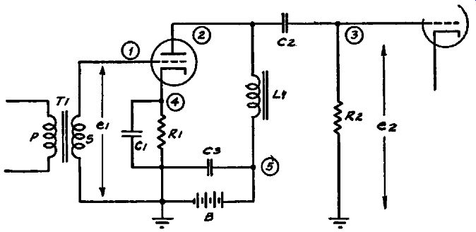
FIG. 2-21. A triode amplifier stage showing the use of transformer coupling
in the input circuit and choke coupling in the output circuit.
Distortion of a signal may take place in various ways and be come apparent in a number of different ways. The exact nature of the distortion, with possibly but one exception, is of very little interest to us; for after all, the primary object is the correction of the distortion, rather than an exact analysis of its nature.
Of course the correction of the abnormal signal requires that the condition responsible for this type of signal be corrected, but that is not a major problem .... The problem is the determination of the cause of this condition.
We previously mentioned hum as a possible exception to the general statements made herein. Now, there are a number of places where hum can originate, but since we are now concerned with the process of amplification, we need consider at this time only those conditions which cause hum in connection with a stage of voltage amplification. It is of course true that those conditions which will cause hum in a voltage-amplifier stage also will cause hum in a power-amplifier stage, so that what is said here can be kept in mind for future reference.
One item which is of interest if only because it is generally difficult to solve, is hum due to cathode-heater leakage in the indirectly heated type of tube. In high-frequency circuits this type of defect may modulate the carrier and thus become noticeable, whereas in audio-frequency amplifiers, it becomes a part of the signal. Basically it is due to the presence of a small leak age current which flows between the heater and the cathode and therefore flows through the cathode bias resistor. Being of low frequency, it is often inadequately by-passed by the cathode by pass condenser and consequently builds up a hum voltage across the cathode resistor; this tends to vary the voltage between cathode and control grid and therefore creates a hum signal component in the plate current. A diagram of this condition is shown in Fig. 2-22.
There are a number of other conditions associated with the heater which might tend to cause hum, all of which, like the first example, are items associated with the tube structure and not with operating potentials. It is true, however, that excessive heater voltage can aggravate the condition previously mentioned.
Of interest to us is the fact that the remedy for such difficulties is tube replacement which is much simpler than the addition of a higher value of by-pass capacity across the cathode bias resistor. Although adding capacity across this resistor reduces the a-c impedance across which this hum voltage is developed and thereby reduces the hum, the former method is by all means preferred. As to methods of identifying the existence of this condition, they consist of checking the signal at the grid of the tube, trying a replacement tube, and checking for the presence of hum in the various operating voltages supplied by the power supply. In general, where the tube is suspected as a cause of hum, the quickest method is the substitution of a tube known to be in good condition.
We might repeat at this time that we are omitting items which are outside the stage itself, as for example modulation hum. This is discussed elsewhere in this volume .. The subject of improper filtering of voltage-supply circuits is discussed in connection with regenerative conditions in voltage-amplifier stages. Two of the items mentioned below may not seem extremely important, but they are especially important in high-gain audio amplifiers.
These are imperfect grounding and stray coupling between adjacent components and wiring. In this connection coupling between leads running close together are often a source of trouble.
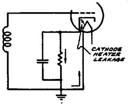
Fig. 2-22. Leakage between the cathode and heater produces a hum voltage
across the cathode resistor.
Distortion
Distortion is quite an extensive subject and in this process of signal tracing is checked in two ways: (1) by listening to a broadcast signal and (2) by visual observation or examination of the signal waveform. At the moment we are not concerned with which method is used.
You will remember we said that distortionless voltage amplification calls for a faithful reproduction in the plate circuit of the signal voltage applied to the grid. When this is accomplished, either the listening or visual test will enable detection of distortion.
Incorrect operating voltages are a very frequent cause of distortion and this applies to all types of voltage amplifiers. The determination of such contributing causes, as you can readily understand, is very simple. It is the measurement of the operating and control voltages at the tube elements during operation of the amplifier stage. By operation we mean with signal input.
It is not sufficient to check operating voltages only, because distortion may be due to the control voltage which is present only when the signal is applied to the receiver. Furthermore, these measured voltages should be the actual voltages, which means that they must be checked with such measuring equipment that will not load the circuits. In general the measuring equipment must have an input impedance sufficiently high so as to enable measurement of the actual voltages across the high resistances and tuned circuits present in the system.
Since the measurement of operating and control voltages is not difficult, we do not consider it necessary to enter upon a lengthy discussion. As to the normal voltages to be expected, service manuals containing the electrical specifications of the various receivers invariably state the correct operating voltages. It should be understood, of course, that these values may vary as much as plus or minus 20% from the value specified because of variations in resistors, tubes, and other component parts. In this connection, it might be well to add that service notes often specify the values of operating voltages as measured with comparatively low-resistance voltmeters, such as those of the 1000-ohms-per volt type. This means that the measured voltage is often much less than the actual operating voltage. However, more and more receiver manufacturers in the United States are making a change in their tabulations and are stating the actual voltage effective at the various tube elements. The voltage values so designated are those which would be indicated by an electronic or vacuum-tube voltmeter of very high input resistance. It is our belief that in time to come all voltage tabulations will specify the actual operating voltages rather than the lower values obtained when a lower-resistance voltmeter is used.
Leaving operating voltages for the present, distortion can be divided into a number of classifications. Hum has already been considered. What is left? In a general way we can list them as including (1) overloading, (2) rectification, (3) frequency distortion, (4) phase distortion, and (5) regeneration. Let us examine the significance of these various items. What do we mean by overloading? Basically it means that the signal voltage applied to the tube is greater than it is possible for the tube to handle.
This applies equally well to all types of amplifiers.
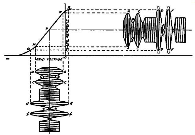
Fig. 23. The application of an excessively large input signal causes overloading
and distortion to take place in the output signal. This is shown by the flattened
peaks in the output signal at D and F.
Overloading. If we are speaking about overloading of the input circuit it means that the signal voltage fed into the tube is in excess of that permitted by the grid bias. You may recall the statements made earlier in this section that in amplifiers operated with grid-bias, one of the requirements for proper operation is that the grid remain negative at all times. If, however, the amplitude of the signal applied to the tube is such that it exceeds the grid bias and permits the grid to swing positive and attract electrons, then a direct current will flow between the grid and cathode and the signal in the plate circuit will be distorted. The distortion is caused by the fact that the grid-voltage change due to the signal follows the waveform of the signal only over that part of the cycle before the grid goes positive; consequently the plate-current waveform is a true amplified reproduction of the grid-voltage waveform only over that range of grid-voltage swing which is below the level where the grid swings positive. This is shown in diagrammatic form in Fig. 2-23.
The sloping line QMPNR is the grid voltage-plate current characteristic of the amplifier tube. The applied signal voltage is shown as the modulated wave abc-def. You will note that two amplitudes are shown for the modulated input signal: that represented by def is greater than that represented by abc. The operating point P on the grid voltage-plate current characteristic is assumed to be such as to accommodate the maximum amplitude of signal input. Between points M and N, the characteristic is linear. Beyond these two points the characteristic bends.
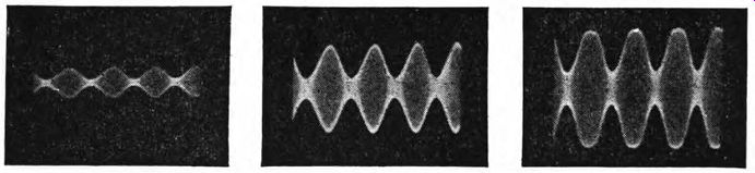
Figs. 2-24, 2-25, 2-26. The input and output signals are shown at the left.
When the input signal is further increased, the signal becomes distorted as
shown in the oscillogram at the extreme right.
Proper amplification of the weaker of the two input signal voltages is shown by the plate-current variation ABC corresponding to the grid-voltage variation abc. When the amplitude of the input signal voltage is increased to correspond with dd-1/, the input voltage now swings the grid voltage over the non-linear portion on both the positive and negative alternations. The positive alternations swing the grid positive because the peak amplitude of the signal exceeds the grid bias. The result is that the plate-current curve no longer remains a faithful amplified reproduction of the input signal voltage curve. Instead it flattens over that curved portion of the grid voltage-plate current characteristic which lies above N and also below M. The dotted portions of the plate-current curve at D and F indicate the shape of these peaks if there were no distortion. The same condition is shown in the three oscillograms of Figs. 2-24, 2-25 and 2-26. The first is the input modulated-carrier signal. The second is a correctly amplified signal and the third shows overloading. The flattened peaks can be clearly seen. The equivalent condition in an audio amplifier is shown in Figs. 2-27, 2-28 and 2-29.
Let us continue with the investigation of such a condition in a typical stage which is amplifying a modulated wave similar to the one we have been discussing. Suppose that we take as our basis, the amplifier shown in Fig. 2-30. We shall call the input signal e11 and the output signal e2 across the secondary of TS.
What happens during such a condition of overloading? Where in this circuit is the signal normal and where is it distorted?
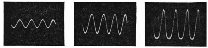
Figs. 2-27, 2-28, 2-29. The input and output audio signals are shown in the
two oscillograms at the left. When the input is further increased, overloading
takes place and the output signal becomes distorted as shown at the right.
For the usual conditions of overloading encountered in r-f and i-f amplifiers, the input signal across the tuned circuit will be found undistorted, which means that the signal at the control grid is undistorted. With further reference to the grid circuit, the ...
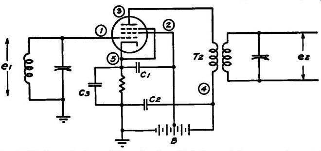
FIG. 2-30. A typical amplifier circuit which is used in connection with the
description of distortion in the text.
... comment that the signal is not distorted when the grid draws current should not be interpreted as being true in every single case. It is generally true in the case of r-f and i-f amplifiers, also in the case of some a-f amplifiers-but not in all a-f amplifiers.
In transformer-coupled a-f amplifiers, a great deal depends upon a number of factors, such as the output impedance of the winding which supplies the grid of the tube being overloaded, the amount of overloading, and the amount of impedance reflected from the grid winding back to the plate circuit of the preceding tube.
However, since we are interested solely in r-f amplifiers at the moment, we can repeat that the modulated signal at the grid will generally be undistorted despite the fact that the signal in the plate and screen circuits is distorted.
As is to be expected in accordance with what has been said concerning the effect of grid voltage variations upon the plate current, the presence of grid current affects all of the circuits which are associated with the electron stream. In other words, a check of the signal, if it exists in the screen circuit of a tetrode or pentode tube, will show the same general type of distortion as exists in the plate circuits. If for the moment we forget the presence of the by-pass condensers C1, C2, and C3 in Fig. 2-30, the signal at points 2, 3, 4 and 5 would be distorted. In other words, wherever the varying plate current causes the development of a signal voltage, the signal voltage will carry the distortion caused by the presence of grid current or overload of the grid circuit during certain portions of the input signal cycle. Naturally, the signal e_2 developed across the secondary of the trans former T2 will be distorted.
Continuing the discussion of this distorted signal, the time is opportune for the introduction of another subject associated with such distortion in amplifier circuits. This subject is the development of harmonic frequencies as a result of such nonlinear operation. Without attempting to discuss the subject at great length, one of the results of operation along the nonlinear portion of the grid voltage-plate current characteristic, the creation of a flattened plate-current wave, is the introduction within the tube of frequencies which are not present in the output--namely harmonic frequencies of the signal input. Thus if the input signal e1 is 1000 khz and the described condition of overloading exists, there will also be present across the terminals of T2, harmonic frequencies of 2000 khz; 3000 khz, etc. Of course the amplitude of these harmonic voltages is small in comparison with the fundamental frequency, especially since the plate circuit is tuned to 1000 khz, but they are present and this should be home in mind. Any signal-tracing device connected to T2 and resonated to the harmonic frequencies will show their presence under the conditions mentioned. However, this should not be accepted as a positive statement to the effect that these harmonic frequencies always will be detected; if the extent of overloading is not excessive, the amplitude of these harmonic frequencies may not be sufficient to be detectable.
What has been said as being true in r-f and i-f systems is also true in untuned circuits such as those in a-f amplifiers. In other words, the development of such harmonics is essentially a result of the overloading, and does not depend directly on the type of load circuit used or the frequency of the input signal. Where the plate circuit is untuned, as for example in a-f amplifiers, stronger voltages at the harmonic frequencies will be built up because the plate load circuit responds to the harmonics as well as to the fundamental. In contrast to this, the tuned load circuit used in r-f and i-f amplifiers tends to suppress the harmonic frequencies because of its low impedance at these frequencies.
You may recall a previous reference to the effect that when grid current flows a voltage drop is developed across whatever resistance exists in the grid· circuit. Accordingly a check for over loading is more easily effected in Fig. 2-31 than in Fig. 2-30 ...
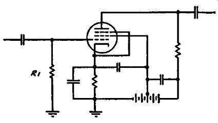
Fig. 2-31. When over loading in the grid circuit takes place, grid current
flows through R1 and develops a negative voltage at the grid.
... because of the presence of the high-resistance grid leak R1. A high-resistance d-c voltmeter, preferably a vacuum-tube volt meter, connected across this resistor between grid and ground, will show the d-c voltage developed as a result of the flow of grid current. This test is not done as easily in Fig. 2-30 because of the comparatively low d-c resistance of the tuned winding; this is true even if the transformer is an i-f unit. However, if the circuit is such that a high resistance, for example a filter resistor, is in the circuit as is R1 in Fig. 2-32, a test between points 1 and 2 will show the presence of grid current by the development of a d-c voltage across this resistor. If overloading is taking place point 2 will become negative with respect to point 1.
In all cases the grid current present when the grid circuit is overloaded develops a voltage across whatever resistances are connected in the grid circuit between the grid of the tube and the return point of the grid circuit to the cathode. This statement applies to all types of circuits, and is repeated to emphasize its importance.
Naturally the input signal does not have to exceed the negative grid bias before distortion will take place. It is only necessary ...
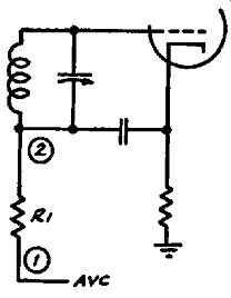
Fig. 2-32. The grid return circuit of a typical amplifier. When grid current
flows, point 2 becomes negative with respect to point 1.
... that the input signal be large enough so that the plate-current variation under the operating conditions is not linear-that is, is not proportional to the grid voltage variation. In cases of this type, the output signal will be distorted as a result of the excessively large swing. However, the input signal will in all instances be free from distortion since the signal is not sufficiently large to cause the flow of grid current.
Further consideration of the subject of amplifier overloading brings to the fore the fact that not only is the signal distorted, but in addition the output which can be obtained from a given stage is limited. In other words, increasing the signal input to an amplifier stage to the point beyond that at which overloading takes place does not produce a proportionately stronger signal than the amount of output obtained just before overloading be gins. That is, each and every amplifier operated at certain voltages is subject to definite signal-carrying capabilities. Consequently an amplifier stage can handle just so much signal and no more. Putting more in will not produce a greater signal in the output.
The type of distortion produced by overloading is often de scribed by the term amplitude distorted, because the amplitude of the output signal is not proportional to, or does not follow, the amplitude of the input signal.
With reference to the application of signal tracing to determine the point where the distortion originates, it stands to reason that it is between the point where the signal is normal and the point where it first appears distorted. To establish this point the serviceman's knowledge of circuit operation must be applied. As to the points where such distorted signal can be checked they are the various tube elements, such as the control grid, screen, plate, cathode, or the junctions of component parts connected to these points. Such test points have been identified in a general way in the preceding section and elaboration of technical details does not alter the test points. Although it is true that in the past it has not been possible to make measurements directly at such points as control grids and plates, modern-day signal tracing with proper equipment removes these limitations.
Rectification. Another cause of distortion in an amplifier is operation of the amplifier tube as a rectifier rather than as an amplifier. This comes about as the result of incorrect operating voltages, usually the control-grid bias, and is to be found in all types of amplifiers regardless of frequency range. Usually it appears when a strong signal is applied, and it is caused by an excessive value of grid bias; this biases the tube to such an extent that the negative half of the input signal voltage alternation is cut off, so that it does not appear in the plate circuit. Consequently the required linear relation between the input signal voltage and the output signal voltage is not maintained, and the output signal is distorted.
This problem of distortion due to cut-off was quite common~ place years ago before the development of special types of r-f and i-f amplifier tubes. The original run of r-f and i-f amplifier tubes were of the sharp cut-off variety, that is, the grid voltage plate current curve was very steep. Increasing the bias decreased the plate current very rapidly. This in turn decreased the amplification very rapidly. With the then commonplace methods of volume control in receivers-the use of negative bias-any attempt to attenuate a strong signal, such as that from a local station, resulted in the application of a high negative bias and in a change in the operating characteristic of the tube from an amplifier to a rectifier. The result was distortion. To correct this condition, the remote cut-off or variable-mu tube was developed, wherein the plate current and mutual conductance decreased gradually over a very high range of negative grid-bias values and operation as an amplifier was retained over the full range of bias values required to give volume control. Such tubes are used today in automatic-volume-control systems as well as in those simpler circuits wherein volume control is accomplished by the use of variable cathode bias resistors operated with or without associated antenna volume controls. An example of both types is given in Figs. 2-33 and 2-34.
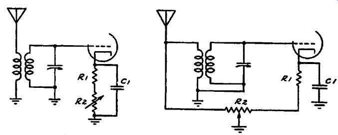
Figs. 2-33 left, 2-34 right. Two methods for controlling the transfer of the
signal. At the left, the gain of the stage is varied by varying the bias. At
the right, the coil is shunted in addition to the bias control.
It is important to note that the effects of rectification and over loading are similar in many respects. Although, as we have seen, rectification produces distortion of the negative peaks while overloading produces distortion of the positive peaks, the overall effect is essentially the same: in both cases, the signal in the output circuit is distorted and the defective condition must be corrected. Both rectification and overloading are examples of amplitude distortion to which we have previously referred.
Frequency Distortion. Another kind of distortion which may be found in all types of amplifier systems is known as frequency distortion. This term designates unequal amplification of the various frequencies which make up a signal voltage. For example, in an r-f system a complex modulated signal is made up of a number ·of components, essentially the carrier frequency and the side-band frequencies. If, for example, the modulating voltage is that developed by music produced by an orchestra, which might mean a frequency range of from 30 cycles to 7500 cycles, proper operation would call for uniform amplification of these sidebands extending over a range of 7500 cycles on either side of the carrier. However frequency distortion would tend to cut the amplitude of the upper limits of the sidebands. Similarly, in the case of an audio amplifier, frequency distortion is the unequal amplification of the various audio frequencies being passed through the amplifier system.
Now, it so happens that the vacuum tube is capable of nearly equal amplification over a wide range of frequencies so that frequency distortion, if present in a system, is usually due to some condition associated with the coupling device rather than with the amplifier tube itself. For this reason frequency distortion will be discussed in the section devoted to coupling units. This is especially desirable since frequency distortion in r-f, i-f and in some a-f systems is very closely associated with the performance of tuned circuits. No doubt you recall comments heard at different times about the need for flat-top adjustments of i-f trans formers, broad-band tuning, etc. All of these are for the purpose of minimizing or controlling the amount of frequency distortion.
One possible exception to the above is feedback. That is to say, feedback in an amplifier, and not necessarily associated with the coupling device, may be one reason why frequency distortion is present. This subject is discussed in detail in the paragraphs which follow.
Feedback in Amplifiers. Feedback plays an extremely important part in the operation of all types of amplifiers. In certain instances it is responsible for the introduction of distortion and then again in other cases it is responsible for the elimination of distortion. It all depends upon its undesired presence in one case and its deliberate introduction in the other. No doubt you are familiar with its use as a means of increasing the sensitivity of a receiver, in which case it is called regeneration.
Feedback in a communication system can best be described as the returning of a portion of the signal present in the output circuit of an amplifier to the input circuit of the same amplifier.
Although the amplifier may consist of a single tube or a complete system, since we are discussing single tubes, it might be best to first speak about feedback in a signal stage.
When such feedback exists and is of such character as to aid the input signal, it results in an amount of amplification from that stage which is in excess of that which would normally be calculated from the constants of the circuit; this action is called positive feedback or regeneration. On the other hand, if the feedback is of such character as to buck the input signal, then the amplification present in the system is less than that which would be determined by the constants of the circuit; this action is called negative feedback or degeneration.
Suppose that we start with feedback which is favorable to operation, that is, feedback which increases the signal. We recognize that maximum gain consistent with performance is always desirable in the average stage of amplification, but, if for some reason high gain causes instability, it is of little practical value and the amount of amplification must be reduced. As to the reason for lack of stability in an amplifier stage, it can readily be associated with certain definite conditions in the circuit. Just what these conditions are depends entirely upon the system, but in general it is due to stray coupling of one kind or another. In some cases this coupling may be through the grid-to-plate capacitance of the tubes used in the amplifier; in other instances it may be due to insufficient shielding of the input and output circuits.
The relative importance of these two contributing factors depends upon the type of tubes used and the type of amplifier.
For example, both tube capacities and shielding are of importance in amplifiers operating above audio frequencies, whereas the tube capacities are not usually of very great importance in audio amplifiers. As a matter of fact it is important to mention that inter-electrode tube capacities were of much greater importance in the past than they are at present. This is due to improvements in tube design and the development of the screen-grid tube, in which the grid-plate capacity, which was most troublesome in the triode, has been reduced to a point where it does not cause feed back between the grid and plate currents. However, since triodes are still in use in many receivers all over the world, it is desirable to consider them at this time.
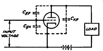
FIG. 2-35. A triode showing the capacities between the three elements of the
tube.
In order to comprehend the manner in which these tube capacities come into play, let us examine the typical triode in Fig. 2-35. Three capacities are shown: C,11., that between the control grid and the cathode; Grp, that between the control grid and the plate; and Gtp, that between the cathode and the plate. That such capacities exist within the tube is quite natural, since the various tube electrodes are metal surfaces located near each other. True, the surface areas are comparatively small, but small as they may be, they nevertheless form miniature condensers in which each electrode acts as one of the plates.
All of these capacities are important, but of the three the most important is G gp, the capacity between the control grid and the plate. In fact we can dismiss the control grid-to-cathode capacity by saying that in tuned circuits it becomes a part of the tuning capacity which shunts the grid circuit coil and in audio systems it simply shunts the input circuit connected across the control grid cathode circuit. This capacity has the effect of decreasing the amplification of the higher frequencies in audio and video amplifiers, but by no means is it as important as the control grid-plate capacity. The capacity between the cathode and plate likewise is of interest in connection with frequency distortion in audio and television amplifiers. However, let us investigate first the control grid-plate capacity.
This capacity provides a path whereby some of the signal present in the plate circuit can find its way back into the grid circuit, in other words feedback can occur from the output circuit of the tube to the input circuit of the tube. This feedback voltage is again amplified through the regular action of the tube and a portion of the signal voltage in the plate circuit of the tube is again fed back into the input circuit. If this feedback action is permitted to exist and reaches a sufficient magnitude, sustained oscillations are developed and the stage is no longer useful as an amplifier.
Two methods were widely used before the introduction of the screen-grid tube to overcome the effects of the signal voltage fed back from the plate to the grid circuits through the grid-plate capacity. One of these was the use of grid-suppressor resistors placed close to the control grid of the tube. These resistors absorbed sufficient energy as a result of signal voltage drop across them so that the amplification was reduced and oscillation pre vented. The second method, which was very widely used, was the method of neutralization which we shall now discuss. While these systems of neutralization are very old, there are still a large number of receivers which use neutralized triode stages of amplification in both r-f and i-f amplifier stages. It is therefore worth discussing these systems from the viewpoint of signal tracing.
The basic principle in the operation of a neutralized stage is the introduction of another signal voltage which cancels the voltage fed back through the grid-plate capacity. Two examples of such systems, both of which were used in numerous r-f amplifiers, are shown in Figs. 2-36 and 2-37. In Fig. 2-36, the signal voltage is secured from the plate circuit, through the winding L_n and this signal voltage is applied to the control grid through the neutralizing capacity C3. This neutralizing voltage is equal in magnitude and out-of-phase with that fed back from the plate circuit to the grid circuit through the grid-plate tube capacity Cgp, In this way the feedback is cancelled and maximum amplification is obtained without oscillation. A later modification of the first neutralizing system is shown in Fig. 2-37. In this circuit, the voltage is secured from the secondary of the tuned transformer which feeds the tube following the neutralized stage. The basis of neutralization is the same as previously stated.
A basic method of checking and adjusting neutralized receivers by means of signal tracing depends upon an indirect measurement of the neutralizing voltage. The first step in the neutralizing procedure is to insert a dummy tube in the stage being neutralized; a dummy tube is one which is of the same type as the tube used in the stage, but which has an open filament or heater. With this dummy tube in the socket, a signal should be fed to the antenna post of the receiver and the signal voltage measured at the control grid of the dummy tube. This value should be noted. Next the dummy tube should be removed and the regular tube inserted.
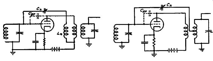
Figs. 2-36 (left) , 2-37 (right). These figures show neutralized r-f amplifier
stages and illustrate two different methods of obtaining the neutralizing voltage.
Again the signal voltage at the grid should be measured without making any changes in the tuning or in the setting of the signal generator. If the stage is perfectly neutralized, then the signal at the grid will have the same value as it had with the dummy tube in the socket. If the signal voltage at the grid is greater than that measured with the dummy tube in place, then this means that not enough signal is being fed back through the neutralizing winding to cancel the voltage reaching the grid through the grid plate capacity. Similarly, if the signal at the grid is less than that with the dummy tube, then too much neutralizing voltage is being fed back. In both cases, the neutralizing condenser should be adjusted so that the signal voltage at the grid remains un changed when the dummy tube is replaced by the regular tube; when this condition exists the neutralizing voltage exactly cancels the feedback voltage through the grid-plate capacity and the stage is therefore neutralized.
As stated earlier, neutralizing systems are still in use in old receivers but have not found much application in modern receivers because of the development of the tetrode and pentode tubes. The very low control grid-to-plate tube capacity of screen-grid tubes has eliminated the need for such balancing systems because the amount of signal voltage fed back from plate to grid within the tube is so low as not to cause such regenerative troubles. however, improper shielding or isolation of the various components which carry such high-frequency currents is still important and cannot be neglected. This is true with all types of tubes and includes not only possible electromagnetic coupling between components and connecting leads, but also electrostatic coupling between such items as sections of tuning condensers.
We may point out here that isolation of the various signal currents in the tube so that they are confined to their respective circuits is extremely important, as will be shown later in this section. The development of signal voltage across points which are common to more than one circuit will create a regenerative condition, with results which are similar to feedback between the plate and grid circuits, although the exact contributing causes are not the same as those outlined.
Regeneration of such extent as to cause sustained oscillations in a tuned stage of any kind impairs the operation of that stage as an amplifier of the original signal. When such a condition exists, amplification is still being obtained, for without it there would be no state of oscillation, but proper signal transfer between stages is not being accomplished. Of course, it is not essential that a signal be fed into the amplifier in order that it develop sustained oscillations. If sufficient feedback takes place between the output and input circuits, sustained oscillations will be developed in the stage.
The presence of oscillations can be checked by means of signal tracing by considering the oscillating tube as a generator of a signal without any external signal input to the stage. The problem of locating an oscillating stage in a multi-stage amplifying system is somewhat more difficult, and is described later in this volume.
Regeneration can be due to conditions other than feedback through the tube capacities or induction between components and their connections. It can be created as the result of an impedance which is common to more than one circuit. To present this subject properly it is first necessary to speak about multi-stage voltage amplifiers.
Multi-Stage Voltage Amplifiers
What is meant by a multi-stage voltage amplifier? As the name implies, it is an arrangement whereby the amplified signal from one stage is fed to the next stage and so on until the signal level is sufficient to meet the requirements for rectification or for conversion from voltage to power as in the case of the audio system. Thus any type of amplifier which contains more than one stage, whether r-f, i-f or a-f, is a multi-stage amplifier.
Typical examples of such multi-stage amplifiers are to be found in commercial receivers of all types. In all such systems the total amplification available with the system is equal to the product of the respective amplification values of each stage. Thus if a two stage r-f amplifier is being considered, and the first stage provides an amplification of 10 and the second stage provides an amplification of 15, then the overall amplification in the system is 10 x 15 or 150. These figures are purely illustrative and not to be accepted as an indication of the gain of any one particular radio-frequency amplifier. If, for example, a two stage i-f amplifier has individual stage gains of 50 and 70, the total gain is 50 x 70, or 3500. As far as operation of a multi-stage amplifier is concerned, it is no different from that of the individual stages. All that has been said about the individual stages separately is true of the individual stages of a complete amplifier system. The relation between the tube and the load impedances, the factors determining distortion, the function of the respective components, the distribution of the signal in the separate stages-all these are similar to conditions in a single amplifier stage.
There are of course a number of differences between the performance of a single stage and a multi-stage amplifier. One of these is regeneration, which will be discussed later. It is extremely difficult to minimize regeneration in a complete system to a value as low as that which prevails in a single stage used by itself.
Invariably some signal feedback is present in a complete system and this tends either to increase or decrease the overall amplification, so that the total amplification is more or less than the product of the individual stage gains. It all depends upon the direction of the feedback, that is, whether it aids or bucks, whether it is regenerative or degenerative.
To point out the similarity between single stage and multi stage amplifiers, we show in Fig. 2-38 a typical two stage tuned r-f amplifier. Note that the individual stages are identical with those which we have previously considered and that a common power supply is used for each of the separate stages. The input voltage to the amplifier is e1 at the control grid of the first tube, and the final output signal voltage is e2 which is present across the tuned winding which feeds the diode rectifier.
Fig. 2-38. A typical two stage tuned r-f amplifier. The overall amplification
of the signal is obtained by multiplying the gain of the two stages.
The overall gain in this system is that which is obtained between the control grid of the first tube and the diode plate of tube V3. The gain of the first stage is that between the control grid of tube V1 and the control grid of tube V2. Similarly the gain in the second stage is that between the control grid of tube V2 and the diode plate of tube V3. In the event that some other tube were used in place of the diode, the gain of the last stage would be measured by taking the signal level across the output winding.
You should of course realize that there is nothing rigid in these statements concerning the manner in which the amplification or gain of the system is calculated. In general, the gain can be measured between any two points and the measurements continued in this way until the output of the amplifier is reached.
Thus in the circuit of Fig. 2-38 the gain can first be measured between the grid and the plate of the tube V 1, and then this measurement can be followed by a measurement of the gain between the primary and secondary windings of the transformer.
As you can readily see, the first measurement gives a measure of the performance of the tube, while the second measurement describes the functioning of the transformer.
Previously we pointed out that one essential difference between multi-stage amplifiers and single-stage amplifiers is the possibility of interaction between the several stages with a resultant increase or decrease in the overall gain. As we shall see in the following sections, a number of different methods are used to minimize this interaction. Since amplifiers almost invariably use the same common power supply, interaction through the power supply is a common cause of feedback. To eliminate this feed back through the power supply, it is general practice to decouple or isolate the power supply leads which feed the d-c voltages to the electrodes of each of the individual stages. Generally, these decoupling units take the form of by-pass condensers and filter resistors which prevent a signal voltage from being built up across the power supply.
It is unnecessary at this point to discuss at length the manner in which signal tracing is carried out in multi-stage amplifiers.
This is covered in detail in the other sections of this book which deal with the various types of receiver circuits.
Signal Tracing in Power Amplifiers
With certain modifications, which will be covered in this section, signal tracing in power-amplifier circuits follows along the same lines as in voltage amplifiers. In general the circuit impedances are lower and the signal levels higher. Both of these effects tend to simplify signal tracing because there is less possibility of reacting on the circuit and because the higher signal levels simplify picking up the signal.
A typical power amplifier stage is shown in Fig. 2-39. Insofar as the circuit connections are concerned, the stage is similar to a voltage amplifier stage. However, the operating conditions and circuit constants of power amplifiers differ from those of voltage amplifiers because the function of the voltage amplifier is to de liver the maximum voltage across the load, while the function of the power amplifier is to deliver the maximum power to the load. Unlike the conditions met in voltage amplifiers, a large value of load resistance does not provide the maximum amount of power and is therefore undesirable for use with power amplifiers. Actually it turns out that the maximum amount of power is delivered to the load when the resistance of the load is equal to the plate resistance of the tube. This is but another application of the broad principle that a generator of any type will deliver the maximum amount of power when the load impedance is "matched" to the internal impedance of the generator. However, as we shall see later in this section, this principle of matching the load and plate impedances is often modified so as to decrease the distortion.
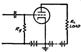
FIG. 2-39. A basic power amplifier circuit.
The power is developed across the load RL.
In a typical triode output stage using a type 45 tube, the load resistance recommended is equal to 4600 ohms, although the plate resistance of the tube under the operating conditions is equal to only 1700 ohms. This illustrates the point that in practice the load resistance is often made somewhat greater than the plate resistance of the tube in order to minimize distortion. Of course, the use of this higher load resistance does lower the efficiency of the amplifier somewhat, but because of the straightening effect which it has on the tube characteristic, it makes possible a higher power output with less distortion.
The average gain from the grid to the plate of power amplifiers is of interest because it provides an index as to the operation of the stage. For a single stage using a type 45 tube, the average gain from grid to plate is about 2.7. In other words, with a 10 volt signal at the grid of the tube, the signal at the plate should be equal to about 27 volts. This amplification may seem quite small, but it should be kept in mind that the tube is functioning as a power amplifier and not as a voltage amplifier.
In the operation of pentodes as power amplifiers, the difference in choice of load resistance is again evident. In a typical pentode output stage using a type 6F6 or 2A5, the recommended value of load resistance is 7000 ohms whereas the plate resistance of the tube is about 80,000 ohms. As in the case of triodes, the load resistance is not made equal to the plate resistance because of distortion considerations. It is found that the distortion can be decreased by using a value of load resistance which is about one tenth that of the plate resistance. Although this low value of load resistance reduces the voltage amplification, the power output is maintained at a high value. For a typical pentode output stage using a 6F6, the amplification from the grid to plate is about 16. In other words, a 5-volt signal at the grid will produce an 80-volt signal at the plate of the tube. Note that the voltage amplification for pentodes is appreciably higher than that for triodes.
Coupling to Speaker
In practice the impedance of the average speaker voice coil differs widely from the values of load resistance recommended for power output tubes. Thus the average speaker voice coil resistance is several ohms, whereas in order to transfer power efficiently from a power amplifier stage, a load resistance measured in thousands of ohms is required. Some method is required ...
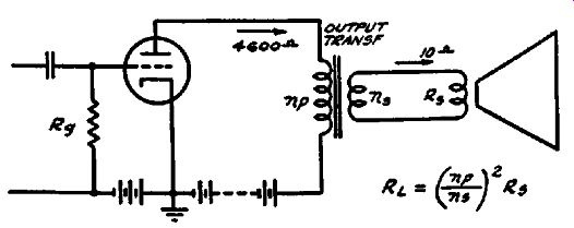
Fig. 2-40. Because the load impedance of the average power tube is much higher
than the impedance of speaker voice coils, an output transformer is required
to match the two impedances.
... to match the impedance of the voice coil, and the method which is universally used employs a speaker matching transformer.
Essentially this output transformer, as it is generally called, changes the impedance of the voice coil so as to make it appear to the plate of the tube as a much higher impedance than the actual value of the voice coil impedance. A typical output circuit is shown in Fig. 2-40. The turn ratio of the transformer is the important factor which determines the manner in which the voice coil impedance is changed. If, for example, the ratio of the primary to the secondary turns is equal to 30, then a 10-ohm voice coil would appear to the plate of the output tube as a resistance of 10 x (30) 2 or 9000 ohms. In general, the load which the output tube sees as it looks into the primary winding of the output transformer is equal to the actual resistance of the voice coil multiplied by the square of the turn ratio. Mathematically, the load resistance which the transformer presents is thus equal to Rs X ( np/ns ) ^ 2.
Other factors besides the turn ratio affect the operation of the transformer as an impedance changing device, but these are primarily design considerations and therefore will not be considered here.
Signal Levels
We are now in a position to examine the various signal levels which normally exist in a power amplifier stage. In the case of triode output tubes, the gain which can be expected is about 2/3 that of the amplification factor of the tube. This is so because the load resistance generally used is approximately twice the plate resistance of the tube. For the type 45 tube, the amplification factor is 3.5 and the gain from grid to plate is about 2.7; for the type 2A3, the amplification factor is 4.2 and the gain from grid to plate is about 3.2, similarly; for the type 6F6G used as a triode with the screen grid and plate tied together, the amplification factor is 6.8 and the gain from grid to plate is about 4.1. Although the rule for triodes that the gain from grid to plate is about 2/3 the amplification factor is not always accurately true, it holds approximately and is always close enough so that it provides information on how much step-up in signal can be expected from grid to plate.
In the case of tetrode and pentode tubes, as has previously been mentioned, the voltage gain from grid to plate is higher than for triodes. The actual values vary from about 10 to 20 depending upon the tube type, and a good average value when in doubt is that the gain should be about 15. For a type 6F6 pentode, the gain is 17; for a type 6K6G pentode, the gain is 15; for a type 6L6 beam power tetrode, the gain is about 13. In all of these cases, the actual gain from grid to plate is considerably less than the amplification factors which are of the order of 200. For a stage using a type 6F6 pentode, working into a 10-ohm voice coil, the step-down from plate to voice coil is about 26.
Thus with a 10-volt signal at the grid of a 6F6, the signal at the plate is about 160 volts, and the signal at the voice coil is about 6 volts. It is interesting to note that because of the higher load resistance required for pentode type tubes, the step-down between the plate and voice coil is greater for pentodes than it is for triodes. The greater power sensitivity of the pentode type is apparent since it produces about 5 times the voltage, or 25 times the power, across the same voice-coil resistance for the same value of input signal.
The voltage step-down from the plate of the output tube to the voice coil depends upon (1) the rated load resistance of the output tube and (2) the voice-coil resistance. We shall first give some typical values and then show how the expected step-down can always be computed from a knowledge of the load resistance of the output tube and the voice-coil resistance. For a type 45 triode with a 4600-ohm load, the step-down from plate to a 10 ohm voice coil is about 21. Thus with a 10-volt signal at the grid of a type 45 output tube, the signal at the plate should be about 27 volts and the signal at the voice coil should be about 1.3 volts.
In the general case, the step-down which is normal between the plate and the voice coil can be computed from the value of the load resistance and the voice-coil resistance. If the load resistance is equal to RL and the voice-coil resistance is equal to R., then the voltage step-down from plate to voice coil is equal to the square root of the ratio between the load resistance and the voice coil resistance. In symbols, the voltage step down= y RL/R. The step-down ratio expressed by this formula is of course also equal to the turn ratio of the output transformer. It will be noted that the greater the load resistance and the smaller the voice-coil resistance, the greater will be the step-down in the signal voltage between the plate and the voice coil.
Push-Pull Operation
To obtain greater power output than is possible with a single tube, two similar tubes are very often used in push-pull. This type of output circuit is shown in Fig. 2-41 for the case where a self-bias resistor is used to supply the necessary grid bias. In operation, a signal is applied to the grid of V1 and at the same time an equal signal is applied to the grid of V2. Although equal signals are applied to both grids in order to obtain push-pull action, the signals applied to G1 and G2 must be opposite in phase.
Thus, at the instant when the grid of Vt is least negative on the ...
Fig. 2-41. A basic push-pull amplifier circuit. Because of the balanced circuit,
no signal voltages are present at either K or M.
... positive peak of the cycle, the grid of V2 will be more negative by a like amount on the negative peak of the cycle. As a result, the current through the primary winding of the power transformer receives two contributions which add to each other: one of these is the increase in the plate current of VJ due to the positive grid voltage, and the other is the decrease in plate current of V2 due to the negative grid voltage.
On the second half of the cycle, G 1 becomes more negative and G2 less positive by an equal amount. For this half cycle, the plate current of VJ decreases, and the plate current of V2 increases by approximately the same amount. Again these two changes in plate current are combined in the primary winding and produce a resultant change in flux which is equal approximately to twice that produced by either one of the two tubes.
The advantage of the push-pull circuit results from the fact that each half cycle of the voltage induced in the secondary winding of the transformer receives a contribution from both tubes- a contribution from the negative part of the characteristic of one tube and a contribution from the positive part of the characteristic of the other tube. In other words, each half cycle is made up of a "push" from one tube and a "pull" from the other tube.
An important consequence of this is that if, for example, the positive and negative halves of the input signal are similar, then the positive and negative halves of the output signal must also be similar. In other words, whatever distortion may be introduced by a push-pull amplifier stage will affect both halves of the cycle to the same extent. Although the output waveform may not necessarily be exactly the same as the input waveform, it will always be true in a push-pull amplifier that the output wave form will have identical positive and negative half cycles. This is merely another way of saying that the output wave of a push pull amplifier possesses mirror symmetry and therefore a push pull amplifier cannot introduce even harmonic distortion into the output of the amplifier.
The elimination of even harmonic distortion makes it possible for a push-pull amplifier to deliver more than twice the output which it is possible to obtain from a single tube of the same type.
Where a single tube is used, the curvature of the grid voltage plate current characteristic introduces even harmonic distortion which limits the useful output of the stage. In the push-pull circuit, however, the signal is divided between the two tubes and even harmonic distortion which arises from the curvature of the characteristic cancels out. Thus it is possible to use a greater grid swing and to obtain a correspondingly greater power output without excessive distortion.
The signal distribution at the various points in a push-pull amplifier is of interest. At the grids, we have seen that the signal voltages are equal but opposite in phase. At the two plates, the amplified signals appear, and again they are equal in value and 180 degrees out of phase just as at the grids. The output trans former, as we have seen, combines the contributions from the two tubes and produces the final signal voltage across the voice coil of the speaker.
It is important to note that during operation of a push-pull stage there is no signal voltage at the cathode return point K or at the plate return point M, in Fig. 2-41. This can be seen from the fact that the total plate current drawn from the power supply is constant throughout every point in the cycle. Thus when the plate current of the one tube increases from its no-signal value, the plate current of the other tube decreases by the same amount; as a result the total current drain of the two tubes remains the same and is always equal to the sum of the no-signal plate Currents of the two tubes.
An important consequence of the fact that the combined plate currents of two tubes in push-pull remain constant is the fact that no filtering is required at the cathode or at the center-tap of the output transformer. In some receivers a by-pass condenser is used across the cathode resistor but the primary function of this condenser is to remove any signal voltages which may be developed because of differences in the characteristics of the two tubes. The filtering in the B-supply voltage for a push-pull output stage does not have to be as perfect as for a single-ended output stage. This can be seen from the fact that any hum voltage which may be present at point M will cause hum currents to flow through the primary winding of the output transformer, but these hum currents will cancel each other so that no hum voltage will be induced in the secondary winding .. This makes it possible to feed push-pull output tubes directly from the input to the filter and in some receivers it will be found that as much as 30 volts of 120-cycle hum voltage may exist at point M without introducing any noticeable hum into the output.
In circuits where the center-tap of the output transformer is connected directly to the filter input, care must be exercised in measuring the signal voltages at P1 and P2 because of the high value of hum voltage which is present at these points. If a small value of signal input is used for testing, this large hum voltage may obscure the signal voltage measurements, and in any event will cause an error in the measurement of the signal voltage. In cases of this kind, errors due to the presence of the hum voltage can be eliminated from the signal-voltage measurement by measuring the signal voltage present across P1-M and across Pt-M'. This means that the low side of the instrument being used for the measurement must be connected to M. Care should be taken to avoid coming in contact with the instrument ground while this measurement is made since the instrument ground is some 250 volts above ground. When the measurement is completed, the instrument ground should be returned to its normal position.
In push-pull circuits, the step-up in the signal from the grid to the plate is approximately the same as for a single-ended amplifier. However, because the voice coil receives contributions from two tubes, the power delivered to the voice coil is approximately twice as great as for a single-ended amplifier. As a result, the signal voltage produced across the voice coil is equal to approximately 1.4 times the value which holds for a single-ended amplifier. There is thus a smaller step-down of voltage between the plate of either one of the push-pull output tubes than is the case for a single-ended amplifier.
Classes of Amplifiers
In discussing power amplifiers, it is customary to divide them into different classes depending upon the fraction of the signal cycle during which plate current flows under rated conditions.
In the Class A amplifier, which has been taken up under voltage amplifiers, it was shown that the grid bias and other operating conditions are so adjusted that plate current flows throughout the complete cycle. When producing its full rated output, the peak value of the signal is always less than the grid bias so that a stage operating Class A never draws grid current. Other characteristics of a Class A stage are the low percentage of distortion, and the high power amplification resulting from the fact that practically no power is required in the input circuit.
When greater power is required from two tubes than can be obtained from Class A operation, the tubes are used in push-pull in Class AB. A distinguishing feature of Class AB operation is that a higher value of grid bias is used, so that the plate current is reduced to a value lower than for Class A operation. The use of a higher value of bias makes it possible to raise the supply voltages without exceeding the allowable dissipation of the tube, and these higher supply voltages in turn make possible higher output.
For small values of input signal, a Class AB amplifier operates as a Class A amplifier since plate current flows throughout the cycle and since operation is essentially over the linear portion of the tube characteristic. For higher values of input signal and power output, the operation is no longer Class A since plate Current cut-off is reached on the negative half of the cycle. Depending upon whether or not the tubes draw grid current on the positive halves of the cycle, the operation of the stage is said to be Class AB1 or Class AB2. The subscript 1 indicates that no grid current is drawn, while the subscript 2 indicates that grid current is drawn during the positive peaks of the cycle.
Class B Amplifier
When the maximum power output is desired from tubes of a given size, Class B operation is generally used. In a Class B stage, two tubes are used in push-pull and the bias and operating conditions are such that plate current flows in each tube only on one half of the cycle. In other words, with no signal input, the bias is adjusted so that the plate current is approximately zero.
Clearly, Class B operation is an extension of Class AB in that the bias is made more negative so that the plate current is essentially zero when no signal is applied. Actually, special tubes have been developed for Class B operation. These tubes have a high amplification factor as a result of which the plate current corresponding to zero bias is very small. This makes it possible to operate these tubes with the cathodes grounded and with the grids returned directly to ground.
The method of operation of a Class B amplifier resembles that of a Class A amplifier with this important exception: the contribution which the voice coil signal receives from each half cycle of the input signal is made up only of a push from that tube which has a positive signal voltage on its grid. The other tube, unlike in Class A and Class AB operation, has a negative part of the signal on its grid and is therefore driven beyond cut-off.
Because the output signal receives only a ''push" from one tube and no simultaneous "pull" from the other tube, the Class B amplifier is sometimes called a "Push-Push" amplifier. However, the circuit connections are of course identical with those of a push-pull Class A amplifier.
Because the current drain on the power supply varies with the input signal, power supplies which are designed for Class AB and Class B amplifiers have better regulation than those for Class A amplifiers. The variation in output voltage of the power supply is usually kept to a low value by using power transformers and chokes having low d-c resistance, and by using rectifier tubes which have a low internal voltage drop. In some receivers mercury vapor rectifier tubes have been used because of their low and constant internal voltage drop. A choke-input filter is often used to improve the regulation. Although a choke-input filter produces a lower output voltage for a given input from the rectifier, it is often used because of the improved regulation which it makes possible.
Unlike the Class A amplifier, the grids of amplifier tubes used in a Class B circuit are driven positive so that current flows in the grid circuit. This in turn means that a certain amount of power is consumed in the grid circuit and this power must be supplied by the preceding stage. To supply this grid-circuit power, the preceding tube is arranged as a power amplifier and is transformer-coupled to match the grid-circuit impedance of the Class B output tubes. This tube is generally called the driver tube, because of the fact that it 11 drives" the Class B tubes by supplying the necessary grid voltage and grid current.
FIG. 2-42. A typical Class B amplifier. The numbers within the small circles
represent the signal voltages at the various points in the driver and output
stages.
The transformer used to couple the driver stage to the Class B output tubes is generally a step-down transformer in order to match the comparatively high plate resistance of the driver, which is operated Class A, to the comparatively low input resistance of the Class B tubes. The voltage ratio of this trans former-the ratio between the signal voltage across the primary to that across half the secondary-may vary from about 2: 1 to about 5: 1. There are numerous other considerations which enter into the design of the driver transformer, but these are design considerations and are beyond the scope of this book.
The signal voltage levels which can be expected in Class B amplifiers are shown with the aid of Fig. 2-42 which represents a typical Class B amplifier design using type 6N7 tubes. The driver stage employs the two sections of the 6N7 in parallel as a Class A amplifier and provides a voltage gain of 25. Assuming a 2-volt input signal to the grid of the driver, this brings the signal level at the driver plate up to 50 volts. The step-down transformer which couples the driver to the Class B output stage has a step-down ratio of primary to one-half secondary equal to 5: 1. As a result, the signal voltage of the Class B grids is equal to one-fifth the signal at the plate, or 10 volts. The voltage amplification from grid to plate is about ten and this brings the signal level at each of the plates up to 100 volts. Assuming that the voice coil resistance is 5 ohms, the signal voltage developed across the voice coil is equal to about 4 volts. The latter can be computed by referring to the recommended plate-to-plate resistance of the Class B stage shown in the tube handbooks, and using the formula previously given.