AMAZON multi-meters discounts AMAZON oscilloscope discounts
THROUGHOUT this book we have assumed that the instrument required for making the necessary signal-tracing measurements was available. We were justified in doing this because in the other sections of the book we were concerned primarily with signal tracing as a method1 and not with the means or instrument required for tracing the signal. But it goes almost without saying that any system of testing is only as good as the instruments which are employed and so a proper comprehension of signal tracing requires that you understand the instruments used in signal tracing.
In this section we shall from time to time illustrate the points being discussed by references to the Rider Chanalyst. This is not to say that the Rider Chanalyst is the only signal-tracing instrument but rather it is a natural consequence of the fact that the Chanalyst was the pioneer signal-tracing instrument to which other commercial instruments owe their existence. It was not until the Rider Chanalyst had demonstrated conclusively the advantages of signal tracing that other instruments made their appearance. Of course these instruments are not identical with the Chanalyst and it is not our purpose here to show all the variations possible in signal-tracing instruments. For just as there are many receivers ranging all the way from cheap midgets to high-fidelity receivers, so many signal-tracing instruments are possible. With all these variations we are not concerned, but we do want to discuss the fundamental requirements of signal tracing instruments. And if in so doing we illustrate our points by references to a time-proved signal-tracing instrument, we feel that there is ample justification.
Checking RF-IF Signals
In applying signal-tracing methods we have seen that it must be possible to check the signal at every point in the receiver, starting at the antenna and following right through to the voice coil. Since the natural starting point of the signal is in the r-f section of the receiver, it is logical for you to ask about the instrument used for tracing the signal in this part of the receiver.
What type of instrument is required for this purpose? Essentially of course the radio-frequency part of our signal tracing instrument, which for convenience we shall call the rf-if channel, must be a vacuum-tube voltmeter of some kind. For it must have enough sensitivity to enable picking up the signal right through from the antenna coil, where the signal level is measured in microvolts. But it cannot be a vacuum-tube volt meter of conventional design because such voltmeters do not have sufficient sensitivity, and in addition place too great a load upon the circuit being checked. Both of these difficulties are eliminated by using a tuned amplifier type of vacuum-tube volt meter with a special test probe. The rf-if channel in the Rider Chanalyst employs such an arrangement and its advantages will be clear from the description in the following paragraphs.
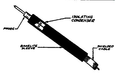
Fig. 12-1. The special test probe shown at the right makes it possible to
measure r-f voltages without detuning the circuit. The cable and input capacity
are isolated by means of the air-gap condenser near the probe tip.
Let us start with the input circuit to the channel used for checking r-f signals. Of the greatest importance is the probe which connects the instrument to the receiver under test. As Fig. 12-1 shows, this probe is of special design and construction so as to minimize reaction on the receiver under test. Referring to the illustration, you will observe that the probe point is not connected directly to the shielded conductor but instead a small air gap isolates the probe point from the conductor. Effectively this means that the probe point is joined to the instrument through a small condenser the value of which is regulated by the size of the air gap. In the Rider Chanalyst this air gap forms a condenser of about 1.5 u-u-f capacity. Now since this air gap is close to the point at which the probe is touched to the receiver under test, it means that the capacity shunted across the test point is less than 2 u-u-f.
In a real sense the entire procedure of signal tracing depends upon the probe arrangement which we have just described. By means of this special probe, we can connect directly across tuned circuits, to the controlled grid and plate of tubes,-in fact to any point where there is an r-f or i-f signal-and measure the signal voltage without any appreciable detuning or loading of the circuit. At the same time it is possible for us to use a shielded flexible cable of convenient dimensions to connect the probe to the input of the instrument. Of course the air gap prevents this cable capacity and the input capacity of the instrument from appearing across the test point.
As we mentioned earlier, a tuned amplifier must be used to obtain the sensitivity required in r-f signal tracing, as well as to supply the selectivity necessary to distinguish among signals of different frequency which are often present at the same point.
The input circuit of such an amplifier is shown in Fig. 12-2. The shielded cable is plugged into a jack on the instrument panel which connects through C5 to the grid of the first amplifier tube.
By means of the switch S1 it is possible to select any one of four values of capacity which shunt the grid to ground.
What is the purpose of these four condensers? As we shall see in a moment, each of these condensers forms a capacity divider in conjunction with the small isolating condenser formed by the air gap in the probe. Thus when the switch is in the X1 position, one-hundredth of the signal present at the probe point is applied to the input grid. This of course is because the capacity of C1 is one hundred times as great as the probe capacity of 1.5 uuf. C1 is shown dotted because it is not made up of an actual condenser but consists of the capacity of the shielded cable, the switch, the tube, and the wiring. In the X10 position, a similar action takes place. Here the capacity of C2 is made 1,000 times as great as the probe capacity so that only one-thousandth of the signal reaches the input grid. Similarly, C3 and C4 are made progressively larger to provide additional attenuation so that in all the switch S1 supplies multiplier values of 1, 10, 100, and 1000. Thus it provides us with a simple means for determining the relative strength of signals. We might point out that shielding is no problem with this simple but effective type of multiplier because only as much signal as is selected by means of S1 enters the instrument through the shielded cable. The rest of the signal voltage drop takes place across the air-gap condenser in the probe sleeve.
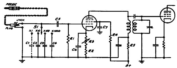
Fig. 12-2. The input circuit of an amplifier suitable for signal tracing measurements.
The multiplier switch S1 and the control R3 make it possible to compare signal
levels at different points in the receiver under test.
We have just seen that S1 provides us with a means for determining the relative strength of signals in steps of ten. To obtain a continuous attenuation over a range of ten to one, the circuit in Fig. 12-2 is provided with a cathode rheostat RS which varies the gain of the stage over a ten-to-one range. In conjunction with S1, R3 enables us to obtain continuous attenuation over a range of 10,000. This has been found to be sufficient to handle the problems which occur in the course of signal tracing.
Satisfactory accuracy in the multiplier is secured by using accurate condensers for the capacity divider. As far as the ten to-one signal level control is concerned, the use of self-bias and series operation of the screen makes the calibration of this control largely independent of variations in tube characteristics.
We need not discuss in detail the three-stage tuned r-f amplifier used following the input circuit. In many respects it is similar to a modern tuned r-f receiver with the exception that special attention is given to securing a flat response over the complete tuning range. In the Rider Chanalyst, special transformers with the primaries resonated below the low-frequency end of the band are used in order to obtain a flat response. To secure stability the components are well shielded and individual filtering is used in the screen and plate-supply leads, as well as individual self bias resistors. The overall gain is approximately 100,000. Although the tuned r-f amplifier is more expensive than the super heterodyne type, it has the advantage that for each signal which is present at the test point, only one response is obtained on the signal-tracing instrument. In connection with the frequency range of the amplifier, this important point should be noted: a wide frequency range is not usually required because once the receiver is made to operate properly on the broadcast band and the oscillator has been checked on the inoperative short-wave band, the trouble is already localized. This is explained in detail in Section 9.
The detector circuit used following the amplifier is a diode rectifier. The output of this circuit is arranged so that it controls a 6E5 electron-ray indicator tube which is used to supply a reference output level corresponding to the signal required to close the shadow completely. At the same time provision is made in the output for connecting headphones so as to listen to the signal, or an oscillograph so as to be able to view the waveform. For practically all purposes, as we have previously seen, the check of output level provided by the 6E5, or the check of quality made by listening to the signal, is sufficient.
An elaborate meter type of output indicator is not required because we are interested primarily in the relative values of the signal in various parts of the receiver. The multiplier and level controls previously described gives us these relative values of signal strengths and thus it is only necessary for the output indicator in the signal-tracing instrument to provide a reference value.
A convenient arrangement for this purpose is to use a 6E5 tube and to let the reference indication be the signal output required to close the shadow completely. It is possible to provide a jack across the diode load so that a meter can be inserted in special cases where the actual value of output signal is desired. This occurs but seldom in the course of practical servicing work.
The quality of the signal, whether noise is present, etc., can conveniently be determined by using a pair of crystal phones across the diode load to listen to the signal. Where a visual check is desired, the waveform can be examined by plugging an oscillograph into the jack to connect its input across the diode load.
In this way the r-f amplifier in the signal-tracing instrument supplements the oscillograph by providing the necessary r-f gain.
Since the oscillograph amplifiers do not function at radio frequencies, the sensitivity of the oscillograph is of course not great enough to permit connecting it directly to the receiver. In fact even where the oscillograph has a wide-band amplifier, the input capacitance is ordinarily of the order of 30 uuf or more so that it cannot be connected directly across a tuned circuit.
A-F Signal Tracing
Signal tracing in a-f circuits is very much simpler than signal tracing in r-f circuits and so also are the instruments which are required. One of the earliest instruments for signal tracing in a-f circuits was a set of headphones. All of you have used this crude form of a-f signal tracing at one time or another and are therefore familiar with its limitations. In the first place, high impedance circuits are often encountered which are loaded excessively by the phones so that it is difficult to determine just what is taking place in the circuit. A second disadvantage of the head phones is that it is difficult to determine approximately how much step-up in signal is obtained as the signal is traced through successive stages.
Both these disadvantages can be removed by using a single stage of a-f amplification. Because of the high input resistance of the vacuum tube, the loading of the circuit being checked is minimized. It is of course desirable to use a shielded cable and probe, but no special isolating arrangement need be used because the input capacity is not important at audio frequencies. As far as the check of relative signal strengths is concerned, a calibrated potentiometer can be used in the input or cathode circuit of the a-f stage. This in conjunction with a simple multiplier switch can easily be arranged to check signals ranging from less than 0.1 volt to 200 volts.
In the output circuit of the single-stage amplifier, a diode rectifier circuit feeding a 6E5 can be arranged to serve as a reference indicator. This is similar to the arrangement used in the case of the rf-if channel so that no further discussion is required. Provision for listening to the signal is desirable and a jack across the output should be provided for this purpose. Unlike r-f measurements, a-f signal tracing can be conducted directly with the oscillograph since the internal amplifiers provide sufficient sensitivity for checking the signal even in the low-level stages. however for rapid work, and for tracing noise, it is very convenient to use the headphones in the output jack of the a-f stage.
Checking the Oscillator
In another part of this book we described the manner in which checking the oscillator circuit is related to signal tracing and the localization of trouble in receivers. As we explained there, the r-f voltage generated by the receiver oscillator is no different from any other signal voltage and as such it can be checked in exactly the same manner as other signal voltages. Actually, the problem of checking the oscillator signal is considerably simpler because the voltage available is so much larger than that which we find in the remaining parts of the r-f section of the receiver.
Thus the oscillator voltage is almost invariably at least several volts, whereas the other r-f signal voltages are measured in milli volts.
Where the frequency of the oscillator is within the range of the rf-if channel, this section of the signal-tracing instrument can be used to check the oscillator voltage. To avoid reaction or loading of the oscillator circuit, the special test probe containing an isolating condenser is used; this is the same probe illustrated in Fig. 12-1, which we described in connection with r-f signal checking.
As is pointed out elsewhere in this book, the reaction on the circuit can be reduced to considerably less than 1 µ.µ.f by holding the probe close to, but not in contact with, the high side of the oscillator section of the tuning condenser; any other appropriate point in the oscillator circuit instead of the condenser can of course be selected.
It is often convenient to use a separate channel for checking the operation of the oscillator. The chief justification for a separate channel for this purpose is its utility in the servicing of intermittent receivers and the simplicity of the circuit. Because of the high signal voltage available, only a single stage using a high gain tube such as the 1852 is adequate. Since only one tuned circuit is required, a greater frequency range can be covered than with the rf-if channel.
An elaborate oscillator channel is not required because it is not important to be able to check the exact value of the oscillator voltage by this means. The chief purpose of the oscillator channel is to be able to check the oscillator frequency and the approximate output. More exact determinations of the oscillator output can be made by means of the electronic or vacuum-tube voltmeter described in a later part of this section; this method can be used up to frequencies as high as several hundred mega cycles.
Dynamic Voltage Measurements
In our discussion of signal tracing we have assumed that an instrument was available which would measure operating and control voltages without in any way disturbing the receiver. It is now our intention to describe an instrument which makes these dynamic voltage measurements possible.
We have said that the voltmeter must enable voltage measurements to be made without in any way disturbing the circuit.
This means that not only must the resistance of the voltmeter be sufficiently high so that a negligibly small current is drawn, but in addition the voltmeter input capacitance must be so small that it does not interfere with the r-f signal voltage which may be present at the test point. To satisfy this last requirement, a special probe is used with the voltmeter. In a way this probe is similar to the r-f probe shown in Fig. 12-1, but instead of a small isolating condenser, an isolating resistor is used. This resistor, as Fig. 12-3 shows, is mounted directly in the bakelite probe sleeve close to the probe point.
Let us examine the effect of placing this probe in contact with a point at which a signal is present-say the control grid of a tube at which we wish to measure the avc voltage. To what extent will the probe detune the circuit? We can answer this question easily by keeping in mind that the isolating resistor pre vents the capacity of the shielded cable and the capacity of the voltmeter tube from detuning the circuit. Thus the isolating resistor limits the detuning effect to the shunt capacity of the …
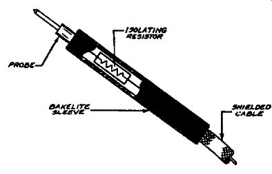
Fig. 12-3. The special test probe makes it possible to measure d-c voltages
at any point in the receiver without interfering with the passage of the signal.
Isolation of the voltmeter is accomplished by means of the resistor adjacent
to the probe tip.
… resistor which is entirely negligible. As far as the d-c loading effect on the circuit, the input resistance of the voltmeter is equal to the resistance of the isolating resistor plus the resistance of the voltage divider; this can easily be kept higher than 10 megohms for all ranges so that the d-c loading is negligible. Note that a shielded cable is shown in Fig. 12-3; this is desirable in order to prevent stray voltage pickup. Although stray voltages are not troublesome with low-resistance voltmeters, the shielding eliminates stray voltage pickup which would otherwise be troublesome when using a high-resistance voltmeter.
We have just finished describing a type of isolating probe which makes possible d-c voltage measurements without in any way interfering with the circuit under test, but in order to operate satisfactorily, this probe must be used in conjunction with a volt meter having a high resistance. Extensive investigation has shown that an electronic or vacuum-tube voltmeter type of instrument is best suited for the purpose. As we shall see, this type of instrument has the advantage of providing high sensitivity without requiring a delicate ultra-sensitive meter. Although the potentiometer-type and slide-back-type instruments both have a high input resistance, the direct-reading type of vacuum-tube voltmeter is superior because no balancing adjustment is required each time a reading is taken.
In the following paragraphs we describe the electronic or vacuum-tube voltmeter used in the Rider Chanalyst. This volt meter has proved itself to be an extremely convenient instrument for measuring every type of d-c voltage, including control and operating voltages, without in any way disturbing the circuit under test.
The circuit of this voltmeter which is shown in Fig. 12-4 makes use of the high input resistance and amplifying properties which ...
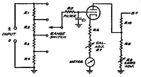
Fig. 12-4. A direct-reading vacuum-tube or electronic voltmeter suitable
for the measurement of d-c voltages without loading the circuit under test.
The large value of cathode resistance makes the calibration independent of
tube variations.
... are characteristic of the vacuum tube. The voltage being measured is applied to the control grid of the tube through the multi plier circuit, and its value is interpreted in terms of the plate current indicated by the milliammeter. When the instrument is first turned on, the zero-adjustment control is set so that the meter reads center scale or 0 volts. If a positive voltage is measured, the meter needle will deflect to the right and similarly the needle will deflect to the left for a negative voltage. As the figure shows, the multiplier circuit makes it possible to extend the range of the voltmeter in a simple manner.
So far we have not explained the use of the filter combination R5-C1 in the grid circuit of the voltmeter. It is the purpose of this resistor and condenser to prevent a-c or signal voltages from interfering with the measurement of the d-c voltage. Thus sup pose you wish to measure the d-c voltage at a point where an a-f signal is present. The filter R5-C1 removes this a-f signal and leaves only the d-c voltage which is indicated by the meter.
Actually this filter need not be completely effective because the linearity of the voltmeter circuit prevents rectification of the signal voltage from taking place, and of course without rectification the reading of the meter will not be affected. However it is desirable to include the filter to take care of extreme cases where large values of a-c voltage are present at the points being measured.
The large value of cathode resistance used in this circuit is helpful in providing degeneration so as to minimize the effect of variations in tube characteristics and line voltage on the accuracy of calibration. By this means the accuracy of calibration is made dependent upon the combined value of R6 and R7, rather than upon the tube characteristics. When the instrument is calibrated, the control R7 is set so that the correct reading is obtained on the meter scale when a standard voltage of known accuracy is applied to the instrument. Once this control has been set, it need not be readjusted unless the tube is replaced. In the latter instance, a slight readjustment of the control may be required.
It is worthwhile emphasizing that the use of this type of volt meter circuit makes it possible to use a rugged milliammeter rather than a delicate microammeter. In spite of the high input resistance, there is no possibility of overloading the circuit because the voltage is always applied across the complete divider.
The only effect of an overload is to cause grid current to flow through the filter resistor R5 so that the tube is automatically biased by this grid-current flow. The current through the meter can under no circumstances increase above a safe value and, provided the wattage rating of the resistors in the input circuit is not exceeded, no damage will be done. If the instrument is over loaded through the application of a high negative voltage, the tube will be biased beyond cut-off and the meter current will simply drop to zero.
We have already explained that when no voltage is applied to the instrument, the pointer reads center-scale or zero volts. This center-zero arrangement is a very great convenience as has been proved by numerous reports from servicemen who have used this type of instrument. In operation, it is only necessary to clip the ground of the instrument to the chassis of the receiver and any voltage--whether positive or negative--can be measured without switching leads. Whether the voltage is positive or negative with respect to the chassis (or any other suitable reference point) will be indicated by whether the deflection is to the right or to the left. This convenience in use has been found to more than out weigh the fact that the use of a conventional left zero provides a longer scale.
There is one precaution which must be observed in using any type of vacuum-tube voltmeter and this precaution is that the instrument ground must always be attached to the chassis or other ground point in the receiver. For example, if the bias at the grid of a type 2A5 tube were being measured, an incorrect reading would be obtained if the ground lead of the voltmeter were connected to the grid and the probe were connected to the chassis. If this were done, leakage between the instrument ground and the receiver chassis, as well as stray a-c voltage pickup resulting from the instrument "floating," would cause a considerable error in the reading. With the center-zero voltmeter this condition is never encountered because the instrument ground is connected to the receiver chassis regardless of whether a positive or negative voltage is being measured. The polarity of the voltage is indicated automatically as we have explained.
In line with the above explanation, it will easily be understood that the test leads cannot be switched when using a vacuum-tube voltmeter. For this reason the "left-zero" type of vacuum-tube voltmeter is not suitable for general service work unless it is provided with a polarity switch so that no switching of the test leads is required. In the latter case, a balanced circuit must be used and the polarity switch must reverse the connection of the meter to the circuit; it should under no circumstances be arranged so as to reverse the test leads.
By way of summary, we can draw the following conclusions: (1) the center-zero type of voltmeter is best adapted to service work because of the ease and rapidity with which positive and negative voltages can be measured; (2) the full-scale or left-zero type of instrument is not suitable for the measurement of negative voltages unless it is provided with an internal polarity switch; (3) even where a polarity switch is provided so as to make available the full-scale length, the center-zero circuit still has the advantage that no switch need be operated when measuring either a positive or negative voltage.
Throughout this book you undoubtedly have observed the fundamental approach which signal tracing makes to the problem of receiver servicing. And so it is not surprising to find that the instruments which make the tracing of the signal possible are every bit as basic as the method itself-as the signal itself. A well designed signal-tracing instrument has a long and useful life. It will not become outmoded by changes in the system of servicing. As long as the many stations throughout the country remain on the air, as long as intelligence is transmitted by the signals we know today-just so long will this equipment remain useful. Signal tracing is indeed as fundamental to servicing as the signal is to radio communication.