AMAZON multi-meters discounts AMAZON oscilloscope discounts
IN THE preceding sections we have discussed the manner in which the various receiver tubes and circuits function so as to provide a broad, general foundation for the application of signal tracing. Once we understand the purpose of each tube and circuit and know how they should perform when a signal is present, we can readily tell by tracing this signal just how well each is doing its assigned task. We can make these tests circuit by circuit, stage by stage, along the natural path of the signal from the antenna post to the voice coil. When we reach a point along this signal path where the signal is not as it should be, we know that some component of the receiver which influences the operation of that particular tube or circuit under test is not properly performing its assigned function. No matter how well the stages which follow are operating, if the signal is defective at the point under test, succeeding stages merely amplify the defect. Thus our search for the cause of defective operation is limited to tests of those few components which influence the signal at the point where the signal first becomes affected and not to a time-wasting, haphazard check of all receiver components.
These signal-tracing tests can be made quickly, as fast as you can move the test probe from one point to another, and are applicable to any receiver of any type, age or description, no matter what kind of tubes are employed nor how many elements are used. Further, this system can be used to embrace major sections of the receiver with a single test. That is, you can touch a probe to a given test point and immediately isolate the trouble to a section of the receiver either ahead of or following the second detector. A simple preliminary test identifies major troubles in the power supply circuit. Once the defect has been localized to one section of the receiver, the fundamental stage-by-stage tests can be applied until the point where the signal is first affected is located. Tests of a few individual components then serve to isolate the fault. It is as easy as that!
Preliminary Tests
Before we proceed with our signal-tracing tests, we must make certain that the receiver is in condition for testing. Obviously, if there is a major short circuit or an open circuit in the power supply system, the voltages on all tubes will be seriously altered or totally absent. Under such conditions, attempting to operate the receiver while making signal-tracing tests may result in damage to some components which have not already been affected.
A preliminary test of the power consumption of the receiver will immediately reveal any serious condition of this type. This need not be a precision measurement of the wattage consumed by the receiver; if any major short or open circuit exists in the power supply, the power consumption will be far above or below normal.
Small variations from normal do not concern us, since they do not interfere with the signal-tracing procedure.
The power consumption test may be made with a wattmeter or wattage indicator. To avoid damage to the wattmeter due to overload, the power supply of any receiver which blows fuses or in which the power transformer overheats should be immediately checked for short-circuits before a power consumption test is attempted. The power test may also be made by a current measurement method which may be interpreted in terms of watts by calibrating the instrument on a basis of the average power factor encountered in radio receiver transformers. This latter method has the advantage of speed, convenience and a safety factor which eliminates any possibility of damage through accidental overload in normal use.
This preliminary test is particularly advisable when the receiver under test is weak or inoperative, since such troubles frequently result from breakdown of the power-supply system.
It is also good practice, particularly with older receivers which are brought in for servicing, when the receiver is noisy or oscillating, to clean and tighten the gang-condenser rotor wipers, and to make certain that all grounding and other contacts are mechanically and electrically good before proceeding with signal-tracing tests. Noisy controls may cause intermittent operation; these and other obvious troubles should be first corrected.
The Signal Source
A good test oscillator will be needed for most signal-tracing tests. Such an instrument provides a signal which can be con trolled as to strength and frequency and also permits a steady modulating voltage. However, in making aural observations of distortion in receiver circuits, a broadcast signal is preferable because it is easier to note distortion in music or speech than on the single-tone modulation which is so universally used with test oscillators. In using an oscillograph for distortion testing, the single-tone signal is necessary, since the departure from a pure tone is readily noted on the oscillograph screen while a varying complex tone would be impossible to check. For gain-per-stage measurements in audio-frequency circuits, a steady modulation is likewise essential.
In checking for noise, hum, oscillation, and other troubles which are present when no signal is being fed to the receiver, the noise, hum or oscillation itself constitutes the signal and is traced in the same manner. In such cases, you do not need an external signal source.
The test signal frequency should be adjusted to some point near the low-frequency end of the standard broadcast band, such as 600 khz. If some local broadcast signal causes interference when the test oscillator is connected to the receiver and the set is tuned to 600 khz, then the test oscillator may be readjusted to a point either higher or lower in frequency, where no interference occurs.
It is apparent that a signal-tracing test at a frequency within the standard broadcast band is applicable even to an all-wave receiver, for the purpose of trouble localization. If the trouble is common to all bands, then it may be localized by testing on the standard broadcast band. If the trouble is present only on a short-wave band, then it must be due to some defect in the r-f, mixer or oscillator sections, since all other sections of the receiver function the same on all bands. The oscillator and mixer sections may be separately checked, thus narrowing the search for the defective component to the few remaining parts in the r-f section.
A test signal frequency in the vicinity of 600 khz is chosen be cause the gang condenser tuning capacity will be high at this frequency and the slight additional capacity which is added when a test probe is connected to the circuit will cause negligible detuning effect.
A dummy antenna, such as is recommended for alignment purposes in servicing, is desirable though not essential for signal tracing. A small, fixed condenser of the capacity recommended for aligning by the manufacturer of the receiver under test is satisfactory.
Signal Tracing in Inoperative Receivers
Now, let us assume that we have before us on the test bench an inoperative receiver. Since the receiver will not reproduce any signal which is fed to its input circuit, we know that at some point along the normal signal path, some defect exists which causes the signal to disappear. This trouble may be present in the very first circuit we test; in that case, no matter how well stages which follow may be performing, the signal will not be passed along to them. Again, the trouble may occur at the fourth or fifth test point, or even at the last point of test. Then we shall find the signal normal at all preceding points along our test path.
Our signal-tracing tests continue stage-by-stage as long as we find a normal signal present at each test point. But when we reach the point where no signal is present, we check the components which affect the signal at that point until the defect is located. This stage-by-stage test enables us to uncover many faults which otherwise might pass unnoticed, since we can make certain that each tube and circuit is performing as it should be fore proceeding to the next test point.
In Fig. 9-1, we show a partial schematic of this receiver which we are to test by signal tracing. This is a diagram of a conventional a-c superheterodyne employing an r-f stage, a combination mixer-oscillator, one i-f stage and a dual-function second detector and avc diode. This receiver normally operates over the standard broadcast band, from 540 khz to 1700 khz. Variations of this circuit will be discussed later.
Since this receiver is inoperative, we shall assume that a watt age consumption test has already been made and has shown that no serious trouble exists in the power supply. Therefore we can apply our signal-tracing tests. Connecting our test oscillator leads to the antenna and ground terminals of the receiver, we tune both the receiver and the test oscillator to 600 khz. We make ...
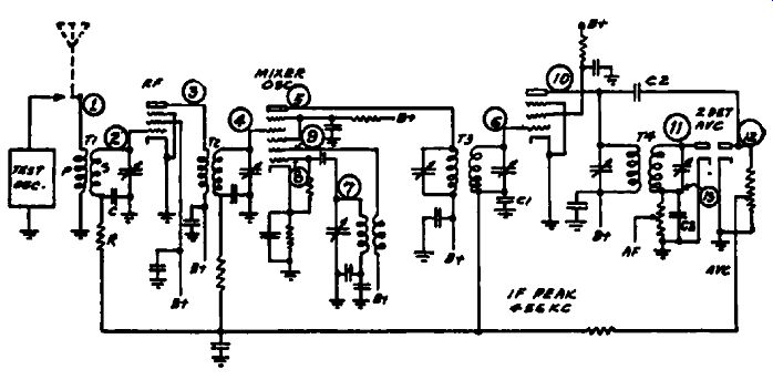
Fig. 9-1. Partial schematic of a typical receiver which is analyzed in the
text from a signal-tracing viewpoint.
... certain that the signal is actually being applied to the receiver by placing the isolating probe of our tuned v-t voltmeter upon the antenna terminal and tuning the voltmeter to the test signal frequency. The test-oscillator attenuator is then adjusted until an indication is obtained on the tuned v-t voltmeter output indicator.
The indication so obtained should be one that can be readily duplicated; if a channel "eye" is the indicating device, the eye should just close. If a meter indicator is used, the pointer deflection should be noted. This indication is termed the "reference level" and will be required for gain-per-stage measurements.
If we have previously used the test oscillator and tuned v-t. voltmeter on a normally operating receiver, we know just about where the test-oscillator attenuator should be adjusted to produce this reference level. It is possible that when we connect the test oscillator to an inoperative receiver we shall not be able to obtain sufficient signal output from the test oscillator to produce this reference level. Let us see what could cause this condition.
Examining the diagram, we note that the test oscillator is sup posed to be connected across the antenna and ground terminals of the receiver, which in turn are across the primary of the antenna transformer. Now, if this antenna coil is shorted or the antenna post has become grounded in some manner, we shall be unable to obtain our desired reference level. Therefore, the input to the receiver is short-circuited and this trouble must be cleared before the receiver can operate.
If the antenna transformer primary circuit is open, then we shall obtain our reference indication when checking the signal at point 1, but this signal will not be present at point 2, which is the next point of test along the natural path of the signal. The test at point S may be made by placing the test probe either on the control-grid cap of the first r-f tube or on the stator of the tuning condenser. The latter test point is more conveniently accessible when the receiver employs single-ended tubes, such as the 6SK7. At point S, the signal should be stronger than at point 1, since there is a voltage step-up in the antenna transformer. We can measure this gain in signal strength, but in the case of an in operative receiver we are primarily interested in finding the point where the signal disappears completely and not in the actual gain.
Absence of the signal at point :e could be caused by a shorted tuning or trimmer condenser, control-grid to cathode short in the r-f tube, or open-circuited antenna transformer secondary. If the signal is absent at this point, we check this portion of the circuit by visual examination and ohmmeter measurements until the fault is located. If the signal is present, we continue tracing the signal.
The next point of test may be either point S, the r-f tube plate, or point 4, the mixer control grid or the stator of the tuning con denser. The latter point is usually more accessible. If the signal is absent at point 4, we can check back to point 3. If present at point 3, then the trouble must be in the mixer input circuit, and could be caused by defects similar to those enumerated above.
No signal at point 3 would indicate some trouble in the r-f tube circuit, such as an open transformer primary, open or shorted voltage supply to the screen grid or plate, open cathode, or some defect in the tube itself.
If the signal is present at point 4, then we may proceed to check the set oscillator at point 7 in the manner described in Section 5.
The oscillator signal frequency should be 1056 khz when the receiver is tuned to 600 khz, thus combining with the incoming signal to produce the required intermediate frequency, 456 khz. If the oscillator is functioning properly, signal tracing continues by testing the i-f signal at either point 5 or point 6, followed by tests at point 10 and point 11. Since the intermediate signal frequency is 456 khz, the tuned tube voltmeter should be adjusted to this frequency when checking the i-f amplifier circuits.
Sectional Trouble Localization
If the i-f signal is present at the second detector plate, this is conclusive evidence that the r-f, mixer, oscillator and i-f sections of the receiver are in operating condition. When the receiver under test is inoperative, such as we are considering now, presence of the i-f signal at point 11 immediately localizes the trouble in the detector or a-f system. By the same token, absence of the i-f signal at point 11 indicates that the source of trouble exists in or ahead of the second detector. For rapid trouble localization in inoperative receivers, it is of ten convenient to check the signal at point 11 first, thus confining stage-by-stage tests to a limited number of stages. This test is applicable to any superheterodyne receiver, whether or not avc is employed.
In receivers employing ave, a measurement of the avc voltage which should result from a strong signal applied to the receiver input can likewise be used to localize the cause of failure to operate. Failure to obtain an avc voltage reading indicates that stage-by-stage tests of the sections ahead of the avc tube are necessary, while the presence of avc voltage indicates that all sections ahead of the avc tube are functioning. Signal tracing, in the latter case, can then start at the second detector.
Tracing the A-F Signal in Inoperative Receivers
Now that we have followed the signal through the r-f, mixer and i-f stages to the second detector, the next step is to trace the signal through the audio system. A typical detector-audio sys- tern is shown in Fig. 9-2. The audio signal should first appear across R1 and R2. To test this signal, we shall require a test instrument or channel capable of indicating a-f voltages and having an input impedance which is high in comparison with that of the circuit under test. Suitable apparatus for the purpose is described in Section 12.
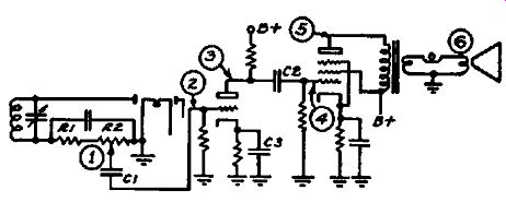
FIG. 9-2. A typical second detector-audio system. Signal tracing in this circuit
is discussed in the text.
The normal path of the audio signal corresponds to the numerical order of the numbered points on the diagram, Fig. 9-2. To trace the audio signal, place the a-f probe on point 1, making certain that the volume control is at maximum. If no audio signal is present, (indicated by failure of the test instrument to show a reading) , check the components in this circuit. If the signal is present at point 1, continue signal tracing by placing the probe on point 2, thus checking the signal transfer through the a-f coupling condenser C1. Absence of the signal at point 2 indicates an open circuit, since a short-circuit would likewise eliminate the signal at point 1.
At point 3, the signal will normally be amplified and will be so indicated on the a-f test instrument. The amount of amplification or gain which thus results is of no consequence for this test, since our primary concern with an inoperative receiver is in finding the point in the normal signal path where the signal first disappears, and not the relative strength of the signal at the various test points. When this desired point is reached, we test the components affecting the operation of that particular circuit under test until the defective component is located, just as was described in signal tracing through the r-f and i-f sections. At point S, absence of the a-f signal might indicate an open plate resistor, an open cathode resistor or a grounded plate in that specific stage.
The same reasoning applies in signal testing at any other of the numbered test points in the amplifier circuit. If the signal is present even at the last test point, 6, we know the speaker circuit is at fault, since no sound results.
Signal Tracing in Weak Receivers
If the receiver operates but the sound volume is below normal, we know that the signal must be present at all points along its normal path but that some portion of the set is not functioning at full efficiency. Our first test, as with inoperative receivers, is to measure the wattage consumption. Power supply overload, resulting from a short-circuit in some portion of the voltage distribution net work, will be indicated by excessive wattage consumption, if of sufficient magnitude. Minor breakdowns, such as by-pass condensers in resistance-capacity filters, will not cause sufficient increase in power consumption to be readily recognized in this preliminary test, though such breakdowns are quickly detected by signal tracing. If the power consumption is excessive, the first step is to check the power supply system. If no excessive wattage reading is obtained, we trace the signal along the same path as for inoperative receivers.
In tracing the signal in an inoperative receiver, our interest is confined to determining whether or not the signal is present at each test point. In weak receivers, however, we are interested in the strength of the signal at each of these test points. We know that r-f, i-f and a-f amplification, and mixer conversion gain in a superheterodyne receiver, are determining factors in the ultimate strength of the signal which is fed to the speaker. Therefore our tests must include a measurement of the gain which occurs in each amplifying stage. In modern receivers, precision measurements of gain-per-stage are not necessary in servicing, since the sensitivity normally available is usually considerably in excess of that actually required for satisfactory reception. When reception is weak, then it usually means that a very great reduction in gain, or even a loss, occurs in one or more amplifying stages.
Just what the normal gain per stage should be varies widely in different receivers, but the table of average gain-per-stage values given on page 279 will provide sufficient guidance to determine if any serious trouble is present in the tubes or circuits under test.
After each receiver is repaired, it is a good idea to mark the stage gain on the schematic for future reference.
Let us refer again to the partial schematic shown in Fig. 9-1.
We shall assume that the test oscillator is connected to the antenna and ground terminals of the receiver and a 600 -khz signal, modulated at an audio frequency, is being fed to the operating receiver. After tuning the set to 600 khz, the tuned v-t voltmeter probe is placed upon the antenna post, point 1, and the signal reference level is determined in the manner described before.
This reference level is noted on the channel indicator eye or meter, if a Rider Chanalyst is used, or on the indicating device provided in whatever other type of instrument is being used for this test.
When we place the probe on point B, an increase in signal strength should be indicated by the testing device. This signal amplification or gain is produced entirely by transformer action when the secondary circuit is tuned to resonance with the signal frequency. Therefore, this gain should be indicated even if the receiver power switch is turned off, since no tube amplification takes place in the antenna circuit. The gain from point 1 to point 2 will vary between 2 and 10 in home receivers, averaging around 5 If a loss, instead of a gain, is indicated at point 11, then some trouble must be present in this circuit. If the by-pass condenser C were shorted, no avc bias would be applied to the r-f tube control grid; consequently, grid current would flow when a signal voltage reached the grid. This condition would reduce the gain by loading the secondary circuit. A simple check is to turn the set off while noting the signal level at the control grid. If the gain increases appreciably, then some loading effect is taking place. A slight change in gain, while making this test, is normal because of the slight change in tube input capacitance which results when the r-f tube is not operating; this may be corrected by re-tuning the secondary circuit.
An open-circuited secondary will cause a severe loss in signal strength, though the capacity-coupling through the tube and transformer will provide a fa int signal which will be amplified and reproduced by the speaker. If the signal gain is normal at point I, we continue our tests by placing the probe at point 4. At this point, we are measuring the overall gain from point 1 to point 4, which embraces the gain in the antenna coil previously measured plus the gain of the r-t tube and T2. There should be a slight increase in signal level at point 4, above that obtained at point 2. The actual' gain will be dependent upon the strength of the in coming signal, since the r-f tube is controlled by ave. To obtain the true gain, the avc tube should be removed or the avc rendered inoperative in some other manner. When this is done, the overall gain should increase. If the gain to point 2 were 5, then the overall gain to point 4 should become 50 or more. This means that the r-f tube and circuit would contribute a gain of 10 or more. With the avc acting, and an input signal of 5 to 10 milli.;, volts at the antenna, the overall gain will range from 10 to 30 or more.
Our primary interest in checking the gain at point 4, however, is to find out if the signal strength increases or decreases at this point, over and above the reading obtained at point 2. If a slight loss is indicated, then the r-f tube and alignment may require checking. Poor tracking, however, seldom causes sufficient loss to cause weak reception since the first effect is to decrease the avc voltage, which in turn increases the gain. A severe loss, though, indicates a major defect in the operation of the circuit and war rants a test of the voltages and components affecting the operation of this circuit.
Assuming that a normal signal is found at point 4, the next step is to check the i-f signal at point 5 or point 6. This test is made by tuning the tube voltmeter to 456 khz and measuring the signal level. As a result of conversion gain in the mixer, the i-f signal should be stronger than the r-f signal at the mixer control grid. Again, the conversion gain will be decreased by avc action, and in case little or no gain is obtained, the avc voltage should be measured. (Complete information on avc testing is given in Section 7.) If a conversion loss is indicated when the i-f signal is measured at point 6, place the test probe on point 5.
If conversion gain is present at point 5, then the loss is due to some trouble in the coupling circuit. Normally, there is no gain in the i-f transformer and in many designs a slight loss is normal.
But if the signal level at point 6 is considerably below that at point 5, the circuit is not operating properly. Perhaps the trouble is simply misalignment.
(In this connection, remember that the application of the test probe has some detuning effect, which may be appreciable with some tuned v-t voltmeters in which the probe capacity is in excess of 1 or 2 u-u-f.) A decrease in the coupling between the primary and secondary coils of TS, loosening or shorting of turns in the secondary winding, loading due to grid current in the i-f tube; these are a few possible causes.
Conversion loss, as measured at point 5, the mixer plate, may result from misalignment, incorrect voltages on the mixer tube elements, open screen or B-supply by-pass condensers, low oscillator voltage, or a defective mixer tube. Another cause, often difficult to locate by other test methods, is lowering of the i-f transformer efficiency due to moisture absorption. If the possible sources of difficulty mentioned previously, have been eliminated, the i-f transformer should be checked by substitution. By signal tracing, we localize the trouble to the specific circuit.
A quick test of the screen by-pass condenser in the mixer circuit can be made without removing the condenser or unsoldering leads. This is done by placing the test probe of the tuned v-t voltmeter on the screen socket terminal and checking for the presence of the i-f signal at this point. If the screen by-pass con denser is open, a strong i-f signal will be noted; if the by-pass condenser is functioning properly, the i-f signal will be by-passed, hence little or no signal will be indicated, depending upon the sensitivity of the test instrument. In making this test, some signal pickup will be noted when the probe is held near, but not on, the screen socket terminal, due to the stray field and capacity coupling to the plate lead. This signal level should be greatly reduced when the probe is actually in contact with the by-passed terminal, though some slight pickup may still be noted. This functional test of by-pass action can be applied in any portion of the radio receiver and is particularly useful in a-f circuits, where stray pickup effects are not present.
Continuing our signal-tracing tests, we check next the i-f signal at point 10. There should be considerable amplification in this i-f stage, as indicated in the gain-per-stage values given. Therefore, the signal level should be much higher at point 10 than at point 6. Low gain can be investigated in the same manner as we have just discussed above. At point 1£, we cheek the i-f signal transfer from the plate of the i-f tube to the avc diode rectifier. Absence of any signal at point 12 would make the avc system inoperative; this trouble could be caused by a short-circuit in the avc diode plate circuit or an open-circuit in C2 or its connecting leads to the diode plate and the i-f plate.
The signal transfer to the second detector diode is checked at point 11. The loading effect of the diode on the i-f transformer secondary causes the signal level at the diode plate to be normally less than at the i-f tube plate. This step-down in voltage ranges from approximately 1.5 to 1 to 3 to 1. The i-f signal should be by-passed by C3, so no i-f signal should be present at point 13.
If CS, or it's connecting leads are open, a strong i-f signal will be noted when the i-f test probe is placed on point 13. Possible causes of low gain in the i-f stage are similar to those discussed previously and may be checked in like manner.
Tracing the A-F Signal in Weak Receivers
If tests of the r-f and i-f sections of the receiver have shown a strong signal at the second detector, then in all probability the audio amplifier is not providing sufficient gain so that the speaker can operate properly. If the speaker field is in shunt with the power supply, we can make a preliminary check for field excitation by placing a screwdriver or other magnetic metal object against the speaker core and noting the magnetic attraction which should result. If this check indicates field excitation is present, then we may proceed with gain measurements in the a-f system.
The A-F Reference Level. The first step is to obtain an a-f reference level. With the signal generator still feeding a modulated r-f signal to the receiver input, turn the receiver volume control to maximum and place the test probe of the a-f test instrument on point 1 in Fig. 9-2. Adjust the sensitivity of the test instrument to maximum and adjust the attenuator of the test oscillator until sufficient audio signal is present at point 1 to give a reference indication on the a-f indicating device.
Now move the test probe to point 2. The signal level should remain substantially the same as at point 1. If the signal is appreciably weaker, check for grid current at point 2, using an electronic or v-t voltmeter designed to measure d-c. Grid Current will cause a negative voltage to be developed at point 2, due to rectification. This condition would be caused by a shorted cathode by-pass condenser C3, or a cathode-heater short in the first a-f tube.
If the signal is normal at point 2, place the a-f probe on point S. If the first a-f tube is a high-mu triode, we should expect a gain of about 30 at this point. (See Table of Average Gain-per Stage Values.) Low gain at this point could be caused by a defective tube, incorrect cathode or plate voltage, or some trouble in the plate load circuit. A shorted coupling condenser C2 could cause this trouble, since then the plate voltage would be applied to the power tube grid, causing grid current and thus loading the output circuit of the a-f tube.
The a-f signal at point 4 should be substantially the same as that at point 3. A severe drop in signal voltage would result from a high-resistance joint in the coupling condenser lead connections or at other junctions between points 3 and 4. This condition could likewise be caused by a shorted cathode bias on the power tube, resulting in grid current and rectification of an applied signal. A gassy power tube would also cause a decrease in signal level at point 4. Grid current due to rectification causes a voltage drop in such direction that the power tube grid becomes negative with respect to the grid return point; grid current due to gas causes the grid to become positive with respect to the grid return point.
If the signal is normal at point 4, check the signal level at point 5, the power tube plate. The signal should be further amplified at this point. Normally, the gain will range from 8 to 20 when pentode power tubes are employed. Decreased gain will result from faults in the power tube, incorrect voltages, short-circuited turns in the output transformer primary or a shorted secondary winding.
The maximum signal voltage is developed at the output tube plate. This signal voltage is stepped down by the output trans former, since the speaker voice coil is a low-impedance circuit.
Therefore, the signal voltage at the voice coil is much lower than at the plate. A voltage step-down of' at least 25 to 1 is normal, when checking from a power pentode tube plate to a 10-ohm voice coil. Transformer losses, which are especially high in low-priced receivers, will lower still further the voltage at the voice coil.
If the signal is normal even at the last test point, the trouble must be in the speaker voice coil in its connections to the output transformer secondary, or in the field.
Tracing Noise
When noise is present in a receiver, the noise is our signal and we require no test oscillator signal. We trace the noise just as we would trace a radio signal, with the object of finding out just where, along the normal path of the signal, the noise first appears.
It is better to trace noise by means of an aural test, by plugging phones in the output jack of the test instrument, since the character of the noise heard in the phones can be compared with that reproduced by the speaker and the noise can then be definitely identified.
Referring again to Fig. 9-2, the test probe is placed on each test point in numerical order until the presence of noise is indicated. In r-f and i-f sections of the receiver, the tuned v-t volt meter is used, while for power-supply and a-f checking, the a-f v-t voltmeter is employed. If noise is found at the plate of an amplifying tube, check the noise level at the B-plus terminal. If the noise level is the same at both points, the power supply should be checked for noise. If the noise level is high, fluctuating voltages will result which will cause noise in all stages of the receiver.
By checking the power-supply components, the defective component or connection can be located.
In receivers employing avc, it is often possible to make a general localization of the noise by simply turning the volume control from maximum to minimum setting and noting if the noise level changes. If the noise disappears with the volume control at minimum setting, then the trouble is not in the power-supply section which feeds the a-f tubes. If the noise is equally loud at both volume control settings, then the trouble is in the a-f or power-supply sections.
If noise is found at the plate terminal of a socket but not at the grid, the tube may be at fault; this can be checked quite simply by substituting another tube. In transformer-coupled a-f stages, the interstage transformer occasionally may cause noise due to electrolysis or other defects. This trouble is readily localized, once the tube has been eliminated as a possible cause. When the noise is not present at the tube grid, but is noted at the plate, check the noise level at the B plus and plate terminals of the transformer primary winding. If the noise is much stronger at the plate, the transformer is at fault. If the noise is equally strong at the B plus and plate terminals, the trouble is not in the transformer. The secondary circuit may be checked in like manner. This same type of test is applicable to r-f, i-f and a-f transformers.
Tracing Hum
The cause of excessive hum is likewise located without the use of a test oscillator. Either headphones or the cathode-ray oscillograph may be plugged into the a-f test instrument output jack.
The relative hum levels at various points may then be deter mined, thus checking the efficiency of hum :filtration circuits.
Since the cause of excessive hum is most likely to be found in the power-supply circuit, it is best to start testing at its point of origin-at point 1 in Fig. 9-3. At this point, the hum level should be highest and at all subsequent test points in the filter circuits the hum level should decrease.
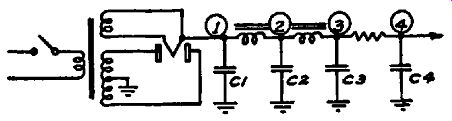
Fig. 9-3. The hum levels in this power supply circuit are discussed in the
text.
In tracing hum, place the a-f test probe on point 1 and note the hum voltage registered on the test instrument indicator or adjust the input control of the test instrument until a moderate hum level is heard in the phones or indicated on the oscillograph, depending upon the method of observation used.
When the probe is moved to point 2, the hum level should be lower. If not, check the filter condenser C2 and if necessary the first filter choke. An open condenser or a shorted choke could cause this trouble. Severe overload of the power supply may likewise cause excessive hum; this condition will be revealed by a power consumption test which should precede a hum signal-tracing test.
Continue testing until a point in the filter circuits is found where no appreciable reduction in hum level occurs. Checking components at that point will quickly locate the trouble.
It should be noted that the hum level in midget receivers is normally considerably higher than in console sets. In the former, the speaker and baffle are so small that a higher hum level is permissible since it will not be reproduced efficiently.
The foregoing discussion covers the location of hum troubles in the main section of the power-supply high-voltage filter circuit.
Hum which arises from defects in such filter systems is general throughout the receiver and objectionable whether or not a signal is being received. A similar effect will result from defective or improperly-adjusted hum balancers in receivers employing older filament-type tubes. Such devices, if present in the receiver under test, should of course be adjusted before proceeding with the tests.
If adjustment does not affect the hum level, each hum balancer should be checked. This can be done by testing for shorts or opens with an ohmmeter.
Most of the principal remaining causes of hum, which result from tube defects such as cathode leakage, shorted or open elements, poor ground connections, induction hum, shorted hum bucking coils, and leaky coupling condensers can be localized by following the procedure for tracing noise. Carrier hum can be localized by feeding an unmodulated signal from the test oscillator and also tracing as for noise. The line by-pass condensers should also be checked. Also check the grounding of the power-transformer electrostatic shield, if the transformer is equipped with a shield.
Tracing Distortion
The signal generator or a broadcast signal will be required to test for distortion; likewise headphones or a cathode-ray oscillograph. If headphones are used, then a broadcast signal is preferable, since distortion of music or speech is more apparent than on a 400-cycle modulated signal. Alternatively, a signal generator modulated by recorded music or speech from an electrical pickup and amplifier may be used for headphone distortion tracing. If a cathode-ray oscillograph is available, single-tone modulation as supplied with most test oscillators is essential. This modulation should be substantially free from distortion.
Distortion Tracing with the Oscillograph (R-F and I-F Circuits). Let us first consider the application of the tuned v-t voltmeter in connection with the oscillograph for distortion tracing. The receiver is set up for test in the manner already de scribed for signal tracing. Instead of checking the signal level at each test point, we examine the waveform of the signal as it passes from stage to stage. This waveform is compared with an initial image, representing that of the signal at the receiver input.
Should the two waveforms differ, some receiver circuit is adding distortion. Components affecting the operation of the receiver, at the point in the normal signal path where distortion is first noted, are then checked until the trouble is located. By using the oscillograph in connection with the tuned v-t voltmeter and the isolating probe, it is possible to test for distortion in tuned circuits without disturbing the circuit under test.
With the test oscillator feeding a 600 -khz modulated signal to the receiver input, our first step is to obtain our initial ref ere nee waveform. The oscillograph is connected to the output jack of the tuned v-t voltmeter, the test probe of the latter is placed on point 1 of Fig. 9-1 and a strong, modulated signal is fed to the receiver. The oscillograph vertical-amplifier gain control is then adjusted until an image of convenient height appears. The horizontal sweep is then adjusted until the wave is synchronized.
This is the initial reference waveform.
We can now check the signal waveform at any point in the r-f or i-f system. To save time, it is convenient to test first at readily accessible points, such as the control grid of each tube in the r-f, mixer and i-f sections. At each of these test points, the signal should become progressively stronger. Therefore, the image on the oscillograph will correspondingly increase in height.
DO NOT change the oscillograph amplifier adjustments; maintain an image of constant height by readjusting the input controls to the tuned v-t voltmeter or by decreasing the signal from the test oscillator, if the receiver under test is not equipped with ave. This is done to avoid overloading of the tuned v-t volt meter. It is desirable to maintain a fairly strong signal, when the receiver employs ave, since distortion is often caused by defective avc action and this condition will not be evident on weak signals.
To proceed with our testing, place the test probe on the input to the following stage at point 4. After adjusting the oscillograph image height, examine the image for distortion and note if the image is perceptibly different from that of the initial reference waveform. If regeneration is present, or if the input grid is drawing current, the waveform will be altered. Other defective conditions can likewise cause distortion at this point. Checking avc voltage, tube voltages, wiring and components affecting the operation of this stage will reveal the cause.
Distortion Tracing with Headphones (R-F and l-F Circuits). The procedure for tracing distortion with headphones in place of the oscillograph is substantially the same as that described above. Our initial reference signal should be a weak but clear signal in the headphones, as picked up at the receiver antenna post when the set is connected to a good antenna and a broadcast program is being received. If the set employs ave, the volume control should be set at minimum while checking the r-f and i-f systems, to avoid masking the signal by the operation of the loudspeaker. Alternatively, the speaker voice coil circuit may be opened or shorted. The latter will be desirable when a set without avc is being tested and for a-f system tests.
Testing follows the usual signal-tracing order. The character of the signal at the point on which the test probe is placed is compared with that at the antenna post by simply replacing the probe on the antenna post from time to time, and readjusting the input controls of the tuned v-t voltmeter to keep a constant signal level.
Distortion Tracing (A-F Circuits)
To localize distortion in a-f systems, the a-f v-t voltmeter or channel is used in connection either with headphones or an oscillograph as a distortion indicator. The reference audio signal is developed first across the diode load and should be observed at a point corresponding to point 1 in Fig. 9-2, in the receiver under test. This a-f signal should be of sufficient intensity to be clearly audible in headphones connected to the output of the a-f testing device.
If the reference a-f signal is distorted, then there is trouble in the circuit under test or in the character of the modulated signal produced by the test oscillator. The test oscillator signal may be checked by noting the character of the modulation as indicated by a test in the r-f system of the receiver, as described in r-f and i-f testing procedures given before. If there is slight distortion in the test oscillator signal, this will not preclude its being used for test purposes. We need merely to note any increase in distortion which occurs during the signal tracing tests.
If we have our test probe on point 1 in Fig. 9-2 and we have determined that distortion is present, let us see what the cause might be. We note that point 1 is coupled to point 2 by means of the coupling condenser C 1. Then any distortion which may be present at point S will likewise be noted at point 1. If the cathode by-pass condenser C3 were shorted, then there would be no grid bias on the first a-f tube. Consequently, any a-f signal applied at point 2 would cause the grid to draw current on the positive half of the signal wave, thereby causing distortion. If there were no plate voltage on the first a-f tube, the same effect would be noted; for then there would be no plate or cathode Current, therefore no voltage drop across the cathode resister would appear and consequently there would be no grid bias voltage for the first a-f tube. So distortion results, just as in the preceding case.
The same condition occurs when the a-f test probe is placed on point 3. Any defect which causes the power-tube grid to draw current in this type of circuit will cause distortion at point 3 as well as at point 4. In any case where distortion is noted, it is well to check for grid current, using a microammeter or an electronic voltmeter. Care should be taken that the circuit is not being overloaded by using too high a test signal voltage. In such cases, grid current will show even if the circuit is normal. If the cathode bias or the grid-bias voltage is normal, then the tube is being overloaded. If the tube is gassy, a positive rather than a negative voltage will appear at the power tube grid, with no signal input. This voltage is positive with respect to the grid return point and tends to buck the normal negative bias; there fore it limits the signal voltage which may be applied at point 4 without causing distortion.
Another cause of a positive voltage at point 4 is leakage in CS. A simple method of differentiating between these two causes of positive voltage at this point is to connect an electronic or v-t voltmeter to point 4, with the set turned off. When the set is turned on, if the positive voltage is the result of condenser leak age, then the voltage will appear as soon as the receiver power supply operates; if the voltage is due to gas, it will take some time to reach a maximum, usually several minutes.
Tracing Oscillation
Oscillation may occur in either the r-f, i-f, or a-f sections of the receiver as a result of incorrect operating conditions in a single circuit or from coupling between two or more stages. If oscillation occurs in a single r-f stage, it may appear that the entire receiver is oscillating since the resulting r-f oscillation is heterodyned by the set oscillator, passes through the i-f stages, and often has sufficient amplitude to affect the operation of the a-f stages. Oscillation in a single i-f stage will likewise affect, the entire a-f amplifier and perhaps the a-f system.
A preliminary operating test will suffice to give a general localization of the oscillation. If i-f oscillation is present, it will be unaffected by the tuning of the r-f system. Thus, rotating the gang condenser over the tuning range will not affect the characteristics of i-f oscillation. If r-f oscillation is present, however, the oscillation will be stronger at one point than at another; in some cases, oscillation will be present at one end of the band but not at the other.
In some cases, oscillation occurs only when a signal is applied to the receiver. When this is the case, a test oscillator should be used to supply the signal so that the dynamic operating conditions under which the difficulty is observed, are present during the test.
Before tracing the oscillation, the usual preliminary service adjustments should be made. These have been mentioned previously and include cleaning and tightening gang condenser wiping contacts and corroded ground connection; checking tubes; and a rapid check to see that no wires are obviously mis placed. Make certain that the antenna lead does not run close to the amplifying stages or tubes of the receiver; often coupling in this manner will cause oscillation which is not present in normal operation.
Assuming that r-f or i-f oscillation is present with no applied test signal, then the trouble is localized by tuning the v-t volt meter to the approximate frequency of the r-f circuit -- 600 -khz if the receiver is tuned to that frequency-and noting where the strongest signal is picked up. If there are several r-f or i-f stages, the oscillating stage will usually develop the highest signal voltage. So the test probe is placed on each tube grid or plate until this point of highest signal voltage is located. It will usually be found that a strong signal will be picked up when the probe is held anywhere in the vicinity of the r-f amplifier, but this stray pickup will not interfere with the tests. When the probe is placed upon a signal test point, and the sensitivity of the v-t voltmeter is properly adjusted, the effect of this stray pickup is largely over come.
If oscillation is due to common coupling between stages, then the relative signal voltage due to the oscillation will not prove an accurate guide to localization of the trouble. However, if common coupling is the cause, the localization of the oscillation is usually quite simple. With the test probe connected to a signal test point in one stage, simply ground the control grid (through a large condenser, 0.1 µ.f, for instance) of each of the other stages in turn until the oscillation ceases. Coupling is then present between the tube under test and the tube with the grounded grid.
The cause of the trouble is located by checking each of the components and circuits which are common to each of the oscillating stages, with particular reference to ground connections, open by-pass condensers, misplaced leads, and loose coil shields.
Tracing Audio Oscillation
Motor-boating, or intermittent blocking, is often caused by defective decoupling of filter circuits in the power supply, by open grid circuits in amplifying stages, or by feedback due to improper placement of leads or components. To locate the cause of motor boating when present with no applied signal, ground or short circuit the control grid of one of the a-f tubes so that the trouble is no longer present. Then check the condensers in the power supply and decoupling filter circuits, following the routine described for locating open condensers. If any by-pass or filter condenser is open, the hum filtering action will be absent or greatly reduced, so a relatively high hum level will be noted at the point which is normally by-passed. Open grid circuits are most easily located by shunting a resistor corresponding to the value normally used in such circuits from each grid in turn to ground or to its normal return point. When the resistor is shunted across the open grid circuit, the trouble will disappear.
Spurious oscillations are occasionally encountered in pentode and beam-power tube output circuits. This can be checked in the same way as noise but the channel eye or meter indicator should be used rather than headphones, since the oscillations are often above audible frequencies. When the test probe is placed on the grid or plate terminal of the affected tube, a high signal voltage will be registered due to the oscillation. If the stage components are in normal condition, and substitution of another tube does not eliminate the oscillation, the filter components and especially the plate by-pass condensers should be checked.
Signal Tracing in Phase Inverter Circuits
A typical phase inverter circuit is shown in Fig. 9-4. If the phase inversion is operating properly, the signal voltages applied to each push-pull grid will be equal but opposite in phase; that …
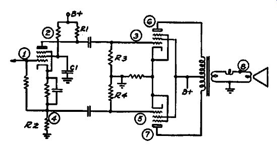
Fig. 9-4. A typical phase inverter circuit. Signal tracing in circuits of
this type is discussed in the text.
… ie, at the instant when the signal reaches a maximum on the positive half of the cycle at point 3, it reaches a maximum on the negative half of the cycle at point 5. In this type of circuit, R1 equals R2 and R3 equals R4. The coupling condensers are like wise identical.
In signal tracing, the audio signal voltage at point 2 should be measured and compared with that at point 4. These signal voltages should be equal. Minor differences in the readings are of no consequence, but a large difference means trouble in the circuit.
A change in value of R1 or R2, or of R3 or R4, would cause inequality of signal voltage; likewise, an open- or short-circuited coupling condenser between points 2 and 3, and between points 4 and 5. Slight unbalance in the signal voltages applied to the push-pull grids is usually corrected at the output plates, points 6 and ?'. While these tests do not take into consideration the phase relations between the voltages applied to the push-pull grids, the tests indicated are adequate to determine if the circuit is performing properly and to localize troubles when present.
Signal Tracing With a Signal Generator
In preceding sections, we have discussed alternative test methods in many circuits by which the test signal is introduced at some point other than the input terminals of the receiver under test. It is possible to test sections of the receiver in this manner, though most signal generators designed for service work do not permit such tests to be made with the accuracy and convenience which is possible with special signal-tracing instruments. Further, some circuits cannot be directly tested because of the loading effect of the signal generator output circuit upon the circuit under test. Gain-per-stage measurements are possible only if the signal generator attenuator is accurately calibrated, which is seldom the case with low-priced instruments. Despite these and other limitations, this method has its place in signal-tracing procedure and can be used to supplement standard signal-tracing apparatus in special cases.
In making the tests to be described, it is assumed that the signal generator to be employed is an all-wave type, equipped with a calibrated attenuator and with facilities for providing not only modulated r-f signals but also a pure a-f signal which may be varied as to voltage. Alternatively, an audio oscillator may be used for signal tracing in the a-f portions of the receiver.
An output meter, capable of reading low a-c voltages, will be required as an output level indicator. This meter should be preferably a v-t voltmeter, such as is used for a-f testing in standard signal-tracing apparatus, though any other standard output meter will suffice.
In signal tracing by this method, testing starts at the last stage of the receiver rather than at the first stage, as with standard signal-tracing apparatus. Therefore, in Fig. 9-5, which represents a typical superheterodyne receiver circuit, the test points are ...
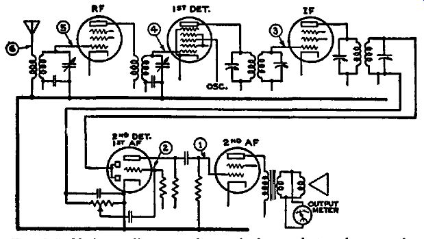
FIG. 9-5. Skeleton diagram of a typical superheterodyne receiver. The operation
of the receiver is checked by determining the signal level, at each of the
stages, which is required to produce a standard reference output at the voice
coil.
...numbered consecutively with the first test point at the last a-f grid. The output meter is connected across the speaker voice coil.
The first step is to feed an audio signal, which may be a 400 cycle note, to the last a-f grid. The attenuator on the signal generator or audio oscillator should be adjusted to give a convenient reading on the output meter, though care should be taken that the signal voltage is not so high that the output tube is overloaded.
The resulting reading on the output meter is the reference level.
Once this reference level is obtained, the signal is then fed to point 2, the first a-f grid. If the first a-f stage is operating normally, the output meter should increase. Now reduce the attenuator setting on the signal generator or audio oscillator until the original reference level is indicated on the output meter. The ratio of the signal voltage required to produce the reference level at point 1 to that giving the same reference level reading when connected at point e represents the gain of the first a-f stage.
Thus, if a 5-volt a-f signal were required to give the reference level reading at point 1, and a 0.1-volt signal produced the same output reading when the signal was introduced at point S, the gain in the first a-f stage would be 5/0.1. or 50. At point 3, the signal is to be fed to the last i-f tube grid.
Therefore it will be necessary to use an i-f signal, which must be modulated so it will be detected and amplified in the a-f amplifier and then appear across the output meter. This i-f signal must correspond in frequency to that of the i-f amplifier employed in the receiver under test. If the signal were 100 percent modulated, and the diode detector linear, then the signal gain in the last i-f stage would be determined in the same manner as that described for the a-f stage. Thus, if 0.1 volt, or 100,000 micro volts were required at point e for our reference output reading and 1000 microvolts, 100 percent modulated, were required at point 3 to produce the same reading, then the gain from point 3 to point 2 would be about 100. When the percentage modulation is lower, more signal voltage will be required at point 3 to give the same output meter reading, though the gain of the stage is the same. Thus, at 50-percent modulation, all other conditions remaining the same, 2000 microvolts would be required at point 3 when the gain is 100; at 25-percent modulation, 4000 microvolts would be required.
This dependence upon the percentage modulation in determining gain cannot be eliminated by introducing the i-f signal voltage across the diode load, because the signal generator would then be shunted across the diode load: even if a blocking condenser were used, the loading effect would be so great as to make the measurement useless. The limitations of the signal-generator output meter method of signal-tracing in diode-circuit testing apply only to such circuits in which the diode load is in series with the detector input. In all other types of detector circuits, where the detector input circuit returns to ground or in which detection takes place in the plate circuit, gain in the last i-f stage may be measured in the same manner as in any other stage.
At point 4, either an i-f signal or an r-f signal can be used. If the r-f signal is employed, the conversion gain may be determined as has already been described in Section 6. If an i-f signal is used, the result is an indication of the i-f gain of the mixer tube and circuit, but it does not establish whether frequency conversion is taking place.
The gain of the r-f stage is determined by the ratio of the r-f signal required at point 4 to give the reference output meter reading to that required at point 5 to produce the same reading. The antenna transformer gain is measured similarly by comparing the r-f signal ratios at points 5 and 6.
In making gain-per-stage measurements, it is desirable to ground the avc system, if accurate measurements are desired.
For simple signal tracing, to locate inoperative stages, this is unnecessary.
If the grid returns in any of the circuits under test are not made directly to ground in the receiver, a blocking condenser should be used between the signal generator output lead and the point under test. In a-f and i-f circuits, an 0.1-u-f condenser should suffice; in r-f circuits, a .00025-uf condenser is satisfactory. Neither of these values is critical.
In making tests of inoperative or very weak receivers, where gain measurements are not necessary for trouble localization, the test routine described above will provide a simple and quick method of localizing trouble.
Gain Measurements in Short-Wave Receivers
When the frequency range of the tuned v-t voltmeter employed for signal-tracing tests does not include short-wave bands, it is possible to combine the signal-generator gain test method with that of the straight signal-tracing method. This will not be necessary, of course, in commercial all-wave receivers, because failure to operate over a short-wave band when operation is secured on the broadcast band is conclusive evidence that the trouble is in the r-f or oscillator section. The latter is checked independently, as described in Section 5.
However, there are many special purpose receivers which operate only over short-wave bands. In such cases, r-f stages may be checked for gain by first feeding the test signal to the mixer grid, point 4 in Fig. 9-5, while the tuned v-t voltmeter is connected to some point in the i-f system, preferably the mixer plate. The tuned v-t voltmeter is adjusted to the intermediate frequency and the test oscillator to some frequency within the tuning range of the receiver. The receiver is then tuned until an i-f signal is indicated on the tuned v-t voltmeter. A reference level is obtained in the same manner as for normal signal tracing. The signal generator is then connected to point 3, without changing the signal generator attenuator setting. The signal level indicated on the tuned v-t voltmeter should increase. By readjusting the level controls on the tuned v-t voltmeter until the reference level is again obtained, the gain of the r-f stage is determined by noting the reading of the v-t voltmeter level controls. This process may be repeated stage-by-stage, by moving the signal generator test probe to points 3, 4 and 5 and the overall gain of the r-f amplifier determined.
In cases where the intermediate frequency employed is likewise beyond the range of the tuned v-t voltmeter, an audio output meter may be employed. In order to avoid overload of the detector or a-f tubes, it is well to connect the output meter at the plate of the power tube, where a high signal level is permissible, and, for the initial reference reading, to use a relatively low output-meter reading. After the gain of one stage has been determined, and the signal generator is connected to a preceding stage, readjust the signal generator attenuator until the output meter indication returned to its initial reference reading. For example, with the test signal being fed to one stage, our output meter reading may be 5 volts. If the same value of test signal is fed to the preceding stage, and the output meter reading then becomes 50 volts, the stage gain is 50/5 or 10. Now, if the gain in the next stage to be checked were also 10, the output meter reading should increase to 500 volts. This could not occur, however, because the a-f amplifier would be overloaded long before this voltage output was secured. By decreasing the signal voltage after measuring the gain of the first stage, and returning always to the initial reading of 5 volts, overload is avoided.
Signal Tracing in Tuned R-F Receivers
The method of tracing the signal in tuned r-f receivers does not differ from the procedure described for the r-f stages of superheterodynes. However, in multi-stage tuned r-f receivers, as well as many of the smaller midgets, it will be found that regeneration is present, which will affect gain-per-stage measurements. In many small receivers, regeneration is incorporated purposely to increase gain and thus to improve the sensitivity without adding additional amplifying stages. Often an adjustment to control regeneration is supplied and, before attempting any stage gain measurements it is advisable to see that this adjustment is well below the point where regeneration is evident. In multi-stage r-f amplifiers, imperfect shielding and unavoidable coupling between stages of ten causes some regeneration even when the receiver is operating normally.
In connecting a signal generator across a tuned r-f stage for the purpose of stage gain measurement, the circuit shunted is very heavily loaded so that regeneration is thereby eliminated.
Under such test conditions, the measured stage gain will be less than is actually present when the signal generator is disconnected from the circuit. Even with the isolating probe supplied with tuned v-t voltmeters, some reaction on regenerative circuits will be apparent and will affect the accuracy of stage gain measurements. From a servicing standpoint, however, these effects are of little significance. The primary object of signal tracing is not to make precision measurements of the performance of individual sections of a receiver, but to find troubles which interfere with the customer's enjoying of the set; such troubles will not be insignificant variations from normal performance-they will stand out prominently. So don't make a hard job out of the signal tracing routine-just run through the procedure quickly, watching for wide variations from expected results and not for trifles.
Receiver Alignment With Signal-Tracing Instruments
If desired, signal-tracing apparatus can be used for broadcast band receiver alignment without the usual necessity for rocking the gang condenser at the low-frequency end of the range. On short-wave bands, the oscillator operating frequency is definitely established and the danger of aligning to the image frequency is thus avoided.
Aligning Superheterodynes. In aligning receivers with ave, either a modulated or unmodulated signal may be employed. The latter is preferable, since some test oscillators provide a broad signal when audio-modulation is used.
1. Place the receiver, tuned v-t voltmeter, and a test oscillator in operation.
2. Make the receiver oscillator inoperative by connecting a clip lead from stator to rotor of the oscillator tuning condenser.
3. Connect the test oscillator to the input terminals of the receiver and tune it to 1400 khz. (Or whatever alignment frequency is specified by the manufacturer for high-frequency adjustment.)
4. With the receiver in operation, turn the tuning knob until the exact alignment frequency is indicated on the dial.
5. Place the isolating test probe on the receiver antenna post and tune the v-t voltmeter to resonance with the test oscillator signal.
6. Now clip the test probe on the mixer socket plate terminal.
7. Adjust the r-f and mixer trimmers until a maximum r-f voltage is indicated by the tuned v-t voltmeter.
8. Adjust the tuned v-t voltmeter to the intermediate frequency specified by the receiver manufacturer.
9. Now remove the shorting wire across the set oscillator tuning condenser, and, without re-tuning the receiver, adjust the oscillator trimmer condenser until a maximum i-f voltage is indicated by the tuned v-t voltmeter.
10. Tune the test oscillator, the voltmeter and the receiver to 600 khz.
11. Make the receiver oscillator inoperative (see step No. 2). 12. With the test probe still connected to the mixer plate, re-tune the receiver until the 600-khz signal voltage is a maximum, as indicated by the tuned v-t voltmeter.
13. Remove the shorting wire from the oscillator section of the tuning condenser, tune the v-t voltmeter to the i-f prescribed by the receiver manufacturer and adjust the oscillator padder con denser until the i-f signal is a maximum.
14. Since the adjustment of the oscillator padder at 600 khz will change slightly the preliminary 1400 -khz adjustment, again tune the test oscillator and the receiver to 1400 khz. Using a weak test signal, re-adjust the oscillator trimmer condenser until the i-f signal at the mixer plate is a maximum.
The r-f alignment is now complete. To align the i-f section, continue as follows: 15. Move the test probe to the first i-f plate and adjust the first i-f transformer trimmers until the channel indicates a maximum i-f signal. Reduce the test oscillator signal while making this adjustment, using just sufficient signal to note the effect of trimmer adjustments.
16. Repeat this procedure for the next i-f stage, moving the test probe to the second detector diode if there is but one i-f stage.
Continue reducing the signal voltage as the i-f stages are brought into alignment. If one or more broad-band i-f transformers are employed, shunt a 20,000-ohm resistor across the secondary before adjusting the primary trimmer. After the primary has been adjusted, remove the shunting resistor and adjust the secondary for maximum output.
Checking Tracking On Short-Wave Bands
Tracking on short-wave bands can be checked by measuring the set oscillator frequency. Follow the manufacturer's instructions for aligning, then check the oscillator frequency as follows:
1. Tune in a signal of known frequency at the high-frequency end of the band.
2. Check the receiver oscillator frequency (as described in Section 4).
3. Note if this frequency is higher or lower than the signal frequency. In most receivers the oscillator frequency should be higher. If not, it is so specified in receiver service notes.
4. Repeat the above procedure for the low-frequency end of the band. The receiver oscillator frequency should bear the same relation to the signal at both ends of the band. That is, if it is higher in frequency at one end of the band, it should likewise be higher in frequency at the low-frequency end of the band.
Note that the final adjustment of the oscillator should follow in accordance with conventional alignment procedure.
Aligning Tuned R-F Receivers
The conventional alignment procedure can be followed, using the a-f voltmeter as a sensitive output indicator. The a-f probe may be connected at any convenient point in the a-f system where the signal is present.
Localizing Defects In Intermittent Receivers
Unquestionably one of the most difficult and exasperating problems which faces the radio service industry is the servicing of intermittent receivers. When such a receiver "cuts out," the minute electrical charge resulting from touching a test prod to any portion of the receiver will of ten restore operation for an indefinite period. Even less unstable receivers, which fade slowly, are likely to return temporarily to normal if voltage measurements are attempted. And often the cause of such troubles does not affect receiver voltages. In every case, however, the signal is affected, and with multi-channel signal-tracing instruments, the particular circuits in which the signal level changes are promptly identified without disturbing the set components. The test prods are connected to key points in the receiver circuits and the level controls are adjusted to give predetermined reference levels.
Then, when the receiver becomes intermittent, the resulting changes in signal levels tell which receiver circuits are affected and the trouble is localized. Finding the defect is thus greatly simplified.
A block diagram of a typical superheterodyne receiver is shown in Fig. 9-6. The circuit includes an r-f stage, mixer, i-f, detector, and two a-f stages. To test such a receiver with a five-channel signal-tracing instrument, we divide the circuit into five major sections and monitor the operation of each section. If fewer test channels are available, this method may still be employed, but the trouble will not be as closely localized. To do this, proceed as follows:
1. Plug the receiver in the wattage indicator receptacle and note the receiver power consumption. (Or use a standard watt meter for the purpose.)
2. Connect a signal generator to the input of the receiver and feed a modulated signal of approximately 600 khz to the receiver.
3. Screw on the clips provided for each probe tip. This enables the probes to be fastened to any circuit which it is desired to test.
4. Clip the r-f probe on the stator lug of the variable condenser which tunes the mixer input circuit.
5. Similarly, connect the oscillator probe to the oscillator section of the tuning condenser.
6. Connect the a-f probe to the plate or control grid terminal of the first a-f tube.
7. Connect an electronic or other suitable voltmeter to the avc bus.
8. Tune the receiver to resonance with the signal. Tune the r-f and oscillator channels of the instrument to resonance with the circuits to which they are connected. Adjust the level controls for each channel until a suitable reference level is secured.
Note the avc voltage indicated on the voltmeter.
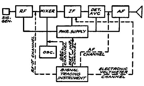
Fig. 9-6. Block diagram of a typical receiver showing how the five major
sections of the receiver can be monitored by a multi-channel signal-tracing
instrument in order to localize intermittent troubles.
We assume that the set is operating normally after these preliminary monitoring adjustments and connections have been made. Since the signal level in each part of the receiver is now monitored, any change in the operating condition of the receiver will be indicated by a change in the signal level of the stages or circuits affected.
Intermittent Operation of the R-F Section. If the cause of intermittent reception is in some circuit ahead of the mixer tube, the fallowing changes will take place:
1. The r-f signal level at the mixer will be reduced.
2. The a-f signal will also be reduced.
3. The avc voltage will change or, if the defect is of such nature that the power consumption of the receiver is appreciably changed, it will affect the wattage reading.
If a short-circuit has occurred, the wattage consumption will increase; if a voltage supply circuit has opened, the wattage consumption will decrease.
Minor changes in power consumption will of course not be indicated.
Intermittent Oscillator Operation. If the source of trouble is in the oscillator circuit, whether caused by oscillator drift, intermittent operation or irregular output, the defect will be shown on the channel indicator. Since the r-f stages are not affected (un less ave-controlled) the r-f signal voltage will not change. however, since the signal level in all other portions of the receiver is reduced, the indications will change accordingly.
When the r-f section is controlled by the avc circuit, the indicated r-f signal voltage will increase, because failure of the oscillator reduces the avc voltage on the r-f tubes.
Intermittent Operation in the I-F Stages. In case the source of intermittent operation is due to some defect in the i-f stages, the avc voltage will be decreased causing an increase in signal gain in the r-f stages, and the r-f channel will show the increase in signal voltage. The oscillator channel eye will not change; the a-f channel eye will open; the wattage indication will change as described above if the receiver voltages are appreciably affected.
Intermittent Operation in the Detector or A-F System. When the cause of the intermittent operation is the result of some trouble in the detector or first a-f stage, the a-f channel indicator will be affected. The reference levels of the oscillator channel, voltmeter, and r-f channel will not be changed unless the defect is of such nature that voltages throughout the receiver are appreciably altered. In such cases, the power consumption will like wise change, thus showing the nature of the trouble.
AVERAGE GAIN-PER-STAGE VALUES
The :figures on gain-per-stage listed below are based on the assumption that the receiver avc system is not operating. AVC action will reduce considerably the r-f, mixer, and i-f stage gains.
For comparison purposes, a weak signal should be used, or the avc circuit temporarily shorted out.
In the a-f section, for resistance-coupled amplifiers, the lower gain figures represent average gains for ac-dc receivers while the higher gains apply to a-c operated receivers.
Radio-Frequency Section: Antenna to grid of first tube . . . . . . . . . . . . . . . 2 to 10 Antenna to grid of first tube-auto radios ... 10 to 50 R-F amplifier-superheterodynes ........... 10 to 40 R-F amplifier-tuned r-f receivers ......... 40 to 100 Mixer Section: Converter grid to i-f grid (1 stage i-f amp.) .. 30 to 60 Converter grid to i-f grid (2 stage i-f amp.) . . 5 to 30 Intermediate-Frequency Amplifier Section: I-F stage (1 stage i-f amp.) .............. .40 to 150 I-F stage (2 stage i-f amp.) ............... 5 to 30 Biased Detector: Pentodes (Types 57, 6C6, 6J7, etc.). A 1.0-volt rms signal (20% mod.) at the grid will produce approximately 10 volts rms of a.f. at the plate. Higher modulation percentages will produce correspondingly higher a-f voltages. Thus 40 percent modulation will produce 20 volts rms of a.f.
Note :-A VC voltage may run as high as 40 volts, depending upon the strength of the input signal and the number of tubes under control. In general the greater the number of tubes con trolled, the lower the avc voltage for a given input signal.
Audio-Frequency Section: Medium-mu triodes, resistance-coupled: Types 6N7, 6C8 (each section) ............. 20 to 25 High-mu triodes, resistance-coupled: Types 75, 2A6, 6F5, 6SQ7, etc ............... 40 to 60 Output Pentodes: Types 6F6, 2A5, 47, 6V6, 6L6, eK6, grid-to plate gain) ............................. 8 to 20 Output Triodes: Types 2A3. 45, 71A, 6A5G . . . . . . . . . . . . . . . . . . 2 to 5
Service notes on many recent models of receivers manufactured by the General Electric Company contain valuable gain-per-stage data as well as other information applicable to signal-tracing tests.
For Models H-600, 601, 610, 611, 620 and 621, the following information is furnished in the G-E Service Notes: ( 1) Stage gains Antenna to Converter Grid Converter Grid to 6SK7 Grid 6SK7 Grid to 6SQ7 Diode Plate (2) Audio Gain
Gain 2.7 at 1000 khz 28 at 455 khz 87 at 455 khz
.05 volts, 400-cycle signal across volume control with control set to maximum will give approximately ½ watt output at speaker. Voice coil impedance equals 31/2 ohms at 400 cycles.
(3) DC voltage developed across oscillator grid leak averages 13 volts.
The stage gain ratings given above are average; variations of plus 10 percent or minus 20 percent are normal, according to the service notes.
In the above data the gain from converter grid to the 6SK7 Grid represents the gain of the converter tube and the i-f transformer at the intermediate frequency, 455 khz. This is not the conversion gain but will indicate the performance of the converter as an i-f amplifier.
The watts output may be determined by a voltage reading of the output meter when the speaker voice coil impedance is known. The required voltage reading for a given output in watts is then found by the formula, E = y RW. For example, in the above receiver data, the voice coil impedance, R, is 3½ ohms at 400 cycles; the desired watts output, W, is ½ watt. The voltage, E, which will be across the voice coil when the power output is ½ watt, is equal to the square root of (3½ times ½) . . . about 1.32 volts. This output voltage should preferably be measured with a resistance, equal in value to the voice-coil impedance, shunted across the output transformer secondary in place of the voice coil.
Average D-C Voltage Across Oscillator Grid Leak
The following tabulation gives the average d-c voltage developed across the oscillator grid leak in representative modern all-wave and broadcast-band receivers at various operating frequencies. The tabulated voltages are measured with a vacuum tube voltmeter and isolating probe, similar to that described in Section 12, and therefore represent the actual voltages at the point of test. Ordinary 1000 ohms-per-volt meters are unsuitable for such voltage measurements, due to their loading effect upon the circuit under test.
These are average values in typical receivers; variations of 50 percent are likely to be encountered in other receivers, due to differing design characteristics. Normal variations in tube characteristics will likewise affect the resulting oscillator d-c voltage.
AC-DC Superheterodynes Frequency (in khz)
600 1000 1400 6000 18,000 Eosc (d-c volts) . . . . . 11 11.5 13 10.5 5.8
A-C Superheterodynes Eosc (d-c volts) . . . . . 19
Automobile Superheterodynes Eosc (d-c volts) . . . . . 19 19 18 19 12 14 19