26. The Need for Filtering Out the Ripple
Although rectifier systems deliver an output voltage that always has the same polarity, the voltage is not suitable as DC supply for vacuum tubes because of the pulsations in the amplitude, or ripple.
The ripple voltage may be thought of as an alternating voltage that fluctuates around the average value of the DC output voltage.
The ripple voltage is not of a single frequency, as was previously assumed, but actually a fundamental frequency and a number of frequencies that are multiples of the fundamental frequency, called harmonics. Thus, the second harmonic is twice the fundamental frequency, the third harmonic is three times the fundamental, and so on. The fundamental ripple frequency may be the same as the supply frequency (for the single-phase half-wave rectifier) or as high as six times the supply frequency (for the full-wave three-phase rectifier), depending on the rectifier circuit used. The amplitude (magnitude) of the fundamental component of the ripple voltage is always larger than that of any harmonic. When the value of the ripple voltage for a particular rectifier is stated, as in Chap. 5 (Table II), it usually takes into account the amplitudes of all the major harmonics and is expressed either as the percentage of the average DC output voltage or as the ratio of the rms ripple voltage to the average DC output voltage.
Depending on the application, varying amounts of ripple may be tolerated, but it must always be a relatively low percentage of the DC output voltage. Devices for reducing the ripple voltage are known as filters. Filter circuits generally consist of capacitors, inductors, and sometimes resistors. The capacitors are always connected in parallel with the load, while the inductors or resistors are connected in series with the load.
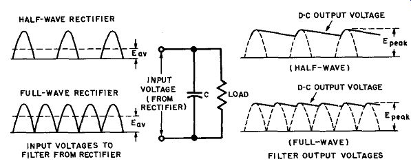
Fig. 21. Capacitor-filter waveforms with rectifier voltages applied.
27. Capacitance Filter
Consider first the action of a shunt capacitor across the load and rectifier output (Fig. 21). This is the simplest possible type of filter.
It will be remembered that a capacitor opposes any change in voltage across its terminals (the load, in this case) by storing up energy in its electrostatic field whenever the voltage tends to rise, and converting this stored energy back into current flow whenever the voltage across its terminals tends to fall. Some of the energy of the rectifier output pulses is stored in the field of a capacitor, and the capacitor discharges between the rectifier current pulses, considerably reducing the fluctuations in the output voltage (ripple). Figure 21 shows the action of the capacitor filter when either half-wave or full-wave rectifier output voltages are applied to the filter. In either case the capacitor charges up to the peak voltage of the rectifier output during the time that current pulses are delivered to the filter and load. When the rectifier output drops off to zero, the capacitor cannot discharge instantaneously; its voltage falls off slowly as it discharges through the load. During the next rectifier current pulse, the capacitor is charged again to the peak voltage, and the cycle is repeated. The only difference between the half-wave and full-wave action is that the capacitor discharges more between current pulses of the half-wave rectifier, so the DC output voltage of the latter averages less than that of the full-wave rectifier, which almost equals the peak voltage. The actual value of the average DC output voltage relative to the peak value depends on the capacitance and the amount of load current drawn.
If the capacitance is large, more energy is stored during current pulses and the capacitor output voltage remains relatively high during discharge. In contrast, if the load current is large, the capacitor discharges rapidly between current pulses and the average DC output voltage falls to a low value.
Because of its poor regulation (large output voltage drops for small load current increases) the simple capacitor filter is not used with rectifiers that supply a substantial load current. Also, the amount of ripple remaining is greater than can be tolerated in the plate supply of most electronic circuits. Finally, the capacitor filter draws large charging currents that may damage some rectifier tubes. The filter is used sometimes in the output of voltage multipliers where input chokes cannot be employed.
28. Inductance Filter
The action of a single inductor (choke coil), placed in series with the rectifier output, is illustrated in Fig. 22. This filter is usually used in combination with shunt capacitors, as we shall see later.
Essentially, any inductor opposes a change in the magnitude of the current flowing through it by storing up energy in its magnetic field when the current tends to increase, and by taking energy away from the field to maintain current flow when the voltage across the inductor tends to decrease. Hence, by placing a choke coil in series with the rectifier and load, abrupt changes in the magnitude of the rectifier output current and the load voltage are minimized. An other way of looking at the action of the series inductor is to consider that the coil offers a very low resistance (only that of the winding) to the passage of DC, while offering at the same time a high impedance to the passage of fluctuating or alternating currents.
The DC passes through, and the ripple is largely reduced.
As shown by the output waveform in Fig. 22, the load current through the filter (and hence the load voltage) lags 90° behind the rectifier output voltage and never reaches its peak value. The average DC output voltage from a single inductor is less than that from the capacitor filter, but the voltage does not fall off as rapidly with increases in load current as with a capacitor filter.

Fig. 22. Waveforms and diagram of inductance filter action.
29. Capacitor-Input Filter
More effective filtering action can be attained by combining the actions of a shunt capacitor and a series inductor in capacitance-inductance filters. Various combinations of such filters exist, but in all of them the action of the capacitors is to resist changes in output voltage by charging and discharging, as required, while the inductors oppose any changes in the magnitude of the load current through the action of their associated magnetic field.
Equivalently, the shunt capacitors may be considered to form a low impedance path to minus, and ground for the ripple voltage, ...

Fig. 23. Capacitor-input filter diagram and waveforms.
... and an essentially infinite impedance to DC. The series inductors (choke coils) can be considered to offer a low impedance to the passage of DC and a very high impedance to the ripple current.
Figure 23 illustrates a capacitor-input filter (also known as a Pi-filter) with typical component values. This circuit is characterized by a high output voltage at low current drain, the voltage being almost equal to the peak value of the transformer secondary voltage applied to each tube. (The peak value is 1.414 times the rms value.) As the load current increases the output voltage falls off rapidly (because of the capacitor discharge) and may become less than the rms value of the applied AC voltage. In other words, the regulation of a capacitor-input filter is poor.
The waveforms of Fig. 23 show the basic action of the filter.
The current pulses flowing through the rectifier tubes and filter charge up input capacitor C1 to the peak voltage of the trans former secondary. The filter input capacitor must have a rating high enough to withstand the instantaneous peak value (1.414 times the rms value of the ac) if breakdowns are to be avoided.
Between current pulses, the voltage across C1 falls off somewhat, but never reaches zero, just as in the case of the simple capacitor filter (Fig. 21). Because of the action of the choke coil (L), the voltage peaks across C1 lag behind the peaks of the rectifier output voltage (obtained without a filter). With the additional filtering provided by the coil and capacitor C2, the DC output voltage becomes essentially constant, as indicated (in exaggerated form) by the solid line in Fig. 23. Actually, a small ripple is still present in the output of the filter, which may be eliminated by adding another filter section.
By increasing the value of the filter capacitors above those shown in Fig. 23 (especially that of input capacitor C1) the ripple voltage may be decreased further and the average DC output voltage will be increased slightly. Increasing the DC output (load) current, however, increases the ripple voltage and reduces the available DC output voltage.
Bleeder. Some resistance must always be connected across the output of the capacitor input filter, even when the normal load is absent. This maximum resistance is called the bleeder resistor, and as its name implies, its chief purpose is to discharge the capacitors when the equipment is turned off. To improve voltage regulation, the bleeder resistor is usually made smaller than this maximum value, as will be explained later on.
30. Choke-Input Filter
A typical choke-input filter, consisting of a 20-henry series inductor and a 10-microfarad shunt capacitor, is shown in Fig. 24.
When the load draws no current, the DC output voltage of the choke-input filter is nearly equal to the peak value of the AC voltage applied to the rectifier, just as in the case of a capacitor input filter. This is so because in the absence of a load current no voltage drop is developed across the choke coil (L), and hence the output capacitor (C) charges up to the peak value. However, if even small load current is drawn, the DC output voltage drops rapidly to some lower value and then remains fairly constant over a wide range of load-current values. The initial sharp drop occurs because the series inductor prevents the capacitor from charging to the peak voltage when a load current is drawn. After this initial drop there is good voltage regulation of the choke-input filter.
Bleeder Resistor. A bleeder resistor connected across the filter output is generally designed to draw sufficient current for operation in the beginning of the almost constant portion of the voltage current curve of the filter output, where the voltage regulation is excellent (Fig. 26A). By placing a load across the output, the bleeder becomes useful also in preventing high-voltage surges through the power supply when the equipment is first turned on.
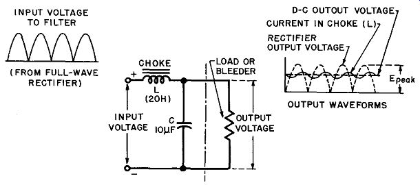
Fig. 24. Choke-input filter waveforms and schematic.
For satisfactory operation, the bleeder should draw about 10% of the rated load current.
Waveforms. The voltage and current relations in a choke-input filter are illustrated by the waveforms in Fig. 24. The load current in the choke coil lags behind the rectifier output voltage, as shown, and has a small ripple. The DC output voltage across C and the load is substantially constant, as indicated by the dotted line, and its value is somewhat less than the peak AC voltage, depending on the load current drawn. The ripple in the DC load current through the choke can be considerably reduced by increasing the value of the inductance. For an infinite inductance (the ideal case) the DC load-current waveform becomes a straight line equal to the average of the fluctuations shown in Fig. 24.
Input Inductance Requirements. For normal choke-input filter operation there must be a continuous flow of current through the choke coil. The peak value of the AC ripple current through the choke must be less than the DC output current, or the current through the choke might fall at times to zero. This condition is approximately realized by choosing the value of the input inductance (L) so that the following relation is satisfied:
L = E1
2 pi f I
... where ...E1= fundamental component of the ripple voltage
I = DC output current in amperes
f = fundamental ripple frequency in cycles
pi = 3.1416
For the practical case of a 60-cycle, single-phase full-wave rectifier, the fundamental ripple frequency is 120 cycles, the ripple voltage
E1=0.667 E (where E is the DC output voltage) and hence the above relation becomes
L= 1130 I E
... where ... E is the DC output voltage and I is the output current.
Example: What should be the minimum value of the inductance in a choke input filter if the output voltage from a full-wave 60-cycle rectifier filter system is 350 volts and the DC load current is 100 ma.?
Solution: The minimum inductance
E L = ~1~13~0~1 350 1130 X .10
3.1 henrys
Actually to assure good operation at low load currents, a larger value than the minimum inductance should be selected.
The minimum inductance given by the above relation is that value below which the choke-input filter is no longer capable of functioning properly, but at which it acts like a capacitor-input system. Note that the minimum inductance depends inversely on the load current. If the load current fluctuates over a certain range, an inductance corresponding to the lowest load-current value must be chosen to obtain satisfactory operation. Here again, a fixed bleeder resistor, drawing about 10% of the full DC output current, assures good voltage regulation and eliminates the need for excessive input inductance values.
In the next section we shall consider choke-input filter design in more detail and the minimum inductance values for various rectifier circuits (single- or three-phase) will be given.
Swinging Choke. From the relation given for the minimum input inductance, it is evident that the required inductance may vary over a wide range, depending on the load-current fluctuations.
Even with a bleeder present, the required inductance at the minimum (bleeder) current may be excessive compared to the value needed for effective hum suppression at normal load currents.
A swinging choke is designed to overcome this disadvantage by varying its inductance according to the load. The inductance of a swinging choke is high at low load currents and drops off with increasing load currents. This is accomplished by making the air-gap of the choke coil very small. At small load currents, the incremental inductance of such a choke will be very high, while at large load currents it will be sufficient to give adequate filtering.
(The incremental inductance is the inductance to the alternating ripple current superimposed upon the DC magnetization.) It is important to realize that the minimum inductance given by the previously stated relation is the incremental inductance, that is, the inductance to the AC ripple superimposed on the DC magnetizing current. As the DC magnetization decreases at low load currents, the incremental inductance of any choke increases.
Even without a swinging choke, the relation for minimum inductance at low load currents will generally be satisfied by any well-designed choke coil.
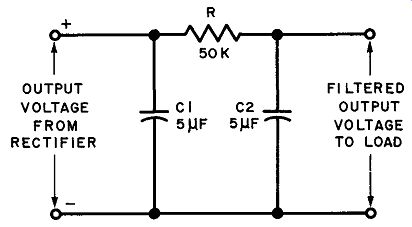
Fig. 25. Schematic of a typical resistance-capacitance filler.
31. Resistance-Capacitance Filter
When the load-current requirements are small and a moderate DC voltage drop across the filter is permissible, the inductance of a capacitor-input filter may be replaced by a series resistance. The resulting resistance-capacitance (R-C) filter is not as effective as an inductive filter, since the series resistor offers as much impedance to DC as to the ripple voltage. Some ripple is always present. The advantage of the R-C filter is that a resistance is much less expensive than an inductance. An R-C filter with typical component values is shown in Fig. 25.
Capacitance C1 in Fig. 25 is made sufficiently large to present a very low impedance to the ripple frequency, while at the same time offering practically infinite impedance to DC. The ripple voltage, therefore, prefers the shunt path through C1 to minus (and ground), while the DC is forced through resistor (R) and develops a voltage drop across it. Most of the remaining ripple voltage at the filter output is shunted to ground through the low impedance path offered by capacitor (C2), while the filtered rectifier voltage is available at the output terminals. The value of the filtered DC output voltage is substantially the rectifier output voltage developed across capacitor (C1) minus the voltage drop developed across series resistor R. Amount of Filtering. In practical R-C filters, the reactance of the shunting capacitors is always made small compared with the series resistance. Under this condition, each section of an R-C filter reduces the ripple voltage applied to its input by the following (approximate) ratio:
Reduction Factor
A-c Ripple Voltage
Across Filter Output
A-c Ripple Voltage
Applied to Filter Input
2 pi f CR
where f = the frequency of the ripple voltage component
R = series resistance of filter
C = the filter output capacitance (C2 in Fig. 25.)
When several filter sections are connected in series ( cascade), the total reduction factor is approximately equal to the product of the voltage reduction factors of the individual sections. In poly phase rectifiers, where the ripple frequency (f) is high, a single R-C section is usually adequate.
Example: Compute the ripple:; voltage reduction factor of the R-C filter shown in Fig. 25, for a 60-cycle single-phase, full-wave rectifier.
Solution: (See Fig. 25.) The fundamental ripple frequency of a full-wave rectifier is 120 cycles. According to the relation above, the reduction:
1 factor= 2,r x 120 x 5 x 10^-6 x 50,000 = 0.0053
Hence, the output ripple is only 0.53% of the input ripple.
Uses of R-C Filters. Because of their relatively low expense R-C filters are popular in a wide variety of low-current drain applications including oscilloscope power supplies, and decoupling net works in resistance-coupled amplifiers. In these applications, some voltage drop in the filter is permissible and the current drain is sufficiently low to prevent the voltage drop from becoming excessive. Whenever large load currents are required, however, the high voltage drop developed across the resistance of an R-C filter cannot be tolerated.
32. Comparison and Design of Capacitor-Input and Choke-Input Filters
The main electrical difference between choke-input and capacitor input filters is that current flows continuously from the rectifier to the filter in choke-input circuits, while current flow is an intermittent series of charging pulses in capacitor-input circuits.
The consequences of this basic difference are a higher DC output voltage, lower ripple voltage and poorer voltage regulation for a capacitor-input filter than for the choke-input type, when both are used with the same circuit and load. Furthermore, in a capacitor-input filter the ripple voltage increases with increasing load current (i.e., the filtering becomes poorer), while for choke input filters the ripple voltage is independent of the load current. Finally, the ratio of the peak current to the average DC flowing through the rectifier tubes is higher for a capacitor-input filter than for the corresponding choke-input circuit. This results in poor utilization of rectifier tubes and the transformer for capacitor-input filters.
Applications. In general, capacitor-input filters are employed when the amount of required DC power is small. This is the case in most electronic home appliances, radio sets, television receivers, and small public-address systems. Choke-input filters, on the other hand, are used whenever the amount of DC power required is large, because of the savings in tubes and transformer costs resulting from the lower peak currents. For this reason, choke-input filter circuits are exclusively used in polyphase rectifiers and wherever good regulation of the DC voltage is more important than a small increase in its value. Voltage-multiplying circuits always use capacitor-input filters, since the input capacitor is essential to their operation.
Regulation of the D-C Voltage. The regulation of a rectifier-filter system is the decrease in available DC output voltage from no-load current to full-load current. Figure 26 graphically compares the variation in output voltage with load current of a choke-input filter (solid line) with that of a capacitor-input filter (dotted line) in a typical single-phase, full-wave circuit.
It is evident from Fig. 26 that the no-load DC output voltage of both types of filters is almost equal to the rectifier peak output voltage. In both filters the output voltage drops off with increasing
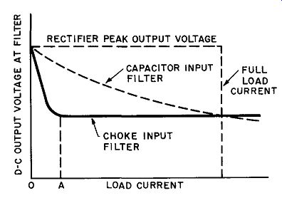
Fig. 26. Effect of load current on DC output voltage for capacitor- and choke-input
filters in a full-wave rectifier circuit.
DC load current because of unavoidable voltage drops across the transformer windings, rectifier tubes, and filter components. Note, however, that the output voltage with a capacitor-input filter continues to drop off steadily with increasing loads, while the output voltage with a choke-input filter becomes almost constant after an initial sharp drop. The reason for this difference is as follows.
In the capacitor filter, the output voltage continues to fall off because of the more rapid discharge of the filter input capacitor with increasing load currents. In the choke-input filter the output voltage drops off sharply with a small increase in load current because the choke coil prevents the shunt capacitor from charging to the peak voltage. After this drop the output voltage falls off only gradually, due to increasing tube and transformer drops.
Choke-input filters are, therefore, always operated in the current voltage region beyond point A (in Fig. 26) by a suitable bleeder resistor placed across the output of the filter.
Curves of the type shown in Fig. 26 permit determination of rectifier output voltage of a particular circuit for various loads and filter component values. Such curves are frequently presented in manufacturer's tube manuals, or the information for them may be listed in tabular form under "typical operating conditions."
L-C Filter Design.
Figure 27 shows typical examples of choke input and capacitor-input filters of one or more sections which are placed between the rectifier output and the load to obtain substantially pure DC.
Note in Fig. 27 that for design purposes each filter section is considered to be made up of a series inductance (choke coil) and a shunt capacitor. The input inductance of a choke-input filter is part of the first filter section, but the shunt capacitance (C) of a capacitor-input filter is included not as part of the first filter section, but as an integral part of the rectifier output. With the input capacitor considered as part of the rectifier, the filter sections of choke-input and capacitor-input circuits become identical. Then rectifier output and ripple voltage that feeds into the series induct ance of a choke-input filter or into the shunt capacitance of a capacitor-input filter must be determined. Now it is possible to compute the reduction in the ripple voltage in the same way for both types of filters. As stated before, the rectifier tube output voltages (for typical operating conditions) into either an input inductance or a shunt capacitor are listed in manufacturers' tube manuals.
When the reactance of the shunt capacitance of an L-C filter section is small at the lowest ripple frequency compared to the load resistance (or the reactance of the inductor that follows), which is always the case in practical filters, the reduction is the ripple voltage for a single section may be computed from the following approximate relation:
Reduction Factor = A-c Ripple Voltage Across Filter Output A-c Ripple Voltage
Applied to Filter Input
... where ...f = frequency of ripple voltage component
L = series inductance of filter section
C = shunt capacitance of filter section
4 pi ^2 = 39.48
Example: What is the reduction in the fundamental ripple voltage of a 60-cycle, single-phase, full-wave rectifier, if a capacitor-input filter of the type shown in Fig. 27B with 10 u-f shunt capacitors and a 20-henry choke is employed?
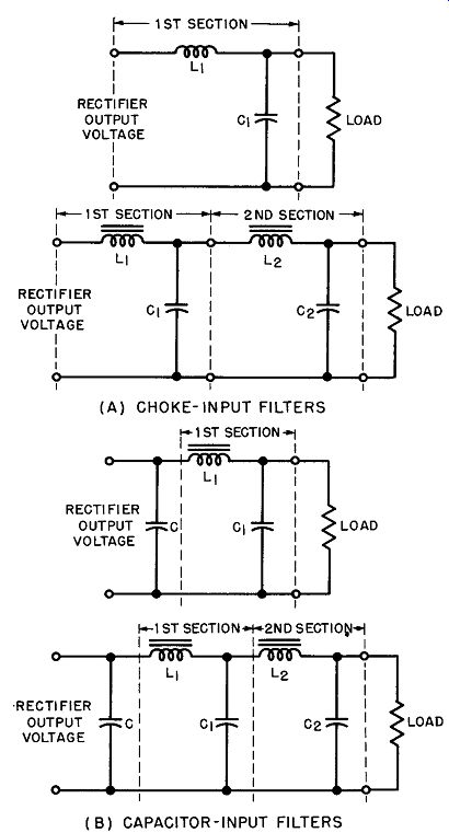
Fig. 27. Schematics of typical filter sections.
Solution: The fundamental ripple frequency (f) is 120 cycles; the reduction
factor = 1/ 39.48 (120)^2 X 20 X 10 X 10^6 - 1 = 0.0089
The output ripple voltage is only 0.89% of the input ripple voltage applied to the filter.
In the next section a number of curves will be presented from which the reduction factor for L-C filters with various rectifier circuits can be determined without elaborate computation.
33. Tuned (Resonant) Filters
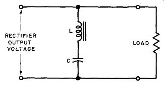
Fig. 28. A series-resonant filter circuit in parallel with the load.
By using a resonant circuit as a filter, a particular ripple frequency may be effectively suppressed. As shown in Figs. 28 and 29, either a series-resonant circuit in parallel with the load or a parallel-resonant circuit in series with the load, may be used to suppress the ripple.
In the series-resonant filter circuit (Fig. 28) the reactance of the coil and that of the capacitor cancel out at the resonant (ripple) frequency and the opposition to the ripple voltage is thus only the series resistance of the tuned circuit, which is essentially the coil winding resistance. The filter, therefore, acts as a short circuit across the load for the ripple frequency to which it is tuned, while presenting almost infinite impedance to the DC output voltage.
In contrast, the parallel-resonant filter (Fig. 29) presents a very high impedance (Q times the impedance of the coil) to the ripple frequency to which it is tuned, while at the same time presenting only the coil resistance to the flow of direct current. It effectively blocks the passage of the ripple current to the load. Small ripple currents that do get through are further by-passed to ground by shunt capacitors C' and C".
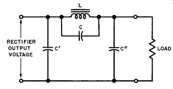
Fig. 29. A parallel resonant filter circuit in series with the load.
Since the resonant frequency (f) of either tuned circuit is approximately I /2 pi yLC, the product of inductance and capacitance for a resonant filter must satisfy the relation
I 47r2 £2 39.48 £2
... where ... L = inductance of resonant filter
C = capacitance of resonant filter
f = frequency of ripple voltage component
In the parallel-resonant filter (Fig. 29), the minimum inductance of the choke coil is usually determined by the previously discussed considerations for a capacitor-input filter, so that the value of the capacitance (C) is also fixed.
Example: What value capacitance must be connected across the choke coil of a capacitor-input filter to tune it to resonance for a 60-cycle, single phase, half-wave rectifier, if the minimum inductance for effective filter operation is 5 henrys? Solution: The fundamental ripple frequency for a half-wave rectifier is 60 cycles. Hence, hy the relation stated above:
LC 39.48 (60)2 7.04 X 10^-6
The capacitance C = LLC 7.04 X 10^-6 S = 1.41 X 10^6 = 1.41 µ.f
The disadvantage of resonant filters is that they can suppress only one of the several ripple frequency components present in the output of the rectifier. If they are correctly tuned to the fundamental ripple frequency, they will not effectively suppress the other ripple frequency components, and additional filters must be used. Also, the individual tuning of each resonant circuit is a bothersome procedure. For these reasons tuned filter circuits are seldom used in rectifier power supplies, although they find considerable application in other types of electronic circuits.
34. Review Questions
(1) What is meant by the fundamental ripple frequency and the harmonics; what is their relationship to each other?
(2) Draw a capacitor-filter circuit, explain its action and describe its ad vantages and disadvantages.
(3) Explain the action of an inductance filter and compare it with a capacitance filter.
(4) Why is a capacitor-input filter better than a single shunt capacitor? What is the maximum DC output voltage of the filter and how does it vary with increasing load current?
(5) What is a bleeder resistor and why is it necessary in the output of a capacitance-type filter? What are its other advantages in conjunction with any type of filter?
(6) Compare the operation of a choke-input filter with that of a capacitor input filter. State which filter has better voltage regulation? lower ripple voltage? higher DC output voltage? For which application is each filter best suited?
(7) What is meant by the minimum input inductance of a choke-input filter? Compute the minimum inductance for a three-phase, full-wave, 60-cycle circuit, if the DC output voltage is 400 volts and the load current is 250 ma.
(8) Define incremental inductance. How does the variation in incremental inductance of a swinging choke make it useful for choke-input filters?
(9) When is a resistance-capacitance filter practicable? Compute the ripple reduction factor of an R-C filter, using 25 µ-f shunt capacitors and a 20,000-ohm series resistor, for a 60-cycle, single-phase, half-wave rectifier circuit.
(10) Design a choke-input filter for a three-phase, full-wave, 60-cycle rectifier, so that the fundamental ripple voltage from the filter output is only 0.1 % of the input ripple. The DC voltage of the rectifier is 300 volts, the output current is 500 ma, and the bleeder current is 50 ma. (Hint: Compute first the minimum input inductance of the filter, then the value of the shunt capacitance.)
(11) What value capacitance is required to tune the filter in question (10) to parallel resonance at the fundamental ripple frequency?