18. The Need for Polyphase Circuits
Practically all alternating-current power is transmitted over three wires in a three-phase circuit. In such a circuit the voltage appearing between any two wires is 120° out of phase with the voltages appearing across the other two pairs. Each wire serves to some extent as a return wire for the other two, permitting a considerable saving in copper. This and other advantages increase the efficiency and power utilization of three-phase systems to such an extent over a single-phase supply that practically all large-scale industrial power consumers utilize three-phase power. (The ordinary house current uses one phase of a three-phase system.) Since many industrial processes require DC power, however, polyphase rectifier circuits are needed. Because of the heavy current requirements, gas-filled diodes, such as mercury-vapor tubes and ignitrons, are frequently employed in polyphase rectifiers.
When a three-phase power supply is available, advantage is taken of its high efficiency by connecting the rectifier tubes in 3-, 6-, and 12-phase circuits. All are derived from the basic three-phase supply. Two-phase power supplies and their associated rectifiers are of little interest because of their relatively low efficiency.
Despite the multiplicity of possible rectifier circuits for polyphase systems, only a few of importance in electronics will be discussed.

Fig. 16. Three-phase hall-wave delta-wye rectifier and output waveform.
19. Three-Phase Half-Wave Delta-Wye Rectifier
The simplest of the three-phase rectifiers is the half-wave delta wye circuit, shown in Fig. 16. The terms "delta" (Δ) and· "wye" (Y) refer to the configuration of the primary and secondary coils, respectively, of the three-phase transformer.
Note in Fig. 16 that the three-phase line is connected to the junctions of three delta-connected primary coils, so that the full primary voltage (E_p) of each phase is developed across each coil.
The three secondary coils of the transformer are mounted in the shape of a wye and a secondary voltage (E.) is developed across each coil or leg. These secondary voltages are 120° out of phase with each other; that is, the output sinewave of each coil is displaced in time by 120°, or one-third of a cycle, with respect to the sinewaves of the other two coils.
The circuit shown in Fig. 16 consists essentially of three separate half-wave rectifiers, one for each leg of the secondary wye, or one for each phase. The operation of each half-wave rectifier is identical to that described for the single-phase half-wave rectifier, illustrated in Fig. 5 and 6. Each tube carries current only during the positive half-cycles of its phase, or only one-third of the time. The output voltage, therefore, fluctuates at three times the AC supply frequency, as shown in the waveform of Fig. 16. This permits easy filtering of the ripple.
Although each of the rectifier tubes is only a half-wave unit, the cathode currents of all the tubes flow through the common load resistance, so the average DC load current is much higher relative to the peak current than in a single-phase rectifier. The average DC current of a three-phase half-wave rectifier is 0.826 ...

Fig. 17. Three-phase half-wave delta-zig-zag rectifier.
... times the peak current, compared to a value of 0.318 for the same ratio in the single-phase, half-wave circuit, and 0.636 for the single-phase, full-wave circuit. Because of this high average current value, the DC output voltage is correspondingly high, and as a matter of fact, it is greater than the AC rms voltage of each secondary leg by a factor of 1.17. (The peak voltage is 1.414 times the rms value; hence the average output voltage is 1.414 x 0.826, or 1.17 times the rms voltage.) Equivalently, the rms voltage across each leg (E.) of the secondary need only be 1 / 1.17 or 0.855 times the average desired DC output voltage.
20. Three-Phase Half-Wave Delta-Zig-Zag Rectifier
The circuit shown in Fig. 17, known as a three-phase half-wave delta-zig-zag rectifier, because of its configuration, is identical with the delta-wye rectifier except for the method of installing and mounting the coils in the three-phase transformer. In the delta wye circuit (Fig. 16) the rectified current flows through each secondary coil in one direction, which saturates the transformer core and effectively reduces the inductance of the winding, just as in the single-phase half-wave rectifier. This disadvantage is over come in the delta-zig-zag circuit by supplying each core with two secondary windings operating in phase opposition to each other.
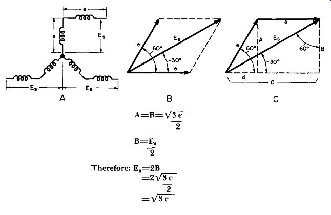
As a consequence, each leg is made up of two sections, each operating in a different magnetic circuit. These are connected in successive legs of a zig-zag arrangement to give secondary voltages phased 120° apart. Each secondary phase (En) then turns out to be the vector sum of two winding voltages that are effectively 60° out of phase with each other. It may be shown that E. equals sqr-root 3 or 1.732 times the voltage developed across each coil winding.
21. Three-Phase Half-Wave Double-Wye (Six-Phase) Rectifier
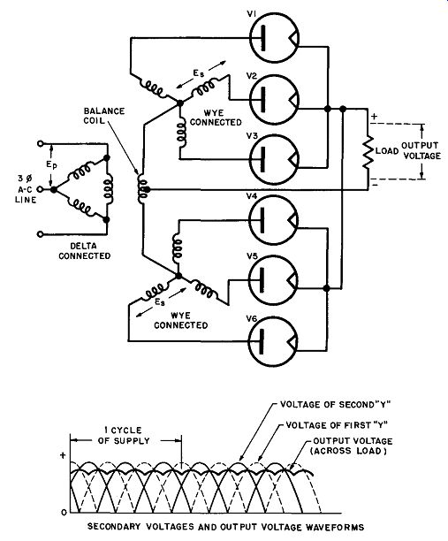
What essentially amounts to six-phase operation is obtained in the circuit shown in Fig. 18 by connecting two three-phase half-wave circuits in parallel through a balance coil (also known as interphase reactor). This results in reversing the polarities of corresponding secondary windings in the lower wye with respect to those in the upper wye. Thus, when the secondary voltage (En) of one winding in the upper wye is at maximum, the voltage of the corresponding winding in the lower wye will be at a minimum. This effectively adds three extra phases, making a total of six phases.
-----------

• In Fig. A, E. is the vector sum of two voltages of magnitude e differing in phase by 60°, as shown in Fig. B. The e vectors may be redrawn as in Fig. C. Triangle Ade forms a 30°-60°-90° triangle with sides in the proportions __/3-1-2. Triaqgle CBE. is a similar triangle with sides in the same relative proportions.
---------
SECONDARY VOLTAGES AND OUTPUT VOLTAGE WAVEFORMS

Fig. 18. Three-phase half-wave double-wye (six-phase) rectifier and waveforms.
-------

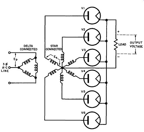
Fig. 19. Three-phase delta-star (six-phase half-wave) rectifier.
Note that the circuit of Fig. 18 requires six rectifier tubes, each acting as a half-wave rectifier for one phase, or one leg of each wye. The central junction of each wye is connected to the other through the interphase balance winding, which compensates for any inequalities in the upper and lower sections. The centertap of this winding becomes the negative terminal of the DC output voltage. The plates of the rectifier tubes are connected to the legs of the two wyes, while their cathodes are connected together.
Consequently, the cathode currents of all tubes flow through the common load resistance.
Examine the secondary wye and output voltage waveforms of the double-wye circuit (Fig. 18). As explained before, the secondary voltage of the first wye (dotted line) is at a minimum when the secondary voltage of the second wye (solid line) is at maximum, and vice versa. The same holds true for the rectified output voltages of each wye, since the half-wave rectifiers simply cut off the negative half-cycles, but do not change the relative amplitudes. There are, therefore, six fluctuations in the output voltages of the wyes for each AC supply cycle and the ripple frequency is six times that of the AC supply.
Because of the action of the balance coil, the actual DC output voltage across the load does not follow the peaks of the wye output voltages, but rather the average of the rectified wye output voltages, as is shown in Fig. 18. The peak current through each tube is only one-half of the average DC load current. The rms voltage required across each leg of the transformer secondary is still 0.855 times the average desired DC output voltage for the delta-wye half-wave rectifier circuit shown in Fig. 16. This somewhat paradoxical situation is due to the requirements of the interphase balance coil, which must insure that the individual three-phase half-wave systems (upper and lower wyes) operate independently with current flowing through each tube one-third of the time.
Note that the voltage across the balance coil is the difference between the output voltages of the individual wyes. To assure independent operation, the coil must have enough inductance for the voltage (difference) across it to give rise to a peak alternating current that is Jess than the direct current flowing through one leg of the coil. To be exact, the peak value of the alternating current in the coil must be less than one-half the DC load current.
This is the reason for the low peak-current per tube compared to the average DC load current. Note also that the direct current flows in opposing directions through the two halves of the balance coil, which means no DC saturation is present.
Example: Assume a 230-volt three-phase, 60-cycle AC line is connected to the primary of a l: I transformer operating in the double-wye rectifier circuit, shown in Fig. 18. If the average DC drawn by the load is 100 amps, what are the average and peak currents per rectifier tube, the average DC output voltage, the DC power delivered to the load, and the ripple frequency?
Solution: The average current per plate is obviously one-sixth of the DC load current, since there are six tubes. Thus, the average current per tube is 100/6=16.7 amperes. The peak current per tube is one-half the average load current, or ½ x 100=50 amperes. DC output voltage is 1 / 0.855 or 1.17 times the rms value across each leg of the transformer secondary. For a 1:1 transformer, the secondary leg voltage must be 230 volts; the DC output voltage (neglecting the transformer and tube drops) is 1.17 x 230 or 269 volts. In practice this value will he lower because of the voltage drops lost in the tubes and transformer. The DC power delivered to the load is the product of the average DC output voltage and the load current, or 269 x 100=26,900 watts. Finally, the ripple frequency is six times the supply frequency, or 6 x 60=360 cycles. This is easily made pure DC with a simple filter circuit. (See Chap. 4.)
22. Three-Phase Delta-Star (Six-Phase Half-Wave) Rectifier
The equivalent of six-phase operation from a three-phase supply can be attained by center-tapping the secondary winding of a three phase transformer more easily than it can be achieved in the double wye circuit. Refer to the single-phase, center-tapped transformer shown for the full-wave circuit in Chap. 2, Fig. 7. Such a star connected secondary will have voltages of opposing polarities across each half of a winding with respect to centertap, giving effectively a total of six phases (one for each leg of the star.) A typical three phase delta-star rectifier circuit is shown in Fig. 19.
Note that the delta-star circuit requires six half-wave rectifier tubes, one for each phase or secondary leg, just like the double-wye circuit. The output waveform is similar to that shown for the double-wye circuit (Fig. 18) and also has a ripple frequency equal to six times that of the AC supply.
Because of the absence of the balance coil the limitations with respect to the peak and average currents do not apply to the delta star circuit and the average DC load current of the latter turns out to be 0.955 times the value of the peak current per tube. The average output voltage is thus also 0.955 times the peak voltage, or 1.414 x 0.955=1.35 times the rms value (E.) of the secondary voltage across each leg. Equivalently, the rms voltage across each secondary leg must be 1/1.35 or 0.74 times the average desired DC output voltage.
For example, if an output voltage of 300 volts at a load current of 10 amperes is desired in the circuit of Fig. 19, the AC rms voltage across each secondary leg (E.) must be 300 x 0.74=222 volts, and the peak current per tube is 10/.955 or 10.5 amperes. The average current per tube is, of course, 10/6 or 1.67 amperes for each of the six tubes.
23. Three-Phase Full-Wave Delta-Wye Rectifier
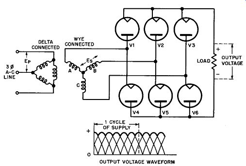
The full-wave delta-wye (sometimes called the three-phase, full wave bridge circuit) rectifier circuit shown in Fig. 20 is essentially an extension of the single-phase full-wave bridge rectifier, described in the last section (Fig. 10). Although this circuit uses double the number of tubes of the three-phase, half-wave, delta-wye rectifier (Fig. 16), it has the advantage of delivering twice the output voltage of the half-wave rectifier for the same total secondary voltage (E.). Note in Fig. 20 that each leg of the secondary wye is connected to the junction of two half-wave rectifiers, arranged back-to-back, so that full-wave rectification of both AC half-cycles is obtained from each phase. The waveform of the output voltage, shown at right in Fig. 20, is essentially the same as that of the double-wye circuit (Fig. 18), where the ripple-frequency of the output is six times that of the three-phase AC supply.

Fig. 20. Three-phase full-wave delta-wye rectifier and output waveform.
No balance coil is required, but the power transformer must have three secondary windings and the filament transformer must have four separate secondary windings, one for V1, V2, and V3, and one each for V4, V5, and V6. Since the rectified tube currents flow in opposing directions through the secondaries, no DC magnetization can take place. Three single-phase transformers may be used in place of one three-phase transformer.
As in the delta-star circuit, the average DC load current is 0.955 times the peak current through each tube, but one-third of the DC load current flows through each tube (rather than one-sixth, as in the delta-star circuit), because two tubes are required for each output current pulse. As pointed out before, the average DC output voltage is twice that of the three-phase half-wave rectifier, or 2 x 1.17=2.34 times the rms value of the AC voltage across each secondary leg. Conversely, the rms voltage across each leg need be only 1/2.34 or 0.428 times the value of the average desired DC output voltage.
Example: The transformer secondary voltage per leg (E,) in a full-wave delta wye rectifier is 150 volts rms, the load current 2 amperes. What is the average DC output voltage, the peak and average current through each tube, and the average power delivered to the load? Solution: Since the average DC output voltage is 2.34 times the rms voltage across each leg, the output voltage is 2.34 x 150=351 volts. The peak current through each tube is 1/0.955 or 1.05 times the average load current; the peak current is 1.05 x 2=2.10 amperes per tube. The average current per tube is one-third of the total, or 1 /3 x 2=0.667 ampere. Finally, the average power is the product of the average current and the output voltage, or 2 x 351=702 watts.
24. Uses of Polyphase Circuits
Polyphase rectifiers are used only when the efficiency of rectification is more important than the cost of the rectifier itself. This is generally the case when the required DC power exceeds about 1 kilowatt. Many industrial plants, broadcast and television stations requiring up to 20,000 volts DC at peak currents of 10 amperes or more utilize polyphase circuits. The tubes employed are generally the gas-filled (mercury-vapor) type. Polyphase circuits also have the advantage over single-phase types of developing fairly steady output voltages that require little filtering. Finally, the more efficient polyphase circuits give a higher output voltage relative to the peak inverse voltage of the tube and utilize the power transformer more efficiently than do equivalent single-phase circuits.
25. Review Questions
(1) State some of the advantages of three-phase power systems over single phase supplies.
(2) Draw the circuit and output waveform of a three-phase half-wave delta-wye rectifier and explain its operation.
(3) What is the advantage of the delta-zig-zag connection over the delta wye circuit? Is there any difference in the output waveform of the circuit; in the average and peak currents; in the ripple frequency?
(4) Why is the half-wave double-wye circuit sometimes called a six-phase rectifier? What is the ripple frequency of the output?
(5) Explain the function of the interphase balance coil in the double-wye circuit and how it affects the ratio of the peak current per tube to the average load current. Compare ratio with that of the half-wave delta-wye rectifier.
(6) Compare the operation of a double-wye circuit with that of the delta-star rectifier connection. How would you convert one into the other?
(7) A broadcast station requires a DC voltage of 2000 volts at a load current of 10 amperes. For both the delta-star rectifier (Fig. 19) and the double-wye circuit (Fig. 18) compute the required rms voltage across each secondary winding of the transformer, the peak and average current per tube, the DC power delivered to the load and the ripple frequency. (Neglect the tube and transformer voltage drops.) Which circuit would you choose?
(8) Draw the circuit of a three-phase full-wave delta-wye rectifier and compare its operation with that of a single-phase, full-wave bridge rectifier.
Compute the same data as for the review question (7) and compare all three circuits. If you had three single-phase transformers of the proper ratings available, would you change your selection in question (7)?
(9) Remembering the delta connection, draw the circuit of a three-phase full-wave delta-delta rectifier.