Thousands of watts of radio-wave power, transmitted from a tv or other transmitting antenna, are radiated outward. By the time they get to your receiving antenna very little is left. For the mathematically minded, the loss of power is the same as for light-the inverse-square law applies. That is, the loss is in inverse proportion to the square of the distance ( Fig. 2-1). The light passing through a 1-sq ft window at a distance of one foot would cover a 4-sq ft area at two feet. The intensity of the light at a single point at a distance of two feet is one fourth that at one foot. This is the inverse-square law, and it applies as well to the decrease in power of a radio wave as it travels away from a transmitter. The amount of power your tv antenna actually feeds to your set may be on the order of two or three hundred microwatts (millionths of a watt). It is for this reason that it is important to use a highly efficient antenna, especially if there is any appreciable distance between the transmitter and the receiver.
RESONANT ANTENNAS
You have probably smiled at the feat of a singer breaking a glass when he hits a certain note. The dimensions of fine glass can be such that when the glass is subjected to vibrations of a certain frequency they will cause stresses in the glass, and it will shatter. Piano strings are different in length, and when struck by the hammer will vibrate at specific musical frequencies. The longer strings ( or wires) vibrate at low frequencies and the shorter ones at higher frequencies. These are examples of "resonance." The structure and size of the glass and the length and tautness of the piano strings determine their resonant frequency, or frequency of natural vibration. This is mechanical resonance.
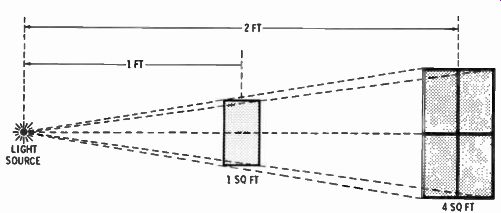
Fig. 2-1. The inverse-square law.
When a length of wire is cut to a specific size, it becomes electrically resonant to radio waves of a specific frequency (Fig. 2-2). When an antenna is resonant, it will do a much better job of converting the feeble radio waves to power that can be used by the receiver. The transmitting antenna is al ways built to resonate at the transmitting frequency; so are receiving antennas for communication purposes, such as CB antennas. The longer the main element of the antenna, the lower the resonant frequency, as in the case of the piano strings.
RESONANT LENGTH EQUALS 1/2 WAVELENGTH )) FEED LINE
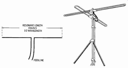
Fig. 2-2. Half- wave dipole. Fig. 2-3. Poly-directional fm antenna.
In the early days of tv when there were fewer choices of channels on the air, tv receiving antennas were actually made resonant, and some masts and towers had two or three antennas on them, each dimensioned for a specific tv channel.
Television sets were not nearly as sensitive in those days, and every bit of power from the antenna had to be conserved. A current example of a resonant antenna is the Archer fm antenna in Fig. 2-3. It uses two resonant dipoles on one mast, perpendicular to each other, for poly-directional characteristics.
Transmitters and receivers contain resonant circuits within them. When you switch channels in a tv set, you are switching to different resonant circuits. This not only makes the set selective to only the one channel, but increases the sensitivity to that channel. The resonant circuits are in the form of small coils and capacitors, and are called "lumped" resonant circuits, instead of a piece of stretched out aluminum tubing.
But how does a single antenna respond to a number of tv channels, covering the frequency range from 54 MHz to 890 MHz?
BROADBAND ANTENNAS
To overcome the need for multiple antennas for tv reception, a single antenna with multiple elements is used to cover all the channels. While this represents a compromise over the use of a single resonant antenna, modern engineering has developed today's tv antenna to a remarkable degree of efficiency.
Look at a modern tv antenna ( Fig. 2-4) and notice the two rows of elements. The two rows are for each half of the vhf Channels, 2 to 6, and 7 to 13. The frequency assignments are not continuous; there is a gap between Channels 6 and 7. In each row the elements are graduated in length, the shortest elements being approximately resonant to the highest frequency or highest channel, and the longest to the lowest channel. The design is such as to give overlapping frequency coverage to all channels.
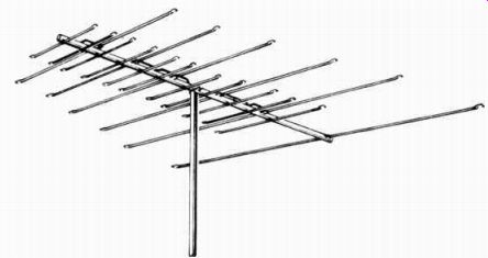
Fig. 2-4. Modern tv antenna.
There is further value to this type of construction. Each longer element acts like a reflector to the element in front of it.
In this way, some of radio wave energy getting past an element is reflected back to the shorter element in front, for increased signal strength. So, not only is a modern tv antenna broadband in its ability to pick up all channels, but it has directional qualities. Its pickup is greater from in front than from the rear or sides. This directional effect is very important in the reduction of images, as mentioned in Section 1.
There is a limit to the broadband reception capabilities of a tv antenna. There are two frequency ranges, Channels 2 to 13, covering from 54 MHz to 216 MHz, and Channels 14 to 83, covering from 470 MHz to 890 MHz. The latter range is called uhf, and is widely separated from the vhf range of Channels 2 to 13. Look closely at a modern vhf/uhf tv antenna ( Fig. 2-5) and you will see a number of longer elements and a separate group of much shorter ones. The longer elements are for the vhf range, and the shorter elements are for the uhf range.
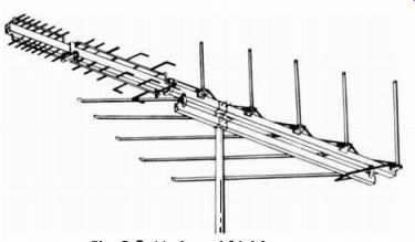
Fig. 2- 5. Modern uhf/vhf tv antenna.
What we have, therefore, are two tv antennas in one. The design is such that a single lead-in serves both parts of the antenna.
ANTENNA LEAD-IN
The quality and type of lead-in from the antenna to a tv set is important in critical installations. That is, for best reception of color where the tv station is at some distance from your lo cation, or where the lead-in must be extra long because of the position of the antenna, lead-in quality becomes important.
There are basically two types of lead-ins ( Fig. 2-6). The most popular consists of two parallel wires separated by an insulation material. This is called twin lead, or 300-ohm twin lead. It consists of two wires; each wire has several small-sized wires twisted together to form one larger size. The insulation which holds the wires parallel is flexible polyethylene. The other type of lead-in is coaxial cable. It has a single central wire, either solid or stranded, surrounded by a polyethylene insulation, which in turn is surrounded by a braided outer wire shield. This shield is in turn covered with a polyethylene outer jacket. Coaxial cables come in various sizes and types and are designated by a code beginning with the letters RG, followed by a number. The one used mostly for tv antennas is RG-59/U. One advantage of coaxial cable is its shielding effect due to the outer braid. Being round, also, the cable is more easily run from one point to another. However, its principal feature is in the shielding. It is not too important that the cable be kept from sources of possible noises such as lines feeding a universal or brush-type motor, or belt-driven motors in which static noises can be developed by the belt, or near ac lines connected to thermostatic switches.
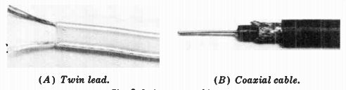
(A) Twin lead. (B) Coaxial cable.
Fig. 2-6. Antenna cable.
The quality of tv lead-in wires has to do with the quality of the polyethylene insulation. The better quality is thicker and of purer material. The clearer the color ( a milky white) the better the quality. Polyethylene has a tendency to deteriorate with time. It is important to purchase good new stock, and to replace the cable every few years, as determined by a changing picture quality. Superior twin lead has a foam polyethylene insulation. Its web-like structure contains tiny air pockets which improve on the insulation qualities and a dense, outer jacket to reduce the penetration of ultraviolet rays. This Radio Shack cable carries a life guarantee of 20 years.
A shielded 300-ohm twin lead is also available. This provides the shielding against pickup of electrical noises and isolation from effects of nearby metal objects, without changing to the 75-ohm coaxial cable.
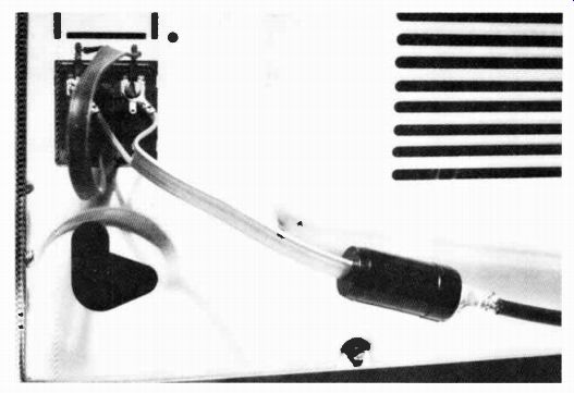
Fig. 2-7. Impedance- matching transformer.
IMPEDANCE MATCHING
Don't let this term stop you, as we will not dwell on it long.
If you are a hi-fi bug you know that speakers have an impedance of 8 ohms, or 16 ohms. But the output stage of the amplifier, whether transistorized or vacuum tubes, produces its greatest undistorted output power when it drives a certain impedance, usually much higher in value than 8 or 16 ohms. A transformer in the amplifier changes one impedance to the other. The point is the amplifier must "see" the proper impedance for maximum power. The amplifier is the "source" and the speaker or speakers are the "load." The same is true in a tv set. The lead-in is the "source" and the tv set is the "load." Most tv sets are designed to have a 300-ohm input impedance.
Therefore, the 300-ohm twin lead mentioned earlier does match the set. Some color tv sets are designed for 75 ohms input, and coaxial cable is the correct match. Most modern day color tv sets have a 300-ohm input, so a transformer is used to change the 75-ohm impedance of coaxial cable to 300 ohms, if coaxial cable is used ( Fig. 2-7).
Another point where impedance matching is important is between the antenna and lead-in. Most tv antennas are designed to match the usual 300-ohm twin lead. A few antennas are de signed for matching directly to 75-ohm coaxial cable. Where they are not matched, a transformer at the antenna can provide that match.
There is another reason why it is important to match impedances for tv. Lead-ins are of a certain length, and they are also resonant to a certain frequency, depending on that length.
A resonant lead-in can set up ghosts on the picture. In the case of color, color fringes can develop from a resonant lead-in.
However, when the impedance is matched, the lead-in is non resonant.
Impedance matching, therefore, is important to save every bit of that feeble tv signal and get it to the tv set, and to re duce the possibility of producing additional ghosts from the lead-in.
DIFFERENCE BETWEEN TV, FM, AND CB ANTENNAS
The difference between these basic types is one essentially of decreasing frequency coverage from a single antenna. Here it is in a nutshell.
TV Antenna. Two groups of increasing size elements for covering the range from 54 MHz to 216 MHz, and from 470 MHz to 890 MHz. Each larger element size acts like a reflector to the one in front of it, giving the antenna a unidirectional reception pattern.
FM Antenna. The simplest type is a single element, folded over and called a folded dipole. This single dipole is capable of covering the limited frequency range from 88 MHz to 108 MHz. Because fm stations may be in different directions from your location, a common type is a dual dipole to give poly-directional pattern reception ( Fig. 2-3).
CB Antenna. A quite sharply resonant antenna, as it needs only to cover a range from 26.965 MHz to 27.255 MHz of the 11-meter CB band. Most CB antennas are a single element in a vertical position, called a quarter-wave vertical. Some CB buffs who want to increase the effective radiated power will resort to a beam-type antenna very much like radio amateurs do. These are mounted on a rotator for changing direction.
The quarter-wave vertical is easy to mount onto a car for mobile operation. The last three sections of this guide cover the subject of CB antennas.
Next: TV ANTENNAS
Prev: RADIO WAVES
AMAZON multi-meters discounts
AMAZON oscilloscope discounts
Also see:
Industrial Electronics (in the early 1960s)
199 Electronic Test & Alignment Techniques (1972)