As indicated in Section 2, tv antennas must be designed to receive a very wide band of frequencies for the many tv channels, and receive them with highest possible efficiency. The antenna engineers must be honored for developing today's de sign which makes possible such wide-band coverage, along with high unidirectional characteristics and high sensitivity.
To see the engineering behind an antenna, let us look briefly once again at the tv channel frequencies.
VHF AND UHF TV CHANNELS
Fig. 3-1 is a chart of the radio frequencies between the be beginning of the broadcast band and the tv frequencies. The scale is logarithmic or the chart would run way off the page.
The spaces between the broadcast band and the beginning of the tv channels are occupied by commercial stations, foreign broadcasts, amateur activities, government and military frequency assignments, etc. Note the gap between Channels 6 and 7. The section between Channels 2 and 6 is called the low-vhf band, and the section between Channels 7 and 13 is the high-vhf band. Although we talk about Channels 2 through 13 being the vhf tv band, as though it were a continuous band, you can see that it is not.
The frequency of each channel in the high-vhf band happens to be about three times the frequency of those in the low-vhf band. ( See the table in Section 1.) This is fortunate to some tv antenna design. The lengths of the elements used in the low-vhf band, each about one-half wavelength in length, be come three half-wave dipoles to the high-vhf band. Therefore,...
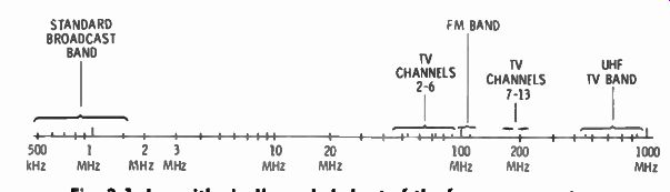
Fig. 3-1. Logarithmically scaled chart of the frequency spectrum.
...the same elements can, with performance compromise, serve both sections of the vhf band.
Archer antennas do not compromise the performance of the higher-vhf band but, instead, add the shorter elements as di poles for this section. This is easily seen in Fig. 3-2. While the ...
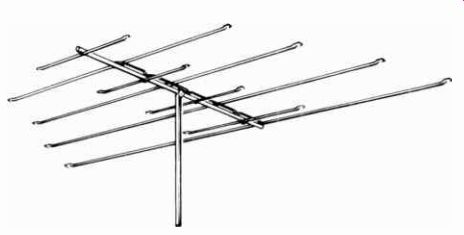
Fig. 3-2. Eight- element vhf tv antenna.
... shorter elements appear to be about one-third the length of the longer elements, they are truly half-wave dipoles in the channels from 7 to 13.
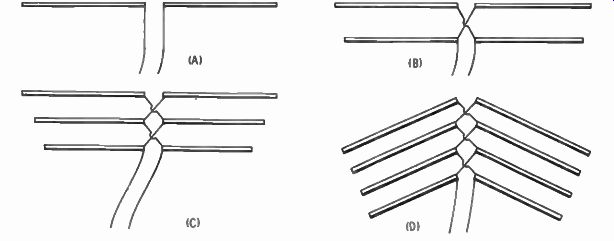
Fig. 3-3. Evolution of a four-element vhf antenna.
The four diagrams in Fig. 3-3 carry us through the evolution of a four-element vhf antenna. For the sake of clarity only the low-frequency section is shown. Diagram A shows a single element called the half-wave dipole. In diagram B another element is added, but at a longer length. This second element resonates at a lower channel and also acts as a director for the shorter element. In diagram C a still longer element is added for a still lower channel (or lower frequency), and it becomes a reflector for the shorter element in front of it. In diagram D a fourth and still longer element is added. It becomes a reflector to the shorter element, as well as resonating near the low-frequency end of the low-section vhf band, or near Channel 2. To aid in the directivity of this antenna, the elements are bent forward.
The above illustration shows each element connected to the lead-in, in a system called cross-phasing. In some antenna de signs, director and reflector elements are added but not connected to the lead-in.
The fm band at 88 to 108 MHz is just above tv Channel 6 in frequency. The broad tv antenna coverage includes the fm band. A tv antenna will also operate an fm tuner or receiver, and it is common practice to take a tap off the lead-in to serve both a tv set and fm tuner or receiver.
The uhf bands are considerably higher in frequency than the vhf bands. While the frequency range is not broken up into sections as with the vhf band, they are divided into two parts for two types of service. Channels 14 to 70 ( about 470 MHz to 812 MHz) are for regular tv broadcasts. Channels 71 to 83 (about 812 MHz to 890 MHz) are for translator service. Translators are located in smaller communities and act as relays for programs originating in a nearby metropolitan city. They are automatic in operation; that is, they are unmanned. Thus, com munities too far from regular tv stations have tv service.
Very large cities with more tv stations than can fit in the vhf bands will also have uhf tv stations. These operate in Channels 14 to 70. It is obvious the antenna described earlier in this section would operate poorly in the uhf band. The elements are much too long to be resonant to the much higher uhf frequencies.
Coverage of the uhf band is accomplished by adding a separate section to the same boom.
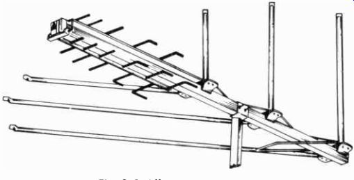
Fig. 3-4. All-coverage antenna.
Fig. 3-4 is an example of an all-coverage antenna, one that receives vhf, fm, and uhf with high efficiency. Note the odd looking front part of the antenna. This part has the short elements needed to resonate at the uhf frequencies. The engineering behind it is generally the same as for the vhf part of the antenna. Usually more elements are used, because the overall ...

Fig. 3-5. Uhf antenna. Fig. 3-6. Corner- reflector uhf antenna.
... frequency coverage is greater and more sensitivity is needed to overcome the greater losses encountered at such high frequencies.
Losses are somewhat greater at uhf frequencies than at vhf frequencies, both in the transmission and the reception. Hills, trees, terrain, and other obstructions affect the transmission more at uhf than at vhf frequencies. Television set sensitivity is less at uhf. Losses are greater in the lead-in. This is why distance specifications on tv antennas are less for uhf than for vhf.
Where uhf translator tv service only is available, it is un economical and unnecessary to invest in a full-coverage vhf-uhf antenna. Television antennas and equipment for the reception of the uhf channels are available.
The uhf end of the antenna illustrated in Fig. 3-4 can be purchased separately. This is shown in Fig. 3-5. The elements are graduated in size and follow the same general engineering concept as antennas for vhf. This is the lowest priced of the Archer uhf tv antennas and has excellent sensitivity and directivity. Fig. 3-6 shows a corner-reflector uhf tv antenna. It consists of a single dipole in the locus of an array of elements ...
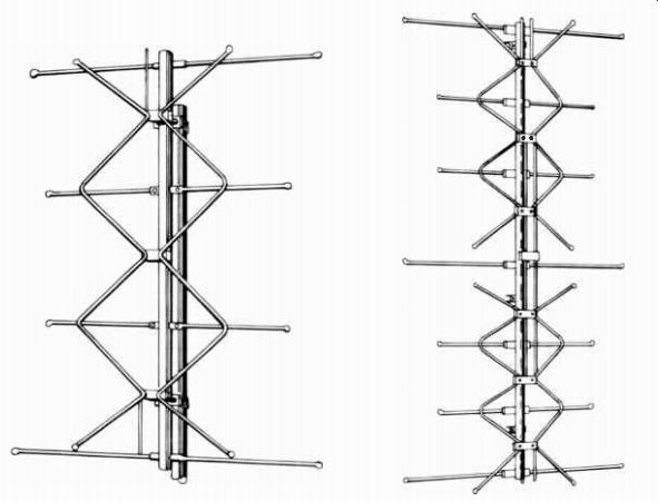
Fig. 3-7. " Bow-tic" uhf
antenna with four bays.
Fig. 3-8. " Bow- tie" uhf antenna with eight bays.
... shaped like a large reflector screen. It has high gathering power. Some of the radio waves that might otherwise go past the dipole, above it, or below it are reflected down or up to it.
The four-bay uhf antenna of Fig. 3-7 has even greater "capture power" because of its size. (The vertical boom is 30 inches high.) This type of antenna is essentially poly-directional and is excellent in areas where several translators may be located on separate hills or buildings. Fig. 3-8 shows the same antenna but in an eight-bay configuration with an obvious improvement in gain.
COLOR TV ANTENNAS
In addition to a very wide bandwidth, each individual tv channel covers a rather wide frequency range, as compared to voice communication transmitters, for example. A minimum bandwidth of 4.5 MHz is covered by one tv station. The selectivity of a black and white set just covers that minimum of 4.5 MHz, dropping in sensitivity rather rapidly at the two extremes. A color tv set, however, must have a wider band width, and 6 MHz is about their standard. This is to assure good reception of the added color information on the signal.
For those who understand it, the response curve difference between a black and white set and color set is shown in Fig. 3-9.
The explanation of it is too technical to go into in this guide. The point is, the color information transmitted is in addition to the black and white information, and unless the set can pick up the color information, true colors on the picture tube will not be realized.
Antenna response to color tv signals must be flatter across each channel, in addition to covering the entire bandwidth.
That is, the antenna must respond equally to all frequencies on each channel. This makes engineering requirements much tougher, but with the greatly increased use of color sets, nearly all well-engineered antennas are designed for good color reception. This is true of the entire Archer line of outdoor tv antennas. Fig. 3-10 illustrates the top of the Archer line, recommended for deep fringe reception or where high directivity is important. At the other end, even the one shown in Fig. 3-4, selling for less than $16.00, is designed for color tv reception on all tv bands and fm.
PICTURE SOUND FREQUENCY
FREQUENCY (A) Black and white tv Bete.
(B) Color tv sets. 1.25MHz 3.8 MHz CHROMINANCE SUBCARRIER
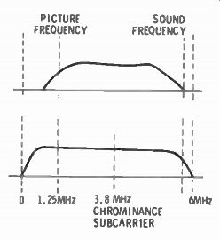
Fig. 3-9. Frequency-
response curves. 6MHz
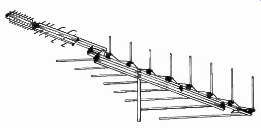
Fig. 3-10. Deep fringe tv antenna.
A stronger signal must be fed into the tv set input for color than for black and white. A weak signal on a black and white set will result in some "snow." If you live some distance from a tv station, you may be tolerating the snow. If now you are contemplating the purchase of a color tv set, you must consider improving the antenna system. If you attempt to operate the color set from the same antenna, you will surely suffer in color quality. The 3.58 MHz subcarrier also transmitted with the picture carrier and sound carrier on each channel carries the modulation for color information. Without a strong 3.58 MHz signal, the color information will be lacking and color will be degraded.
An earlier section described how ghosts were developed on a picture tube. As with snow, a faint ghost on a black and white set is often tolerated. In a color set it cannot be, as too often the ghosts are of differing color and most annoying. Thus, the antenna must have high unidirectional qualities, to eliminate the secondary transmission path and correct impedance matching to keep the lead-in a nonresonant line.
Fig. 3-11 illustrates a good choice of a tv antenna for moderate distances at reasonable cost, yet with a sharp front lobe in its pickup pattern.
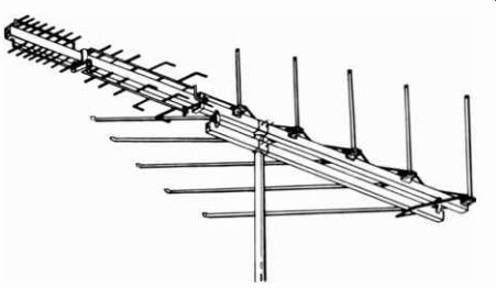
Fig. 3-11.
Moderate distance all-coverage tv antenna.
ANTENNA ELEMENTS VERSUS DISTANCE
Most catalogs describing tv antennas show the distance over which they will receive good pictures on the vhf bands. With an increase in the number of elements used in the antenna, there is an increase in its ability to reach out for good reception.
Another method of indicating the sensitivity of an antenna is the area over which one may expect good performance. This may be shown as metro, suburban, medium, fringe, or deep fringe. The words are almost self-explanatory. Metro means metropolitan, or within a city. Suburban means the suburban towns around the metropolitan area, etc.
Because of decreased efficiency in the uhf band, the distance indicated for uhf is usually about 25% less. This varies de pending on the type of uhf section added to the antenna.
Keep in mind that the number of elements mentioned for an antenna includes the elements of the uhf section on vhf/fm/uhf antennas. A vhf/fm antenna for the vhf bands ( always including the fm band) may only list a greater distance for a fewer number of elements.
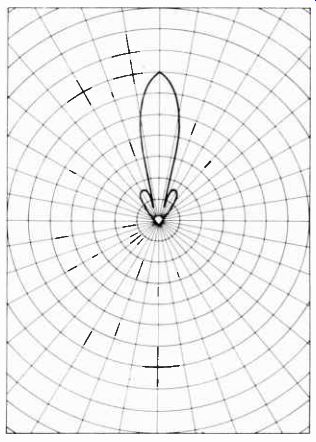
Fig. 3-12. Polar pattern.
The greater distance ability of an antenna is not so much a function of the number of elements directly, but is due to the fact that more elements increase the forward lobe of the polar pattern ( Fig. 3-12). With more elements the unidirectional characteristics are improved. By reducing the pickup from the rear and sides, the antenna has better sensitivity to signals from the forward direction.
WHAT ANTENNA TO BUY
Before you buy a tv antenna, you should ask yourself a number of questions.
1. Are the tv stations in your area on the vhf bands only, the uhf band only, or do you have both?
2. How far from the stations' transmitting towers are you?
3. Are the towers in "line-of-sight" or are there buildings, heavy tree growth, hills, or other obstructions in the way?
4. Are you operating a black and white set, or a color tv set?
5. How many tv sets will the same antenna be expected to serve, and is an fm tuner or receiver to be on the line?
If you have both vhf and uhf tv service in your area, then the antenna to purchase is one of the Archer "Color Supreme" series. Among the six models in this line will be one that will also answer the other four questions. The Archer "Color Eagle" series is for vhf and fm only and will provide outstanding results at these lower frequencies. The five models in this series provide a wide choice for the other considerations. There is no need to spend the money for the added uhf section of an antenna, unless uhf service is in your area or is anticipated at an early date. For uhf reception only, or where uhf translators are the only tv service in your community, four models are available.
As explained before, the number of elements in an antenna is related to its distance-getting ability. Here again, however, the answer as to choice is related to the answers to the other questions listed above. The greater the number of elements in an antenna, the greater the distance over which it will bring in good signals. An example of a good choice of an antenna for use in the suburbs of a large city, in which the tv towers are all in the center of the city on a high building, and both vhf and uhf service is provided is pictured in Fig. 3-13. If your suburb is well within the mileage limit for this antenna ( 90 miles vhf, 60 miles uhf, 60 miles fm), as you almost surely are, you can count on this antenna having the extra directional qualities to eliminate or reduce ghosts, or overcome obstructions, or operate more than one set.
The third question is almost answered in the previous statements. It is hard to determine to what extent there are obstructions in the path of the signal if you cannot see the transmitter tower from the roof of your house. A good check on your antenna need is to talk with a few neighbors. Note the results they get, and the number of elements in the antenna they are using.
A building or a stand of trees in the way are not total obstructions. The tv signal does bend around obstructions and to some extent go through them. But when it does, there is a loss of signal strength.
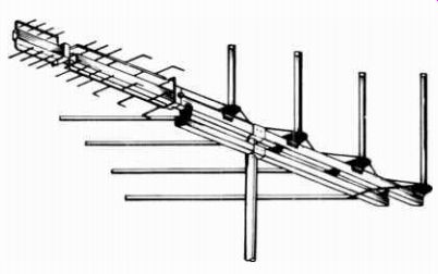
Fig. 3-13. Suburban antenna.
For reasons mentioned earlier in this section, the reception of a good signal for color is more important than for black and white. Also, remembering what was said about the need for wide frequency response, it is obvious that the distance from the transmitter is not the paramount consideration in the purchase of a tv antenna for color reception. The investment made in a color set is considerably more than in a black and white set. The investment in an antenna for the set should be in pro portion. As a rule of thumb, select an antenna one step up from one that might have been selected for a black and white set.
If you live in the metropolitan area, select a suburban antenna.
If you live in the suburbs, you should select a medium range antenna, etc.
If you operate more than one set from a single antenna, the low signal power brought to the end of the lead-in will be divided among the number of sets to be connected. Here again, a good rule of thumb is similar to the one mentioned above. If you operate two sets from one antenna, select the next better antenna than the one that would be indicated for your area.
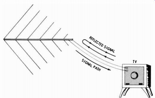
Fig. 3-14. Reflected waves causing color fringing.
Remember to use couplers-two-set or four-set-to maintain a proper impedance match. Without the use of the couplers, there s no impedance match, which will result in a further decrease in the signal reaching each set.
Other considerations in the selection of a tv antenna are mechanical as well as electrical. Archer tv antennas are sup plied preassembled; elements snap into position easily. All are finished in gold vinyl, acrylic, or other weather-resistant material. Installation is easy.
IMPORTANCE OF LEAD-IN
Impedance matching is important, especially for good color.
There must be a correct impedance match between the antenna and the lead-in, and between the lead-in and the tv set. If not matched, the lead-in will set up reflected waves which will result in color fringing.
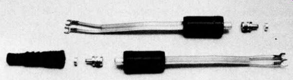
Fig. 3-15. Impedance-matching
transformers.
The reflected waves result in delayed signals built up in the lead-in. As shown in Fig. 3-14, some of the signal reaching the tv set is reflected back up the lead-in to the antenna, then reflected back down again. The effect is similar to a secondary signal path bounced off a nearby hill or other large object, except that the delay in the lead-in is much shorter. The result is color fringing, rather than an actual visible ghost image on the screen. Under matched conditions there are no reflected waves, therefore no secondary delayed signals and no color fringing.
A good lead-in cable for color is coaxial cable. An installation would include a transformer at the antenna ( Fig. 3-15) to change the 300-ohm impedance of the antenna to the 75-ohm impedance of the coaxial cable, and another transformer at the input terminals of the tv set to change the 75-ohm impedance of the coaxial cable back to the 300-ohm impedance of the set.
Of course, 300-ohm twin lead could be used for the lead-in, and no transformers would be needed and everything would be matched. But unshielded twin lead, unless very carefully placed, can be troublesome. Lacking a shield it can pick up unwanted noises from nearby sparking or static-producing equipment.
Should it come close to other metal, such as a metal gutter at the edge of the house, the capacitive effect of the gutter or other metal object can upset its impedance.
There is a shielded 300-ohm twin-lead cable, made especially for color- tv installations. A Mylar-backed aluminum foil is wrapped over the outside for shielding. The shield is covered by a polyethylene jacket. This cable eliminates the precautions required for carefully placing ordinary twin lead, and also avoids the need of installing transformers at the antenna and the tv set for an impedance change.
ROTATORS AND THEIR IMPORTANCE
As a general rule all tv station antennas are located in one place; either on a tall building in the center of the city, or on top of a high hill or mountain. But this is not always the case.
A few places do not combine all tv service in one place. Further more, if you live out in the country and are in a position to receive tv service from two or more cities, your tv watching pleasures could be limited if you did not have a method of changing the direction of your antenna.
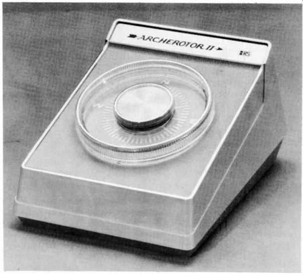
Fig. 3-16. Automatic rotator.
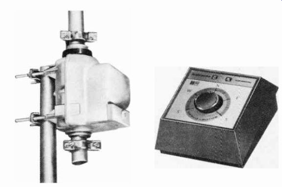
Fig. 3-17. Deluxe automatic rotator.
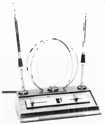
Fig. 3-18. Indoor tv antenna.
A central point of transmission is often not the case for fm.
Too often, a central high point of transmission for fm entails an expense not compatible with the smaller fm audience com pared with tv. If good stereo fm reception is important from the tv antenna, investing in a rotator may be worthwhile. In this way you can swing the antenna around towards the desired fm transmission. This can make the difference between receiving fm with ideal hi-fi conditions, or lower fidelity, especially with stereo.
Television ghosts in the picture result from a second path of transmission from a nearby hill, building, tower, or other object. The effect may vary from tv channel to channel. One method of overcoming ghosts on tv sets is to mount your tv antenna on a rotator. This allows you to adjust the direction of the antenna for minimum ghost effect. It is sometimes desirable to point the antenna slightly away from the primary tv transmission. While there may be a slight loss in primary signal strength, there could be a much greater loss of the signal from the secondary path, with an overall improvement of picture. Figs. 3-16 and 3-17 show two models of Archer rotators.
Setting the dial to the direction starts the motor turning, stop ping automatically at the desired point,
INDOOR ANTENNAS
Under some conditions an indoor antenna will give remark ably good results. In a small city, consisting primarily of homes, obstructions in the path of the signal can be at a minimum and an indoor antenna will operate quite well. The better indoor antennas are adjustable as to signal frequency and impedance match ( Fig. 3-18) . A complete section is devoted to this subject later on.
Next: SPECIAL ANTENNAS FOR FM
Prev: Link | --WHAT ANTENNAS DO
AMAZON multi-meters discounts
AMAZON oscilloscope discounts
Also see:
Industrial Electronics (in the early 1960s)
199 Electronic Test & Alignment Techniques (1972)