More and more homes now have two or more sets. Two-set homes may nearly equal, if they do not already exceed, the number of homes with one tv set. Also, operating an fm tuner or receiver off the same antenna with a tv set is quite popular.
Assuming a reasonably good antenna and a reasonable distance from the tv station, along with the high sensitivity of the modern tv set, there is no reason why more than one set cannot be operated from a single antenna. In doing so, however, it is advisable to observe certain rules for best results, especially if a color set is one of those on the same line.
IMPEDANCE MATCHING
Only when a lead-in is terminated with a load in its characteristic impedance is the lead-in nonresonant. This may sound a bit complicated, but it only means that a 300-ohm twin line should be connected to a 300-ohm load. When the end of a 300 ohm lead-in is connected directly to the antenna terminals on the back of a single tv set, the set is the 300-ohm load, and the impedance is matched. If two sets are parallel-connected ( Fig. 6-1) to the single lead-in, the lead-in "sees" a different impedance. The equivalent impedance will be 150 ohms. This is shown schematically in Fig. 6-2. The point is, two things hap pen when the lead-in impedance is mismatched: the wires of the lead-in could become resonant at certain frequencies, and produce color fringes in the picture of a color-tv set; signal losses are increased and some of the signal from the antenna is wasted.
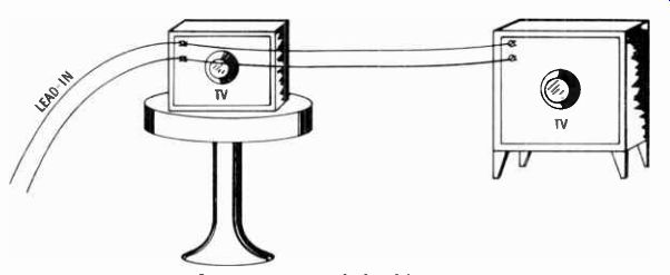
Fig. 6-1. Connecting a single lead-in to two tv sets.
Impedance matching is achieved with the use of trans formers. These work like the transformers in the output stage of a hi-fi amplifier, as described in Section 2. Special coils change one impedance value to another at minimum loss.
Two types of impedance-matching couplers are generally available. Fig. 6-3 shows a two-set coupler. It has three sets of ...
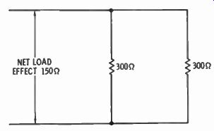
Fig. 6-2. Schematic of
Fig. 6-1. NET LOAD EFFECT 150 ohm ; 300 ohm; 300 ohm
...screw terminals. One set is for connecting the lead-in. The other two are for the two sets. The same kind of 300-ohm lead-in wire may be run from the coupler to the tv sets. This is the way it is usually done, with the coupler located somewhere convenient to both sets. Fig. 6-4 shows a four-set coupler. The five sets of terminals are for the lead-in, and for the wires to the four sets.
It should be located where distribution cable to each set can be kept to a minimum length.
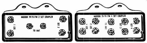
Fig. 6-3. Two-set tv coupler. Fig. 6-4. Four-set tv coupler.
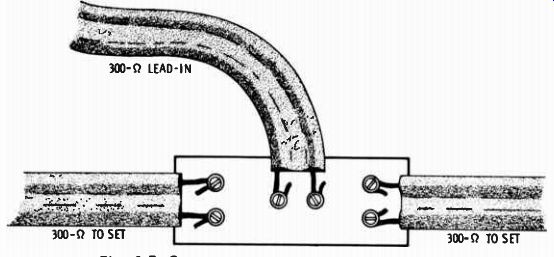
Fig. 6-5. Connecting two tv sets to one antenna.
What do you do when you want to connect to only three tv sets, or two tv sets and an fm tuner? Use a four-set coupler.
However, it is best to connect a "dummy load" to the fourth terminal set. All this means is to connect a 300-ohm resistor to the terminals. While this results in a waste of some of the power, it does maintain the impedance match. A 1 / 2 - watt, 300 ohm carbon resistor can be purchased from a local electronic parts supplier for only about 10 or 12 cents.
Fig. 6-5 shows how to connect a two-set coupler. The coupler itself should be located at a point where it results in a minimum overall amount of cable run. If in-the-wall lead-in installation is used, a good place for the coupler is in the attic. The same hookup is used for one tv set and an fm tuner, merely substituting the tuner for one tv set.
Fig. 6-6 shows the hookup for a four-set coupler. In this dia gram three tv sets and an fm tuner are connected to the coupler, and all are operated from a single antenna. Fig. 6-7 shows what a resistor looks like. To substitute the resistor for a tv set, merely bend the two leads of the resistor, twist one lead around each of the screw terminals of the unused set ( Fig. 6-8), and tighten the screws.
TO FM TUNER
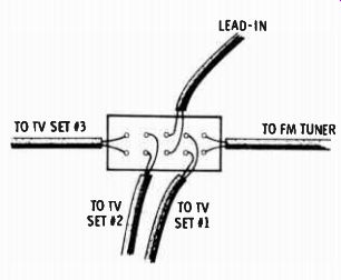
Fig. 6-6. Connecting three tv sets and on fm tuner to one antenna.
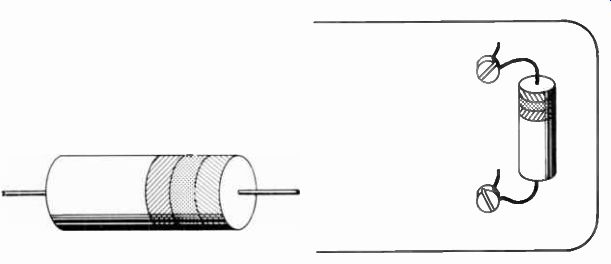
Fig. 6-7. A typical carbon composition resistor.
Fig. 6-8. Installing a resistor onto a coupler.
Sometimes conditions are such that it is more convenient to place the coupler outdoors and run separate lead-in wires into the house to the individual sets. Fig. 6-9 shows a two-set splitter/coupler, but in a weatherproof housing, and with clamps for fastening it to the mast holding the antenna. A mast mounted, four-set coupler is also available.
Similar couplers are available for use with 75-ohm coaxial cable. The difference is only in the method of termination on the boxes. Small coaxial cable jacks are used instead of screw terminals. The cables must have mating plugs connected to their ends. Also, each tv set must have a transformer on the back, at the terminals, to change 75 ohms to the 300-ohm in put impedance of the tv set.
In small apartment buildings, up to eight sets may be fed with the same antenna. One two-set and two four-set couplers can be connected into a distribution system as shown in Fig. 6-
10. Since you will be dividing the available power by eight, a good antenna must be put up and installed as high above the roof as practical.
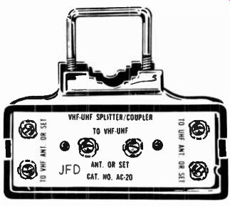
Fig. 6-9. Two-set splitter/coupler.
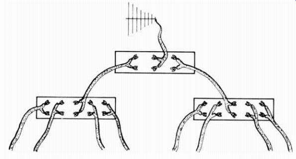
Fig. 6-10. Two-set coupler feeding into two four-set couplers.
AMPLIFIED SYSTEMS
In larger apartment buildings, and in hotels and motels, an amplified system is required. Specially designed amplifiers build up the signal from the antenna and make it possible to feed a very large number of sets. While the amplifiers are powered by the ac lines, they are designed to draw very little current from the line, and may run 24 hours a day at low cost. Thy are transistorized and may run for years without need for service.
Usual practice is to install an amplifier right at the antenna, between the antenna terminals and the lead-in. The lead-in carries the tv signal down and power from a small power sup ply up to the amplifier. Additional amplifiers are placed at distribution points, then cables are run from them to the tv sets.
These amplifiers also have built-in couplers. General practice is to use 75-ohm coaxial cable throughout the system, because of the ease of installation.
Amplified systems are a little beyond the capabilities of the average home mechanic. Their installation is best left to the professional organizations, who are better equipped with the necessary tools and knowledge.
INTERCONNECTING CABLE
Coaxial cable is round and small in diameter. Running the cable from antenna to coupler to sets poses no problems. However, it is expensive, and there is a need to install plugs onto the ends of the cables.
Three hundred-ohm twin lead distribution is less expensive than coaxial cable, and connecting them to couplers and tv sets is a simpler job. It is only necessary to strip a little insulation off the ends and wrap the wires around the screw terminals and tighten down on the screws. Some couplers even have claw like washers under the screw heads which bite down through the insulation and eliminate the job of stripping. This is not true at the tv set terminals, however.
The only precaution that must be observed in running twin lead cable around is to avoid coming near large amounts of metal. The cable should not be run near or parallel to electric wires, or water or gas pipes. There should be a distance of at least four inches from such metal. Shielded cable eliminates this precaution.
Running twin lead around the wall molding is fairly easy except when going from one room to another. Running it around door openings poses a problem and requires a little ingenuity. Special tacks are available to hold the cable in place against the floor molding. Since some 300-ohm cable is either white in color, or clear, there usually is no problem, of wall color matching.
The best way to feed cable to the sets is through the wall, and is fairly easy in a one-story home with an attic. The lead-in may be brought into the attic from the antenna either directly through the roof, or around over the edge of the roof overhang (or via the basement or crawl space) . The coupler is fastened to the top of a ceiling joist, or to a roof rafter. Or it may be just laid on top of a ceiling joist without fastening. Nothing will disturb it. The cables to the individual sets are dropped through a hole in the wall plate to a point in the wall near the set.
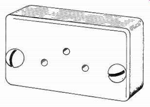
Fig. 6-11. Antenna outlet.
The inner walls of nearly all homes have 2 x 4 studs between the plaster boards. No insulation is used in the inner walls and, usually, there is no obstruction to dropping the cable to a point about a foot above the floor line. In some cities the fire codes require firebreaks ( fire stops) in walls. These are horizontal pieces of 2 x 4 studs about halfway up the wall. Going through these poses a problem. If your home has a basement or crawl space, coming in from below avoids the firebreak pieces.
The best way to do an in-the-wall installation is at the time the home is being build. Just before the plaster walls go up is an ideal time to get in and run the cable.
Fish the cable through a hole cut into the plaster near the tv set. A better way is to install a tv antenna outlet ( Fig. 6-11).
Next: HOW TO INSTALL A TV ANTENNA
Prev: Link | --FRINGE AREA TV/FM ANTENNAS
AMAZON multi-meters discounts
AMAZON oscilloscope discounts
Also see:
Industrial Electronics (in the early 1960s)
199 Electronic Test & Alignment Techniques (1972)