The word fringe means the outer area of good tv reception, beyond which enjoyable reception should not be expected. It may be defined as somewhere between 100 and 150 miles, the extremes of which might be named near fringe and deep fringe.
The words are rather nebulous and even the distances are not clear, as so much depends on factors and not just distance.
Conditions of terrain count as much as distance.
DISTANCE AND SIGNAL STRENGTH
In earlier sections we discussed the similarity between light and radio waves, and the loss of signal based on the inverse square law. Signal loss is related to the square of the distance.
At 50 miles a signal is only one-fourth as strong as at 25 miles.
At 100 miles it is only one-fourth as strong as at 50 miles. At 100 miles it is only one-sixteenth as strong as at 25 miles. The sketch of Fig. 5-1 is another method of showing this. To make an even more extreme comparison, city folks living at about 10 miles from a tv transmitter have no problem with tv reception on the basis of distance only. Their "country cousins" living 100 miles from the same transmitter are faced with receiving a signal only one-hundredth as strong, so they must take special steps to make the best of that weak signal.
The inverse-square law is based on free-space conditions; that is, with nothing else interfering. But at the surface of the earth other things do interfere-the horizon and hills or rolling terrain.
Light bends very slightly around the curvature of the earth.

Fig. 5-1. The inverse-square law.
The prism effect of the denser atmosphere near the surface and lighter atmosphere higher up is what puts a small bend in light. Radio waves will follow the curvature of the earth much more than light waves, for reasons other than the prism effect of the atmosphere. At low radio frequencies the bend is considerable. This is why you can pick up broadcast stations at night a thousand or more miles away from your car radio as you travel across country. ( Long distance transmission is better at night due to rearrangement of the ionized layers.) At higher radio frequencies, radio waves begin to act more and more like light, and the ability to follow the curvature of the earth is less. At tv frequencies the bend is quite small. Hills and other rises in the earth's terrain are even more difficult to overcome. This is why great height is needed, both on the part of the tv transmitter and on the part of the receiving antenna.
A homeowner at a distance from a tv transmitter and in a valley has an almost insurmountable problem in bringing tv entertainment into his home. An individual can install an antenna at the top of a nearby hill, connect an amplifier, and run coaxial cable down to his home. This becomes a rather expensive installation. Communities in a valley will usually contract for a community television installation and service. This is called CATV. A company will install a very high-gain antenna on a hill, amplify the signal from it, and feed the signal to the homes in the community by coaxial cable. A fee is charged to bring the cable into the home, and a monthly service charge helps maintain the equipment.
LONG-RANGE ANTENNAS
To assure good fringe area reception of tv, a high-gain antenna mounted as high as possible is required.
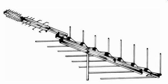
Fig. 5-2. A 35-element fringe antenna.
The antenna in Fig. 5-2 is an example of an all-coverage antenna for fringe use. It covers the vhf and uhf tv bands as well as fm. With a total of 35 elements it will receive tv signals on the vhf band up to 150 miles, and on the uhf and tv bands up to 90 miles.
If the tv stations around you broadcast service in Channels 2 to 13 only ( the vhf tv band), the antenna in Fig. 5-3 has al most the gain of the one in Fig. 5-2, but at considerably less cost. With its 23 elements it will bring in tv signals from up to 125 miles, and fm up to 100 miles.
In many areas, stations serving the fringe areas may transmit only on the uhf channels, 14 to 70. Also, sometimes the uhf translators on Channels 71 to 83 will be quite a distance from your home. In any case, the uhf antenna in Fig. 5-4 is an eight bay uhf only tv antenna capable of picking up signals in the uhf channels up to 100 miles away. It is not unidirectional, and is ideal for the reception of stations in different directions from your home.
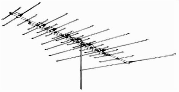
Fig. 5-3. Vhf/fm antenna.
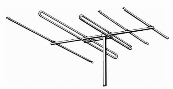
Fig. 5-5. High-gain fm antenna.
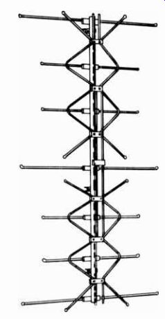
Fig. 5-4. Fringe uhf antenna.
For fringe area fm only, the fm antenna in Fig. 5-5 has high unidirectional characteristics, which give sufficient gain for a 110-mile range.
NEED FOR HEIGHT
The one factor for successful reception of tv in fringe areas, that of high-gain antennas, was described above. The other factor is the need for great height to overcome the effect of the horizon or other hilly obstructions. Height is important for both the transmitting and receiving antennas. The tv stations use the highest economical locations they can in order to serve as many viewers as possible. The height of the receiving antenna is up to the owner of the tv set.
One of the best ways of deciding just how much height is needed for your location is to check with neighbors in your area.
However, keep a few points in mind when checking with your neighbor. Is he using a black and white set? How much snow, if any, is there in the picture? How does his antenna compare with the one you plan on installing? Is he located on higher ground than your location? If you want good color reception, you will need a better installation than one for black and white.
Height above ground is not the only factor to consider. You must get above any high trees or other obstructions in the path of the signal. An antenna 40 feet above ground is about aver age for most fringe area installations.
Some areas of the country have the good fortune to be served by transmitting antennas that are quite high. Cities near mountains will usually have tv stations atop a nearby mountain. Los Angeles, Denver, and Albuquerque are among them. Such antenna systems can serve a wide area without necessarily needing high receiving tv antennas. One installed on the roof of the home is often sufficient.
MASTS AND TOWERS
The usual method for installing a tv antenna at great height is atop a mast or tower. Masts, like the one shown in Fig. 5-6, come in 20-, 30-, and 40-foot lengths. They are made in sections with graduated diameters that telescope into each other. The steel masts are hot-dipped galvanized and zinc coated for weather protection.
Towers are triangular or square-shaped structures with cross girders. They are usually made of steel. They are considerably more expensive than masts.
It is extremely important in the installation of a mast or tower to be sure it will withstand the highest possible wind that may be encountered in your area. Highest winds normally encountered are about 80 miles per hour, with some exceptions.
The exceptions are along the Atlantic seaboard and the coastal borders of the states along the Gulf of Mexico. In Wisconsin, along the shore of Lake Michigan, winds are known to exceed the 80 miles per hour mentioned.
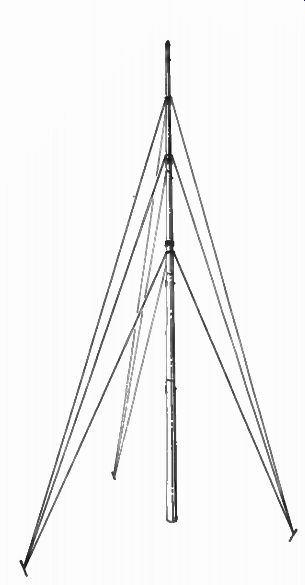
Fig. 5-6. Telescoping steel tower.
It is always best to include a safety factor. A 30% safety factor is recommended by the Electronic Industries Association, which means for highest normal 80 mile-an-hour winds, figure on about 110 miles per hour.
Towers up to fifty feet can usually be installed without guy wires. A two-foot square hole is dug. The mounting feet usually supplied with the mast are put in place, properly spaced to fit the bottom of the tower, and about a yard of concrete is poured into the hole. When the concrete is set, two of the bottom feet of ...

Fig. 5-7. Erecting a steel tower.
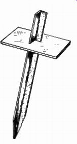
Fig. 5-8. Guy-wire stake.
... the tower are fastened to the mounting feet, and the tower pulled up into place. Steel towers are quite heavy, and will probably require the use of a gin pole, a tackle line, and two or three husky men to put them up ( Fig. 5-7) . Masts are not only less expensive, but considerably lighter in weight. A 40-foot mast only weighs about 33 pounds. All masts must be guyed, which means there must be enough room around the mast location for the guying stakes. Guying stakes should be placed about 10 feet from the base for each 20 feet of mast height. Radio-type, 6/18 guy wire is sufficiently strong to hold a 40-foot mast in any wind. Size 6/18 means six strands of size 18 galvanized iron wire twisted together. Stakes may be commercial type ( Fig. 5-8), or 5- to 10-foot lengths of concrete reinforcement rods, one inch in diameter. They are driven into the earth at an angle, each 120° apart.
Masts are light enough to be mounted on the roof of a house or other structure. It requires careful calculation of the length of the guy wires, which are fastened in place before the mast is raised onto the roof. Fig. 5-9 shows how this is done. The mast can be walked up after the guys are in place. Be sure the guy eye-screws are fastened into roof rafters, or they will surely pull out with a high wind.
The tv antenna, and rotator if used, must be installed on the tower or mast before they are raised. All lead-in and rotator cables must be connected and run down with standoff insulators beforehand. The antenna must be correctly orientated as to direction if a tower is used, as a tower cannot be rotated after it is up. A mast can be rotated after it is in the vertical position, however.
If tv transmitters are located in different directions, or if an offside hill develops a secondary signal path, a rotator is highly recommended. Rotators are geared-down, electric motors that turn the antenna to the direction desired. Some, like the two in the Archer line, have internal brakes to hold the antenna in its correct direction after rotation. Wind whip will not turn the antenna.
An important precaution: Be sure to install your antenna far enough from any electric lines so that it will not fall onto the lines in case it is blown down. Also consider any possible damage to buildings or other structures nearby, either those of your own, or those of your neighbor's. Leave plenty of room around your antenna system.

Fig. 5-9. Structure mounted mast.
Next: MULTIPLE-SET DISTRIBUTION
Prev: Link | --SPECIAL ANTENNAS FOR FM
AMAZON multi-meters discounts
AMAZON oscilloscope discounts
Also see:
Industrial Electronics (in the early 1960s)
199 Electronic Test & Alignment Techniques (1972)