It is a long road from the days of the simple rabbit ear antenna for indoor use, to today's multiple-tuned indoor antenna. Time was when the only tv stations on the air were in Channels 2 to 13, the vhf section of tv channels. And before the days of color tv, the simple rabbit ear with its telescoping elements did a pretty good job in locations where outdoor antennas were impossible. Sliding the elements in and out tuned the antenna to the channels in use.
DESIGN FOR TODAY'S
TV The evolution in the design of indoor antennas for tv follows the evolution of the increased services offered by tv.
When uhf channels came into use, the simple rabbit ears were not adequate. The elements were too long to resonate at the much higher frequency channels. The rabbit ears were maintained for the vhf section of the band, but elements were added for uhf, and they were made tunable. Fig. 8-1 illustrates one of the simplest of these. The large hairpin shaped element in the center was made tunable by a front knob and is resonated to the uhf channels. With resonance came proper impedance match, and better overall results. Fig. 8-2 shows another form of a similar antenna, using a double loop for the uhf channels.
Each have separate lines for connecting to the vhf and uhf terminals of the tv set.
Fig. 8-3 shows another indoor antenna for tv. It looks similar to those described above, but has improvements over them.
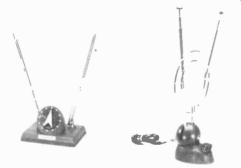
Fig. 8-1. Indoor antenna with tunable uhf hairpin loop. Fig. 8-2. Indoor
antenna with a uhf double loop.
The vhf elements and uhf loops are mounted on a rotating turntable for easy adjustment. The antenna has a uhf-vhf-fm selector and, a phasing switch for fine tuning.
Figs. 8-4 and 8-5 are similar except for the special loaning coils on the vhf elements of Fig. 8-5. Note the more elaborate uhf loops, the use of which gives better coverage of all uhf ...
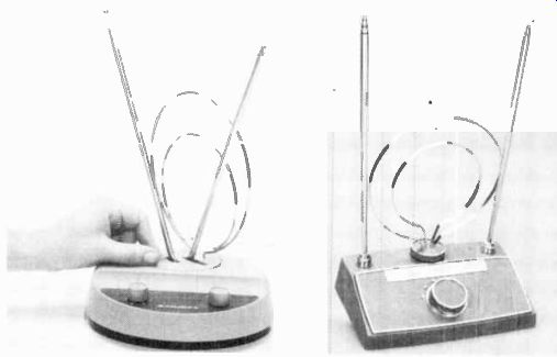
Fig. 8-3. Indoor antenna with a rotating turntable. Fig. 8-4. An indoor antenna
without loading coils.
... channels, along with the separate tuning controls. The antenna in Fig. 8-5 has discs in the low-frequency dipoles, which are called "power receptors." They add to the inductance of the low-frequency dipoles, with resulting better resonance in the vhf band. The "power receptors" electrically extend the length of the dipole arms, and therefore provide better reception with a minimum of arm adjustments.
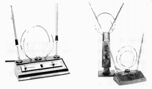
Fig. 8-5. " Power receptor" in the elements give better vhf
results.
Fig. 8-6. Indoor rotating television antennas.
SPECIAL ANTENNAS FOR COLOR
The indoor tv antennas described above will work well with color sets under close-in conditions, and where an outdoor antenna is out of the question. For better pickup they may be manually rotated. This requires turning the entire antenna. To be able to rotate the antenna portion only, and not the base, is an added feature of the following tv antennas.
In Fig. 8-6 the antenna in front has a rotatable uhf section.
It has the usual four section vhf dipoles and tuning device for the uhf section, like those described above. The rear antenna in the photograph has a tower-like construction which gives added height to the antenna elements and introduces a distinctively new style. The top section rotates both the vhf and the uhf sections of the antenna. The long vhf elements fold down when they are not in use.
AN "ULTIMATE" INDOOR TV ANTENNA
The antenna previously pictured in Fig. 3-18 has a six-section vhf elements, plus the "power receptor" loading discs. The uhf section has two fixed loops and one rotatable loop. Its rotation is controlled by a knob on the front panel. In addition, uhf is tuned from the front panel. An interference rejection filter is built in. For the family with a color set, and who wants the best possible results from an indoor tv antenna, this antenna represents today's ultimate design.
A weak signal on a black and white set may introduce some "snow" in the picture. The enjoyment factor is not too affected by this. However, a weak color signal to a color set causes loss of color, or a change of color. This is quite intolerable for the full enjoyment of color programs. Good color reception can be assured with the proper outdoor antenna. However, where circumstances prevent the use of an outdoor antenna, it is worth the set user's extra dollars to invest in the best possible indoor antenna. After all, the investment in the color set represents quite a considerable sum in itself.
Having purchased an indoor antenna it is wise to do some experimenting for best results. Experiment with locations in the room. The top of the tv set might seem to be the most convenient place for the antenna, but it is not necessarily the best place. An outdoor antenna has high forward directivity and reduces the possibility of "ghosts" or secondary images. An indoor antenna does not have this quality. Ghosts may be introduced by the return bounce of a secondary path signal from metallic objects in the room. If you encounter ghosts in the picture, move the antenna to another location. Try another, and still another. Find the spot that gives you the fewest ghosts, and the best hold to color pictures.
FM INDOOR ANTENNAS
Like tv, the best reception on a fm tuner or receiver is from an outdoor antenna. Next best is from a two-set coupler connected to a tv antenna, where the coupler feeds the tv set and the fm tuner.
The frequency range of fm is 88 to 108 MHz. Being only 20 MHz wide, it does not compare with the broad frequency spectrum of tv. For this reason many fm tuners are supplied with an indoor dipole made of 300-ohm twin line, like the one described in the section on fm antennas. While they work quite well they still cannot cover the full 20-MHz frequency width with equal response across the entire band. Nor can they be turned for best pickup if fm stations are in different directions, which is generally the case. The fm indoor antenna previously shown in Fig. 4-8, overcomes the two shortcomings mentioned above. The telescoping elements and tuned coil in the center provide precise tuning to the frequency to be received. In addition, the antenna can be turned on its base for best directivity.
As in the case of the color-tv reception, a stereo signal requires the reception of a much stronger signal for the multiplex control carrier to give good stereo separation. A tunable indoor antenna, such as this one, can give good stereo reception, short of an outdoor antenna.
Next: INSTALLING A ROTATOR
Prev: HOW TO INSTALL A TV ANTENNA
AMAZON multi-meters discounts
AMAZON oscilloscope discounts
Also see:
Industrial Electronics (in the early 1960s)
199 Electronic Test & Alignment Techniques (1972)