There are a number of advantages in using a rotator for a tv antenna. In fringe area reception, where the location may be between two cities with tv service, the advantage of being able to turn the tv antenna in the direction of either city is an obvious one. In such fringe area locations, no antenna installation should be contemplated without including a rotator.
Even in close-in metropolitan or suburban areas, there may be an advantage to the use of a rotator, depending on circum stances. In some cities not all tv stations are located in the same place. While the practice is for all stations to work together and all place their antennas on a single high point, this practice is not universal. Where this is not the case, the use of a rotator is a necessity, if best reception is desired from all stations.
Whether all tv station antennas are in the same place or not, there is almost always the problem of secondary paths, which result in ghosts in the picture. A highly directional receiving antenna should eliminate or substantially reduce the strength of the secondary path signal. But where this is not possible, a rotator can be the answer. A rotator can orient your antenna just enough in one direction or the other to turn it away from the secondary path signal, yet not lose enough primary path signal strength to affect reception. The proper use of a rotator can completely eliminate the ghost.
Fm station antennas are hardly ever located in one place.
If fm reception is as important to you as the reception of tv, include a rotator in your installation if for no other purpose than to turn your tv antenna ( it is assumed you are feeding both tv and fm tuner from the same antenna) in the direction of the fm transmitting antenna location. This is important to the best reception of stereo fm.
MANUAL AND AUTOMATIC ROTATORS
There are two basic types of rotator systems, manual and automatic. Each system consists of a rotating mechanism with an electric motor and reduction gears in a weatherproof housing, and a control box and indicator. The mechanism is located on top of the mast, and above it the antenna is mounted. The indicator is located in the house, on or near the tv set. A four or five-wire cable connects the two.
On manual rotator systems, the indicator has a lever or switch and a meter marked with compass points instead of numbers. The lever or switch is pressed in one direction or the other and held while watching the meter. When the needle on the meter shows the direction you want, the lever is released.
On automatic systems, a knob on the control box is set to the ...
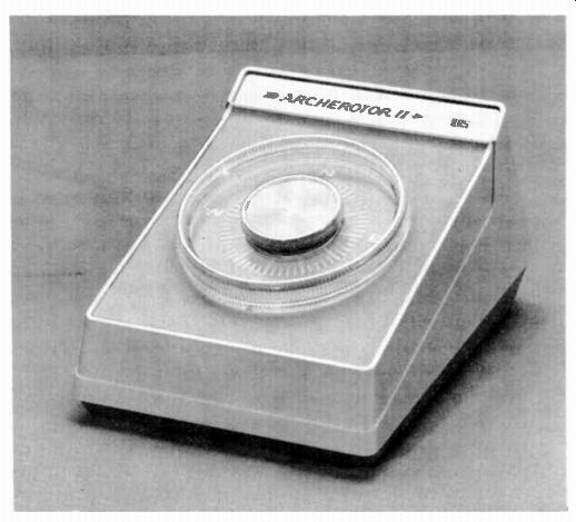
Fig. 9-1. Automatic rotator.
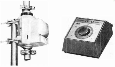
Fig. 9-2. Archer Servo- Rotor.
Fig. 9-3. Servo- Rotor control box.
... direction desired. The turning mechanism rotates the antenna until its direction matches the setting on the knob, then it stops.
The two Archer rotators pictured in this section are both automatic types. Both have knobs to set for the direction desired. In either unit the motor starts up and turns the antenna to the direction to which the knob has been set. Both include braking systems to hold the antenna in its set direction.
The rotator shown in Fig. 9-1 uses mechanical braking to hold the mechanism in its stopped position. The mechanism is held in a fixed position to the lower mast with two sets of bolts and serrated clamps ( similar to the mechanism mounting shown in Fig. 9-2). The bearings are fully weatherproof and lubricated for life. The control box contains the control dial and solid-state circuitry for handling the control of the motor.
The antenna may be turned in either direction but never more than a complete 360° circle. It uses four-wire control cable.
Fig. 9-2 pictures the Archer Servo-Rotor model rotator. It is a heavy-duty mechanism, husky enough to handle most applications. It is designed to accept upper mast sections of any size between 1% and 2% inches in diameter. The mast fits through the rotating bearing and is held in place by two clamps, one above and one below the mast section. A servomotor with dynamic clutch action is enclosed in the weatherproof housing.
The control box has the direction control knob, solid-state amplifier, and includes lights which show the direction of rotation ( Fig. 9-3). Just set the control knob to any position and the servomotor takes over. This rotor uses a five-wire control cable.
CONNECTING THE CONTROL CABLE
The interconnecting control cable may be four-wire, or five wire, depending on the rotator you purchase. In either case, one outside lead will have a means of identifying it from the others to assure that the wires are connected in proper order at both the mechanism and the control box. Skin back the insulation from each wire at one end. You will probably find that one wire has tin-plated strands of fine wire, and all others are plain copper.
Check the instructions received with the rotator to determine if the tin-plated lead is No. 1, or the highest number.
Remove the weatherproof cover on the rotator. Under the cover is a row of screw terminals. Skin the insulation from the several wires in the control cable and wrap one around each terminal, observing the number order given in the instructions. Wrap the wires around the terminals in a clockwise manner. Tighten down on the screws and replace the cover.
At the control box end, cut off excess cable and skin back the insulation of the individual wires. Connect them to the control box terminals in the same order and the same manner as for the rotator mechanism.
The control cable may be dressed close to the mast and taped to it at intervals down its length. No special precautions are required to keep this cable away from metallic objects (except 300-ohm unshielded twin line) . If the antenna cable is coaxial or if the 300-ohm cable is shielded, the control cable may be brought down and into the house along with and parallel to the shielded antenna cable. They may be taped together if that is convenient.
The unshielded, ribbon-like, 300-ohm twin line must not be run near the control cable, or any other cable or metallic material. This type of antenna lead-in must be brought down the mast using mast-mounted standoff insulators and carried down and into the house as described before.
ORIENTATING FOR DIRECTION
It is obvious that the antenna must point in the direction to which the control knob has been set. This is easy to achieve.
With the control unit wired to the cable, and the antenna and rotor installed, set the control knob to north. Return to the antenna installation and loosen either the bolts to the antenna or the bolts holding the rotor to the lower mast. Turn one or the other to point to the north, and retighten all bolts.
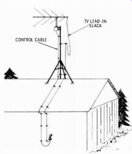
Fig. 9-4. Allowing sufficient slack in the tv cable.
CAUTION. The antenna lead-in cable must be given enough slack to allow the antenna to turn through a half-circle ( 180°) in either direction. The rotator does not turn the antenna continuously, but through a circle of 360° and back again. By securing the antenna lead-in at the half-circle point, only a half circle slack need be allowed.
With the antenna turned to point south, fasten the standoff insulators on the south side of the mast. Allow a loop of cable above the highest mounted standoff, leaving a generous amount of slack. As the antenna rotates to the north in either direction, the slack will be taken up, although it should not pull tight. Fig. 9-4 shows how to do this.
Next: ACCESSORIES FOR BETTER TV ENJOYMENT
Prev: INDOOR TV ANTENNAS
AMAZON multi-meters discounts
AMAZON oscilloscope discounts
Also see:
Industrial Electronics (in the early 1960s)
199 Electronic Test & Alignment Techniques (1972)