A Little Network Workout: We examine why the elimination of in audible ringing can, improve the sound of phono cartridges.
The pickup cartridge is one of the more critical components in the music reproduction chain, and although the moving-coil cartridge has improved lately, different ones produce different sound characteristics with respect to frequency balance, clarity, and imaging. Unfortunately, none of the usual specifications or measurements completely predict their sound. One thing that MC cartridges almost without exception have in common, however, is that they exhibit an under- damped high-frequency peak in their amplitude response, placed anywhere between 25 and 60kHz, due to the tip mass of the stylus/cantilever /generator reacting against the vinyl compliance.
We have experimented with loading the output of moving-coil cartridges with a shunt LCR network and found that it was possible to improve the sound by modifying the amplitude of the ultrasonic resonance. This improvement resulted in a tonal balance much more like that of a master tape without losing any of the transparency and detail typical of a good MC cartridge.
The importance of the resistive load across the output of cartridges was reported by J. Peter Moncrieff in 1980.[2] He found that a lower shunt (parallel) resistance reduced distortion levels: he postulated that the reduction in distortion was due to electromechanical damping being applied to motion of the stylus assembly (though others were unable to replicate his findings to anything like the same degree). A resistive load, however, cannot be reduced much below the cartridge’s internal impedance without lowering the output voltage to an unacceptable level. Moncrieff also showed that the resistive load did not affect the frequency response or lower the amplitude of the high- frequency resonance peak. This is an important point because it corrected a previously held belief that lower load resistances damped the high-frequency resonant peak.
Most cartridges have a reasonably flat frequency response through the audible frequency range to 20kHz, perhaps being 3dB up at 100Hz and 20kHz compared with the typical midband level, yet some sound more bright than such a measured response would indicate. We believe this tonal difference is mainly due to the dynamic behavior on the transients which are an inherent part of music. Fig.1 shows the transient ringing of a moving-coil cartridge tracking the 1kHz squarewave on CBS test record STR112. Note that the initial rise overshoots the squarewave top by about 30% and oscillation continues for most of the half-cycle.
Electromagnetic damping seemed to offer a way to minimize the amplitude of the peak and the resultant oscillation, so a circuit was devised to provide this damping at the appropriate frequency A two-element filter, involving a capacitor and inductor in series, placed across the cartridge’s output, gave a clearly evident improvement in sound, The results were optimized by calculation and experimentation. The resonant frequency can be found by counting the number of cycles of oscillation in one half of the 1kHz squarewave and multiplying by 2000.
The cartridge in fig.1, for example, resonates at about 38kHz. To reduce the level of this resonant oscillation, a capacitor-inductor (LC) combination is needed that will have minimum reactance at that frequency, given by:
F = 1/(2 Pi L C)
(where F is the resonant frequency in Hz, L is the inductance in Henries, and C is the capacitance in Farads).
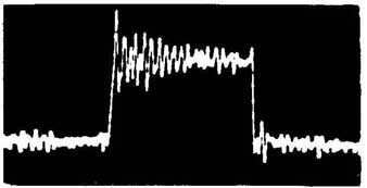
above: FIG. 1
There are, of course, an infinite number of LC combinations that will satisfy the formula: we found it practical to select a given value capacitor, wind a matching coil, and then test the results. In selecting LC combinations, as the value of capacitance is increased and the inductance decreased, the wider is the band of frequencies attenuated. Optimum results are obtained when L and C are selected so that the frequency response in the 15-20kHz region remains flat but the resonant frequency is damped. The optimum values for the cartridge in fig.1 are 0.15uF and 0.117mH. The capacitor is a high-quality polypropylene type, while the inductor was made on a ¼” diameter by 2 “long ferrite core with about 50 close-wound turns of #23 enameled copper wire. The effect of these values in parallel with a 100-ohm resistive load across the cartridge output can be seen in fig.2 (taken from a Gould model 4100 storage oscilloscope). Fig.2A clearly shows some improvement with a 0.15uF capacitor; fig.2B shows the effect of the LCR network.
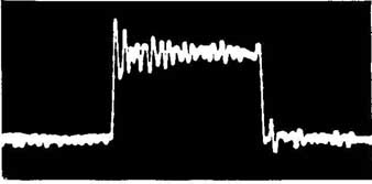
Fig. 2a
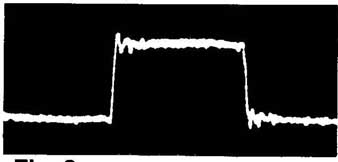
Fig. 2b
Fig.3 shows the effect of the LCR network on the cartridge’s steady-state sinewave frequency response using the CBS STR120 test record. (The cartridge was mounted in a Sumiko MMT arm on an Oracle table, and its output was recorded on a Urei-HP plotter.) The small wiggles are probably due to the test conditions, since they occur and overlay with various cartridges. The top curve is with the cartridge resistively loaded with 100 ohms; the resonant peak between 30 to 40kHz can be clearly seen. The second curve is with the 100 ohms now in parallel with 0.15uF; the peak is lower in amplitude. The third curve is with the LCR network; the peak has been eliminated. Note that response remains flat to beyond 20kHz.
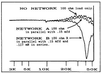
Fig.3
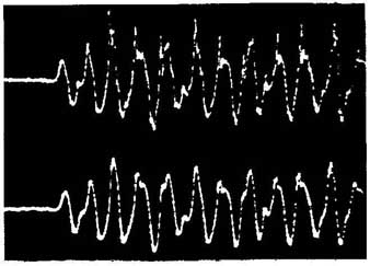
Fig. 4
Square waves are all very well, but what was the result using recorded music? We used the Orchestral Bells track on the Shure TTR-101 test record. The top trace in fig.4 is with the 100 ohm resistive load, the bottom trace is with the LCR load. The frequency of the struck bell is about 7kHz—the range where aberrations can cause harsh sound. The top trace shows overshoot and 38kHz ringing that increases the effective amplitude of the 7kHz tone. It is largely eliminated with the LCR circuit, as is shown in the bottom trace. This same effect is visible with the up per notes of a harpsichord.
The most significant audible improvement we found with the LCR circuit concerned tonal purity. The upper midrange and treble were cleaner and more harmonically correct. In addition, imaging was more precise and ambience more accurately reproduced.
This demonstrates why different cartridges with flat response in the audible range may nevertheless sound different in brightness— the higher the amplitude of the high-frequency peak, the brighter the sound. In other words, inaudible ringing above 20kHz appears to effectively increase the amplitude of signals occurring in the audible range, changing the perceived frequency response and leading to harsh or otherwise inaccurate reproduction.
Editorial Postscript:
The effects described above are undoubtedly real, but I doubt very much that they are due to increased electromagnetic damping of the generator assembly. A moving-coil cartridge is not very efficient at turning the mechanical energy imparted by the groove being dragged past it into electrical energy. If it was, say, 5% efficient, then even 100% electrical damping, from loading the cartridge output with a short circuit, would only influence its mechanical motion at resonance by 5%. Rather, I suspect that the very low impedance of the network at its own resonant frequency acts in conjunction with the cartridge source-impedance as a simple resistive divider to give an appropriately positioned notch filter, as is actually shown in fig.3.
I am also not sure that the explanation put forward as to why the presence of an ultra sonic resonance should result in a brighter sound is correct. In a linear system, it should have no effect. Perhaps the amplitude of the resonant vibrations is driving the cartridge into a nonlinear region of its behavior, resulting in the dumping of intermodulation products into the audio band, particularly if the preamplifier also has problems handling high-amplitude, high-frequency signals. In this case, however, filtering the ultrasonics would not change the cartridge’s basically nonlinear behavior.
One thing is certain, however: the proposed network does lower the amplitude of the HF resonance of their cartridge. I would like to hear from readers who have had similar experiences with LCR networks loading the outputs of their MC cartridges.
== FOOTNOTES ==
1 Watkins Engineering, 1019 E. center St., Kingsport, TN
2 International Audio Review 5, 1980 pp.31-159.
3 The squarewave ringing universally seen in the output of moving-coil cartridges when using this test record is at least somewhat due to ringing from the record cutter-head as engraved in the grooves of CBS STR112. Electron micrograph examination of the record confirm that the ringing is in the grooves; what cannot be established is the amount of ringing that accurately reproduces the record and the amount contributed by the cartridge. Both the network described the output of a moving-magnet rolloff ultrasonic frequencies, so the question is still open.
== == ==