We have discussed the various aspects which influence the survival rate of tubes from a more or less theoretical point of view. In this section, we will point out some practical steps which will take advantage of these natural laws and make them work to the benefit of the user.
Our first topic is cooling. Indeed, the most effective method of reducing all kinds of tube failures is to lower the temperature of their envelopes. The cooling of a vacuum tube starts out as a problem in radiation and then usually becomes one of conduction and convection. The heat generated within the tube is radiated toward the envelope which becomes heated and, in turn, heats the surrounding air by conduction. As the warmed air starts to move due to convection, new, cooler air comes in behind it and the process continues. If the air surrounding the tube is confined to a small space, its temperature soon rises to the point where very little difference exists between the air and bulb temperatures. The rate of cooling is slowed down and the bulb gets hotter and hotter and may eventually soften and melt.
The most obvious method for keeping bulb temperature down is to make sure that there is an unrestricted volume of air surrounding the tube so that air circulation is as free as possible. There are many circuit and mechanical considerations that frequently interfere with this objective. Shields, compartments, and cases or cabinets tend to restrict the free flow of air. Starting with tube shields, there are changes that can be made to improve the situation. Bright, shiny metal shields tend to reflect heat back into the tube. If their interiors are blackened, shields will then absorb heat more rapidly and can conduct it into the larger metal parts of the assembly, like the chassis, which act as "heat sinks." A heat sink is a large, heat absorbing body which permits the heat to be dispersed over more area and, hence, be more easily radiated or conducted into the surrounding air.
The simple laws of convection currents in air should be observed when mounting, or assembling apparatus using tubes. Heated air rises, bringing in cooler air below it. If a tube is mounted on a flat chassis pan, there is little available cool air to replace the warmed air surrounding it. If holes are punched in the chassis surrounding the socket, cool air can be drawn up through these holes and natural, convection cooling will be enhanced.
When chassis are mounted vertically, it is well to remember that the upper tubes will run somewhat hotter than those at the bottom, because heated air from the tubes at the bottom will provide less cooling when it reaches those at the top. If the hottest tubes are not located at the bottom, there will be a marked variation in the life of tubes in the enclosure.
Where many tubes are located in a small enclosure, or where the normal dissipation of even a few tubes is quite high, ordinary free air circulation may not provide sufficient cooling. Under these conditions, forced-air cooling will be found very beneficial. In fact, forced-air cooling can almost always be counted on to increase over-all tube life by as much as 100 percent. In controlled life tests in the factory, the effects of forced-air cooling can be easily demonstrated.
MEASURING BULB TEMPERATURE
There are three methods for measuring the effectiveness of any experimental cooling system. The first is to simply place a thermometer inside the enclosure and read it after an hour of operation. The temperature of the air inside the enclosure will give a relative indication of the effectiveness of any changes which are made in the ventilation of the enclosure. Of course, the real concern is bulb temperature. Nevertheless, the air temperature within the enclosure is a good indication of the rate at which the heat is being drawn off. If the inside temperature is not too far above that of the outside air, there is probably no serious problem. But if the inside temperature is fairly high, the next thing to do is to measure actual bulb temperatures.
There are several methods by which this can be done.
The simplest is to use temperature-calibrated wax sticks, known as Temple sticks. They come in sets with their melting temperature indicated on each one. Several sticks can be used to "bracket" the temperature of the bulb by noting which one melts and which one does not.
A thermocouple attached to the bulb with some kind of putty will read the temperature very accurately. If this is not available, a laboratory thermometer can be attached to the tube with a patch of putty, and it will give a reliable indication if the thermometer bulb is in contact with the tube bulb. The question of what temperature is desirable is difficult to answer. There is no magic number. The lower the temperature can be held, the better will be the results.
There is a close relationship between bulb temperature and over-all life. A drop of even a few degrees will have some beneficial effects.
DISSIPATION CONTROL
It is interesting to note that bulb temperature can also be used as a valuable indication of operation efficiency in the case of many Class B and Class C tubes, and certain pulse applications. It is a fact that it is only the heat wasted in a tube which causes the bulb to heat. In many power tube applications, this heat is a direct indication of the amount of power which is not reaching the intended useful load. By adjusting circuit values so as to develop the minimum amount of heat while still accomplishing the intended function for which the circuit is designed, the maximum utilization of power will be accomplished. This may actually result in improved output while still achieving longer tube life. An efficiently operated power stage (one that wastes as little power as possible in heating up the tube and the air around it) will deliver more power to its load, and will live longer in doing it, than an in efficiently operating one.
This is often true in such applications as horizontal deflection amplifiers in television. If a check is made of various drive conditions and the bulb temperature is measured at each, one will be found which produces optimum output and minimum bulb temperature. This is also the condition which assures the very best possible life for that tube.
In the case of rectifiers, bulb temperature may often be reduced by limiting the peak current while not greatly affecting the average output. This results because with some transformer designs, the leakage reactance is so low there is almost no limit to the flow of peak currents except for the internal tube resistance or "tube drop." These peak currents flow every cycle and may be rather high in amperes; yet, they contribute little to the steady-state DC current supplied to the load. By installing a low value of resistance in series with each plate, these peak currents can be reduced and the heat removed to these resistors.
This will effectively reduce the temperature of the rectifier tubes and will increase their useful life.
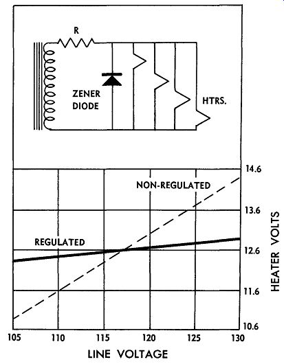
Fig. 1. Zener-diode regulator and chart, showing the improvement
of the voltage stability.
VOLTAGE AND CURRENT REGULATION
Voltage control or regulation is probably the second largest area for improving over-all tube life. The most important tube voltage to control is that applied to the filaments or heaters. There are many ways of accomplishing this objective. Saturable reactors are available which can maintain their output within a few percent. These can be applied to the primary voltage sources and when this is done, the improvement will be most noticeable.
There are excellent ways of regulating heater voltages only. One of these is through the use of a zener-diode regulator as shown in Fig. 1. The chart accompanying this simple circuit illustrates the immense improvement which can be accomplished in terms of voltage stability.
The effect upon the life of regulated tubes will depend upon many other factors; however, a two-to-one improvement is not unusual, especially where line surges are fairly common.
The history of power line voltages in this country has been invariably upwards. Twenty-five to thirty years ago the standard line voltage was 110 volts. During the years that followed, this voltage kept creeping up until a new standard of 117 volts was agreed upon. The increase is still in evidence today, and many sections of the country now report 125 volts, and in some cases, 130 volts as being not uncommon. Because of this, it is a good idea to design equipment that is intended to be very reliable with this trend in mind.
LOW-VOLTAGE OPERATION
Tubes are designed to be operated at their rated filament voltages. To get the best over-all satisfaction from their use, they should be operated as near this value as possible. However, where this is not possible, it is safer to err on the low side than it is on the high side. In other words, if they are operated at 5 to 10 percent below their rated center value, they may possibly fail to give quite as many hours of service at the remote end of their life span, but they are not apt to suffer from as many complications, or be prone to catastrophic failures as if they are operated at 5 to 10 percent above their ratings. Where line voltages are known to be high or unstable, the use of auto transformers to reduce the voltage a fixed percentage will be a great help in stretching tube life.
Where many tubes are involved in a single piece of equipment, as in various computers, broadcast studios, and in some forms of processing, it becomes important to consider the advantages to be gained from continuous heater operation. There is much experimental data to prove that intermittent operation of heaters is more destructive than steady burning. There are the economics of power consumption to be weighed; however, from a strict life point of view, it would seem much better never to turn off such apparatus. One compromise to economy can be made by not turning such equipment off, but merely turning it down. Placing heaters on about 50 percent of their rated voltage will keep them warm and will prevent the shock of beginning operation from a cold start.
In this connection, there is much that can be done to improve the life of tubes which are switched on and off regularly. Damage to heaters is caused by the heavy surge current which flows when tubes are first turned on from a cold start. If some form of limiting resistor is placed in series with them, this surge can be largely eliminated, and with it the harmful aspects of their being turned on and off.
There are many forms of these devices on the market.
They go under various trade names, such as Surgister, Thermister, Tube Protector, Tube Sentry, Fuse Resistor, and Globar. They are quite inexpensive and easily in stalled. Some can even be installed in the power line out side the actual equipment.
They consist of two general types, one of which is the simple negative temperature coefficient resistor which has its maximum resistance when cold and drops to a low value when heated. The second type includes a bi metallic switch which is actuated by the heating of the resistor. This switch is in series with the high voltage so that the voltage is delayed until all tubes have reached their full operating temperature. This matter of voltage delay is important to prolonging the life of rectifier and damper tubes. It may indirectly save other tubes by reducing the number of voltage breakdowns in capacitors and transformers caused by the high initial voltage often present before the tubes reach maximum conduction.
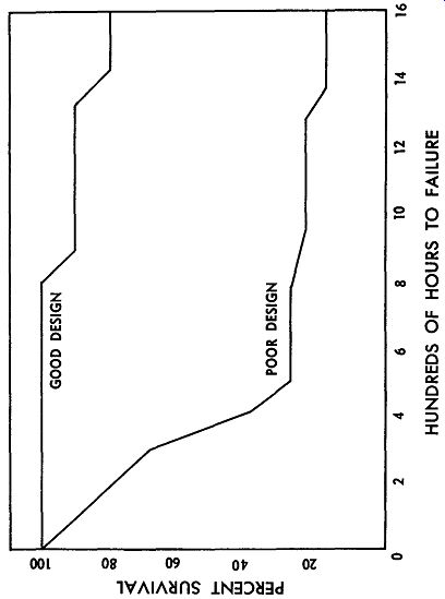
Fig. 2. Life-test results of two similar pieces of apparatus, both
with the same kind of tubes and tested under the same conditions.
MECHANICAL
Some tubes are inherently sensitive to mechanical jar ring or vibration. This is usually true in high-gain audio circuits, or video amplifiers. Instead of searching for tubes that will remain free of microphonics in such applications, it is often simpler and more rewarding to make slight revisions in the method of mounting the tube. If the socket can be remounted using rubber grommets and cup washers, the tolerance to chassis-transmitted vibration will be greatly improved. Using weighted shields over the tube, in addition to the shock mounting, will reduce pickup of air-borne vibrations.
MAINTENANCE
Certain maintenance practices reduce failures while certain others tend to increase them. These were discussed in a previous section from the theoretical point of view.
Here we would like to make certain specific recommendations which, if carried out, will go a long way towards reducing maintenance-caused failures.
Never test any tube if you can possibly avoid doing so.
Testing never improved a tube's condition and it can frequently do them a lot of harm. Leave this highly complicated business to experts. Concentrate your efforts on testing equipment with the tubes in their sockets. In this connection, it is frequently advisable to add jacks or to bring out test points so that tubes and circuits can be measured in their functioning condition. The fewer times you disturb tubes, the more reliable they will prove to be.
Recognize the fact that tubes don't just fail - there must be a reason! More often than not, the reason is completely within your province and you can eliminate it if you know how. Do not overestimate the capabilities of tube checkers and thus be led into a sense of false security.
Become more familiar with the characteristics and symptoms of tubes as they really are. Soon you will realize there is really nothing so unreliable about tubes that more reliable applications couldn't cure.
This is borne out by Fig. 2, which shows the results of life tests conducted on two similar pieces of apparatus, both using the same kind of tubes and tested under the same conditions. Similar mass studies have been con ducted by the military and they all bear out the same simple truth.
Most tube failures in equipment can be attributed to designs that don't take into consideration the basic nature of tubes and, therefore, are not designed with them in mind. It is hoped that some of the facts that have been disclosed in this guide will inspire designers and maintenance people to recognize these truths and that through them, they may enjoy greater tube life and reliability.