Power supplies and their associated circuitry are the source of various obscure trouble symptoms that can cause excessive waste of time in random hit-or-miss approaches. Poor sync action, raster shadowing, loss of interlacing, and audio interference in the picture are typical of these trouble symptoms. Voltage measurements seldom provide useful clues, because the basic difficulty is ac contamination of the dc supply voltages. Hence, a scope can be a valuable timesaver in localizing power-supply troubles.
STACKED B+ CONFIGURATION

Fig. 10-1. Audio-output tube is also used as a B+ voltage divider.
Many modern receivers use a stacked B + section in the power-supply system, as shown in Fig. 10-1. The audio-output tube doubles as a B+ voltage divider, in order to reduce manufacturing costs. The normal ripple waveform at the audio-output cathode is shown in Fig. 10-2A. Obscure symptoms can arise if the 200-uF filter capacitor becomes low in value (Fig. 10-2B). The dc supply voltages remain about the same, but sound modulation appears in the picture, and sync action becomes unstable. A scope check at the output of the 240-volt power supply may show a ripple voltage below the maximum amplitude specified in the receiver service data. However, a check across the 200-uF filter capacitor immediately reveals the trouble.
When an audio-output tube is used as a voltage divider, the B+ voltage must be filtered once again in the circuit following the cathode of the tube. The reason is that the de supply voltage becomes contaminated with audio signal through the output tube. This initial filtering is done, in Fig. 10-1, by the 200-uF capacitor, and is followed by a second filter section which supplies the video-output tube. The latter section not only provides a smooth dc supply to the video section, but also serves to decouple the video amplifier from the i-f and rf sections. Note that the 30-uF capacitor is shunted by a 5000-pF capacitor. The purpose of the small capacitor is to provide a low-impedance bypass to ground for high-frequency ac voltages.
Large electrolytic capacitors often have appreciable inductance, which lessens their effectiveness in high-frequency circuits.

Fig. 10-2. Ripple wave at cathode of audio-output tube when 200-uF bypass
capacitor is defective. (A) Normal ripple. (B) Abnormal ripple.

Fig. 10-3. A transformer-type power supply.
INPUT WAVEFORM TO FILTER
A typical transformer power-supply circuit is shown in Fig. 10-3.
The input waveform to the filter is checked at point A. It might be supposed that this waveform would be the same in all receivers, but this is not the case. Depending on the number of sections in the filter, use of inductors or resistors between sections, and current drain from the different sections, this input waveform varies. Two common examples are illustrated in Fig. 10-4.
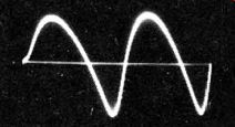
The input waveform approximates a sawtooth when the input impedance of the filter is essentially capacitive, because of appreciable resistive isolation between sections. The sawtooth waveform is generated because the rectifier conducts in pulses (it is back-biased by the B+ voltage), and the input filter capacitor is suddenly charged by each pulse. The capacitor discharges exponentially between pulses and supplies dc current to the filter sections following. The nature of this pulse-charging sequence is seen in Fig. 10-5. This is the current in a transformerless-type receiver. The waveform shows both the heater and filter current in the line. The heater current is a sine wave and is superimposed on the pulse current drawn by the rectifiers. A pulse current waveform by itself is shown in Fig. 10-6.

Fig. 10-4. Typical waveforms at filter input.

Fig. 10-5. Filter draws pulses of current from the rectifier.
Fig. 10-6. Pulse current without a sine-wave component.
In the Fig. 10-3 configuration, a filter choke is connected between the sections. A choke normally has appreciable inductance and comparatively low resistance. The inductive reactance modifies in the input voltage wave, as seen in the right-hand photo of Fig. 10-4.
Depending on inductance and capacitance values and current drain, the waveform may also be unsymmetrical (tilted), as seen in Fig. 10-7.
In any event, the essential point is that the power supply has normal operating waveforms (and amplitudes) which are characteristic of its configuration and demand. These characteristics can be checked in the receiver service data, or by comparison with the waveforms in a similar chassis. If a component is defective or if a branch current is not normal, waveshapes and amplitudes change to a greater or lesser extent, depending on the severity of the trouble condition.

Fig. 10-7. Unsymmetrical waveform at filter input.
INCIDENTAL BYPASSING FUNCTION
Power-supply waveforms generally contain details which reflect circuit action in various receiver sections (Fig. 10-7). In older receivers or elaborate modern receivers, extensive filtering is provided, which results in "clean" input waveforms. Waveforms across output filter capacitors, on the other hand, are generally contaminated with residues from the sweep circuits in particular, and sometimes from other circuits as well. Economy-type receivers display appreciable contamination of the input waveform also, because of simplified power-supply circuitry.
Both horizontal and vertical sweep residues are prominent in the Fig. 10-8 waveform. The residues appear because the sweep circuits are not decoupled individually from the power supply, in which the filter capacitors are also serving a decoupling function. Because their bypassing action is somewhat incomplete, the sweep residues appear in the power-supply waveform. The horizontal-sweep residue is seen as a "picket-fence" interference in the main waveform. The vertical sweep residue appears as different heights of alternate peaks.

Fig. 10-8. Alternate peaks of the signal have different heights.
The vertical-output stage has a comparatively heavy current demand and operated at 60 Hz. The full-wave rectifier, however, generates a 120-Hz ripple. Therefore, the vertical sweep-current demand is imposed on every other peak of the ripple waveform. A power supply, like any voltage source, has a certain source impedance; and when current demand rises, the voltage output drops. The lower the source impedance, the better the regulation and the less the amplitude variation on alternate ripple peaks. The essential point here is that the ratio of peak amplitudes is an indicator of the power-supply regulation, and this is duly noted by the experienced technician. Poor regulation can result from loss of filter capacitance, poor power factor, high forward resistance in contact rectifiers, or defective filter chokes.
In a voltage-doubler on half -wave power supply, the ripple frequency is 60 Hz and the vertical sweep-current demand occurs on each peak of the ripple waveform. Thus, if the receiver is tuned to a local tv station, the vertical-sweep residue will be effectively masked by the ripple waveform. Again, if the receiver is tuned to a distant station or if a conventional pattern generator is used, the vertical-sweep residue "snakes" through the ripple waveform, and its amplitude is plainly evident. The reason for this is that power companies in remote areas do not have exactly the same frequency as the local power company, and ordinary pattern generators do not have the vertical sweep oscillator locked to the power-line frequency. Again, if the receiver is tuned to a local station, the vertical-sweep residue will "snake" through the ripple waveform if the vertical-hold control is misadjusted to make the picture roll.
CURRENT WAVEFORMS
A dc meter can be connected in series with any branch of the power-supply circuit, but it shows only the value of the dc current component. This information can be useful on occasion, however. The ac current, which is of primary concern in troubleshooting procedures, can be checked properly only with a scope. Note that an ac meter reads inaccurately because of the waveform error (power supply waveforms are not sine waves), unless a peak-to-peak meter is used. The latter will show the true amplitude of the ac waveform.
In the final analysis, a scope is the most satisfactory indicator of current waveforms.
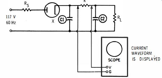
Service checks of current waveforms are commonly hampered by the necessity for inserting a small resistance in series with the circuit under test, and connecting the scope across the resistor. There are exceptions, of course. For example, if a scope is connected across the 470-ohm resistor in Fig. 10-1 (which is already in the circuit), the current in this supply line will be displayed. If a filter resistor is between two filter capacitors, the scope can be connected across the filter resistor to display the current in this part of the circuit. Some receivers have a fuse resistor which makes a convenient current waveform test point.
Inasmuch as current waveforms are generally unspecified, technicians make use of comparison tests in similar chassis. Comparison tests can localize a defective component quickly. Remember that ordinary scopes operate with a "hot" case when such tests are made; therefore, use caution to avoid a shock! Incidentally, it is interesting to note here that ac probes are now available for scopes, but they are expensive. Such ac probes are quite convenient, because no connection is required to the circuit under test. The probe is merely clamped around the lead, and the current waveform appears on the scope screen. Current probes are calibrated so that peak-to-peak currents can be read from the scope pattern. A current probe, of course, leaves the scope case "cold." It permits a quick and accurate test of the ac being drawn by each circuit branch. If used with dc scope, it also shows the value of dc being drawn by each branch.
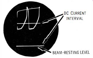
The characteristics of current indication by a dc scope are shown in Fig. 10-9. The ac waveform rises above the beam-resting level by an amount which shows the value of dc present. The amplitudes of the ac and dc waveforms are measured in peak-to-peak volts. That is, dc and peak-to-peak volts have equal units on a calibrated scope.

Fig. 10-9. Ac and dc current indication.

Fig. 10-10. Scope case is "hot" in this above-ground test.

Fig. 10-11. Balanced vertical input.

Fig. 10-12. Input circuits. (A) Ordinary input. (B) Balanced input.
"ABOVE-GROUND" TEST METHODS
Just as current waveforms can be checked effortlessly in any circuit branch when a current probe is used, modern methods are available for checking voltage waveforms in any circuit without difficulty. As a simple example, consider again the test illustrated in Fig. 10-10. The scope displays the voltage waveform across the resistor. The waveform is, of course, identical with the current in the lead from the first to the second filter capacitor. The "hot" scope case is a possible source of shock to the operator, and is the outstanding difficulty here.
Several service-type scopes are designed to eliminate this difficulty by providing a balanced input to the vertical amplifier in the scope.
(Balanced input is also called push-pull input, double-ended input, or differential input.) Fig. 10-11 shows how this type of scope has two vertical-input terminals and a ground terminal. The ground terminal is usually connected to the chassis of the receiver under test, or it may be left unconnected if the scope is well designed. The two vertical input leads are used in exactly the same manner as the single vertical lead and ground lead of an ordinary scope. The chief advantage of this method is that the two vertical-input leads can be connected across any power-supply component without making the scope case "hot." The case is always at ground potential.
Balanced input is obtained by simple circuitry, as shown in Fig. 10-12. Nearly all present-day scopes use paraphase vertical amplifiers.
These are push-pull amplifiers with a common cathode resistor. In an ordinary scope, the grid of one tube is grounded, as shown in Fig. 10-12A. However, the grids of both tubes are driven in a scope with balanced input, as seen in Fig. 10-12B. Either input A or B can be used as a "hot" lead and the other as a ground lead, or both inputs A and B can be used as "hot" leads in above-ground tests. This latter use is quite important. Thus, if a scope has balanced input, all the tests which are possible with an ordinary scope can be made, plus above-ground tests which are difficult with ordinary scopes.