The sync separator is a branch of the signal channel. Its purpose is to clip the sync tips from the composite video signal. The separated sync signal is then used to synchronize the horizontal and vertical oscillators.
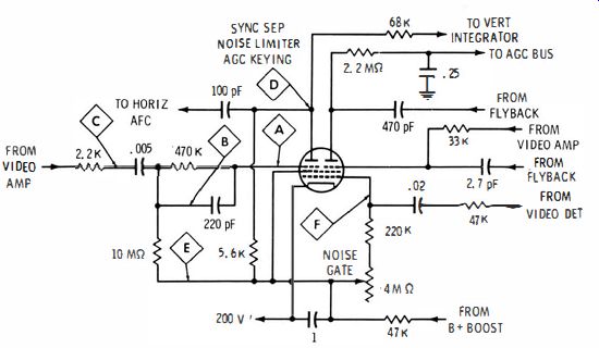
Fig. 5-1. Typical sync-separator configuration.
THE BUS CIRCUIT
A typical sync-separator circuit used in modern receivers is shown in Fig. 5-1. Sync separation (and noise limiting) occurs in the left hand section of the tube. The other section is the agc keyer.
The normal input signal to the sync separator is shown in Fig. 5-2.
It is checked at point A with a low-capacitance probe. (Unless an input signal is applied to the receiver from a pattern generator or tv antenna, only a random noise pattern appears.) Its normal amplitude is about 30 volts peak to peak. Although sync lock is maintained at lower amplitudes, substantial attenuation results in unstable sync or complete loss of synchronization. If the amplitude of the signal at point A is low, check the signal at points B and C. An open capacitor in the grid circuit causes excessive attenuation and waveform distortion. If the .005-uF coupling capacitor is leaky, the dc grid bias on the tube will be changed and the tube and circuit characteristics will be shifted. As a result, the waveform at point A will become blurry and attenuated (Fig. 5-3). If the signal is normal at point A, the next check is made at point D, the plate of the sync separator. The normal waveform at this point consists of cleanly separated sync pulses (Fig. 5-4), with only a slight trace of residual video signal along the top. If the waveform is normal at point D, horizontal locking trouble is logically sought in the afc or horizontal-oscillator section. Likewise, vertical locking trouble will be due to a defect in the vertical integrator or vertical oscillator. But in the event that the waveform at point D is not normal and has appreciable residual video signal (Fig. 5-5), there is probably a defective component in the plate circuit. The 100-pF coupling capacitor may be leaky, for example.

Fig. 5-2. Normal input to sync separator.
Fig. 5-3. Coupling capacitor leaky.
Faulty sync separation can also be caused by a defect in the cathode circuit. In order to trace this signal, check the waveform at point E. A low-amplitude video signal (about 5 volts peak to peak) normally appears. Little or no signal at this point commonly is caused by leakage in the O. I-J-LF cathode bypass capacitor. However, if this capacitor is open, sync separation is not so seriously disturbed.
The first grid in the tube (Fig. 5- 1) is common to both sections.
It operates in the noise-gate circuit. A low-amplitude negative-going signal (about 0.2 volt peak to peak) from the video detector is applied to point F, and appears as shown in Fig. 5-6. The signal amplitude is normally too low to affect sync separation unless a high-level noise pulse arrives. The high negative peak voltage of the noise pulse cuts the tube off for the duration of the pulse. Thus, a "hole" is punched in the separator output signal, and sync stability is far better than if the noise-gate circuit were not used.
In case the .02- uF coupling capacitor to the noise-gate grid is open, the negative-going video signal obviously does not feed into the grid circuit, and the noise gate becomes inoperative. This is of no consequence during strong-signal reception. Horizontal sync becomes less stable, however, on weak and noisy channels, because high-level noise pulses then feed through to the afc circuit. However, if the .02- uF coupling capacitor is leaky, the picture disappears and no video signal is found at point F. What happens here is that dc voltage bleeds through to the video detector and "kills" the video signal, unless the noise-gate control is set to a high resistance.

Fig. 5-4. Normal separated sync signal.

Fig. 5-5. Unsatisfactory sync separation.

Fig. 5-6. Negative-going noise gate.

Fig. 5-7. Distortion of video signal, caused by loss of horizontal sync.
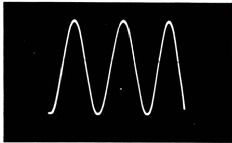
Fig. 5-8. Centered sine-wave pattern.
The foregoing explanation of sync separation is typical. Although numerous variations in circuitry occur, particularly in older types of chassis, the general principles are the same. The sync separator always operates to strip the sync tips from the composite video signal, permitting the passage of little or no residual video. If a noise-gate circuit is used, its action is to punch a "hole" in the separated sync signal for the duration of high-level noise pulses. The technician should consult the receiver service data in each case, to determine the normal waveforms and peak-to-peak voltages.
One note of caution-the normal waveforms are sometimes distorted because of reflected trouble from the horizontal-afc or -oscillator circuit. Receivers having keyed agc may generate spurious ac voltages on the agc line when the picture is out of horizontal sync. This spurious ac can "chop up" the video-signal input to the sync separator, as shown in Fig. 5-7. To avoid being misled in this situation, clamp the agc line with a bias box or a battery before checking waveforms in the sync section.

Fig. 5-9. Display of positive and negative pulses. (A) Positive pulse. (B)
Negative pulse.
READJUSTMENT OF VERTICAL-CENTERING CONTROL
In signal-tracing procedures, the scope pattern may not be centered on the screen. This depends on the waveform. Readjustment of the vertical-centering control is sometimes required to prevent the top or bottom of the waveform from extending off-screen. Fig. 5-8 shows a sine-wave pattern centered on the screen. If the beam-resting level is centered, the sine-wave pattern will also be centered, in consequence of the waveform symmetry.
Next consider the display of a positive or negative pulse voltage, as in Fig. 5-9. With the beam-resting level centered on the screen, the pulse waveforms are de-centered upward or downward, depending on the pulse polarity. The vertical-centering control must be readjusted to center the pulse waveform. Service scopes do not have automatic centering circuits. Therefore, whenever the waveform is poorly centered, the operator must readjust the vertical-centering control.
Some specialized scopes do have automatic centering circuits. This is accomplished by use of a dc restorer diode, as shown in Fig. 5-10.
The beam-resting level is adjusted to a suitable point, such as one inch from the bottom of the screen. Then, when a waveform voltage is being displayed, the restorer automatically generates a dc bias which clamps the bottom of the waveform to the preset level. Either a positive or a negative pulse appears with the lower peak of the waveform clamped to this level. Thus, with the vertical-gain control adjusted for normal pattern height, all waveforms are automatically centered on the screen, regardless of their shape.
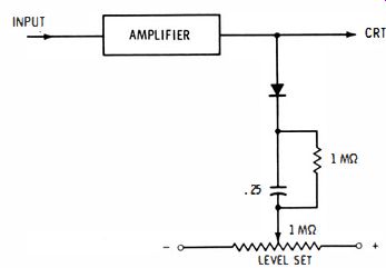
Fig. 5-10. Circuit for automatic centering.
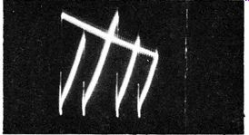
Fig. 5-11. Waveform with alternate symmetry.
SWEEP FREQUENCY FOR WAVEFORMS WITH ALTERNATE SYMMETRY
Sometimes waveforms have alternate symmetry, as seen in Fig. S-I I. Adjacent peaks have different voltages, but alternate peaks have the same voltage. These waveforms must be displayed with an even number of peaks in the pattern, i.e., two, four, etc. If you attempt to display a pattern with one peak or three peaks, for example, the result will be an unsatisfactory blur. The reason for this is that the sweep oscillator locks in first on a low peak, and then on a high peak, when an odd number of peaks is displayed. Thus high and low peaks overlap, or the waveform "jumps one step" on each forward trace. This makes a blurred display. On the other hand, with an even number of peaks in the pattern, the sweep oscillator locks each time on the same type of peak. The result is a clear pattern.
An even number of peaks is displayed in the pattern when the fine-frequency control is adjusted to a suitable point. If the pattern locks in a blurred aspect at first, merely turn the fine-frequency control higher or lower. As the next locking frequency is approached, an un-blurred pattern will suddenly fall into lock. This is not a difficult point in scope operation, but it may be confusing to the beginner.
Receiver service data generally recommend the display of two complete cycles in reference patterns. If this rule is followed, blurred and overlapping displays will not occur.
Waveforms with alternate symmetry are commonly found when checking the B + supply voltage to a sync-separator or sync-amplifier tube, for example. There may be excessive ripple voltage on the supply line, because of defective decoupling capacitors or failing filter capacitors in the power supply. Excessive ripple modulates the sync signal and can cause picture pulling and rolling, or complete loss of sync.
Typical causes of alternate symmetry are as follows. The vertical output stage usually has a heavy current demand at 60-Hz intervals.
The power-supply ripple frequency in many receivers, however, is 120 Hz. With marginal filter capacitors or faulty decoupling circuits, these two ripple waveforms beat, and the resultant ripple waveform has alternate symmetry.
The 120-Hz ripple from a full-wave power supply displays more or less alternate symmetry unless the secondary of the power transformer is center-tapped exactly (equal voltages applied to each rectifier), and unless each rectifier has the same plate resistance (or front-to-back ratio in contact rectifiers). Also, one side of the center-tapped secondary may be loaded by an auxiliary half-wave power supply in some receivers.
SYNC SEPARATOR WITH PHASE-INVERTER STAGE
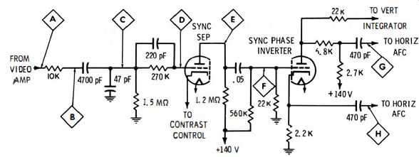
Fig. 5-12. Sync-separator and phase-inverter configuration.
Many tv receivers have a sync-separator triode followed by a phase inverter stage, as shown in Fig. 5- 12. The separator operates as discussed previously, with composite video signal at points A through D. The signal amplitude is about 30 percent lower at point D than at point A. The 10K resistor prevents the separator input from loading the video amplifier objectionably. Between points B and D, the RC network serves to attenuate noise impulses to some extent. In turn, the horizontal sync pulse at point D normally appears rounded, compared with its shape at point A. If the output signal at point E is weak or absent, check with a low-capacitance probe from point A through point D. Normal output from the sync separator is shown in Fig. 5- 13. If an open, leaky, or shorted capacitor or an off-value resistor is attenuating or distorting the grid-input signal, the separator output will be affected accordingly.
The waveform amplitude from point E to point F does not change appreciably in normal operation. However, there is somewhat less residual video signal at point F because of the filtering action of the RC coupling network. Normal amplitude at point F is about 15 volts peak to peak. If substantially less, check the .05-uF coupling capacitor. If the capacitor is open, horizontal-sync lock becomes quite unstable, vertical-sync lock is lost completely, and the picture rolls. The vertical-sync pulse is completely unable to couple into the phase inverter grid via stray capacitance, while a residue of horizontal sync does transfer.
Phase-Inverter Action
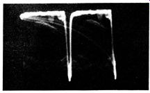
Fig. 5-13. Normal sync-separator output signal.
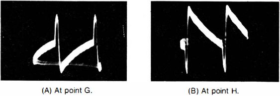
Fig. 5-14. Phase-inverter outputs. (A) At point G. (B) At point H.
The sync phase inverter provides stripped sync pulses in opposite polarities to the afc section. Outputs are taken from both the plate and the cathode of the inverter triode. These waveforms are of the opposite polarity, as shown in Fig. 5- 14. Note how sawtooth components are added to the waveforms at points G and H. These are comparison waveforms from the sweep section which are fed back into the afc circuit. Thus, waveforms at the inverter output are a combination of signal and self-generated voltages.
How does the inverter stage work? Recall that the output from a triode amplifier (plate output) has a 180 deg phase shift with respect to the grid-input signal. That is, the plate output for a complex wave-form is "turned upside down" with respect to the grid waveform.
Also, the output from a cathode follower has 0 phase shift with respect to the grid-input signal, that is, the cathode output is a replica of the grid input. The phase-inverter stage combines these two circuit actions.
Suppose one of the 470-pF coupling capacitors is open. Only the sawtooth component will be displayed in the Fig. 5- 14 waveform. If there were a defect in the sawtooth feedback circuit in the afc section, only the sync-pulse component would be displayed in the Fig. 5-14 waveform.
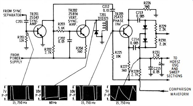
Fig. 5-15. A typical transistor sync amplifier and afc section, with separate
vertical-sync amplifier.
Under normal conditions, the sync-pulse amplitudes are approximately equal at points G and H in Fig. 5- 12. If you find a substantial difference in amplitudes, check the resistors in the inverter output circuit. A change in load impedance causes a corresponding change in waveform amplitude. The waveform detail at points G and H is not identical because the inverter plate feeds the vertical integrator as well as the afc circuit. The plate-load impedance has a somewhat different reactance from the cathode-load impedance in the inverter stage.
The waveforms in Fig. 5-14 represent the display for a picture in horizontal sync. If the picture is tearing or out of sync, the relationship of the pulse to the sawtooth changes. Try then to adjust the horizontal-hold control so that the picture is in horizontal sync. If it is impossible to hold the picture in lock, the sync pulses will "ride" the sawtooth component. Although the pattern is more difficult to evaluate under this condition, its essential features can be noted.
TRANSISTORIZED SYNC AMPLIFIER AND AFC
As seen in Fig. 5- 15, a transistor sync amplifier and afc section is similar in most respects to its tube-type counterpart. However, the integrator may be followed by a separate vertical-sync amplifier, as shown in the diagram. This provides better separation of the vertical sync pulses from horizontal-sync pulses by partial isolation of the vertical-sync section. Although dc supply voltages are lower in transistor circuits, we observe that the normal peak-to-peak voltages of the waveforms are in the same general range as for tube-type configurations.
When attenuated and/or distorted waveforms are observed, the components in the associated section should be checked. Leaky or open capacitors are the most common troublemakers. If excessive voltage has been applied to a transistor, the transistor is very likely to be damaged. Leakage from collector to base is the usual result, or the collector junction may be burned out completely. In any event, the terminal voltages of the transistor will be incorrect. Whenever a defective transistor is localized, be sure to check the circuit components before replacing the transistor. This is practical insurance against quick damage to a replacement transistor.
CIRCUITRY VARIATIONS
There are numerous variations in sync-separator circuitry. The basic principle is the same in all, however. The foregoing illustrations put the technician in a good position to tackle trouble in any sync circuit. The important considerations are to keep in mind how the sync section works, how to make progressive waveform tests correctly, and not to take anything for granted. When in doubt, consult the receiver service data.
It is a highly dubious procedure to attempt troubleshooting in the sync section without ref erring to specified waveforms for the particular chassis because these can vary widely and unexpectedly. This point is illustrated in Fig. 5-16, which shows sync-separator outputs for two different receivers. The first waveform displays no visible residual video in the stripped sync, while the second contains appreciable residual video. Each of these waveforms is normal for the particular chassis. The afc sections have more or less relaxed requirements for the individual receivers in this regard.

Fig. 5-16. Sync-separator output from two different receivers.
In the second example, trouble in the sync section results in excess residual video, as seen in Fig. 5-17, and horizontal sync is impaired.
Thus, in these circumstances the only reliable guide is the service data for the particular receiver. Finally, it is well to remember that all waveforms have a reasonably normal tolerance; however, do not confuse tolerance with trouble symptoms. This is an essential part of waveform analysis. Waveform amplitudes may vary ± 20 percent and still be within normal tolerance, unless closer tolerances are specified.
There are normal tolerances on waveshapes, although these are more difficult to set forth in a cut-and-dried format. Beginners sometimes suppose that a sync pulse should have distinct and squared corners, as in Fig. 5-18. Such well-defined sync pulses may not even be found normally at the picture-detector output, and are never found at the sync-separator output (see Fig. 5-16). In fact, the amplitude of the sync pulses is much more important than their shape, from the standpoint of sync-section operation. There is, of course, no drawback to maintenance of well-defined pulses in the receiver circuitry. The essential point is that the squareness or roundness of the pulse has no practical effect on the end result of circuit action.
Quite the contrary consideration is encountered in other receiver sections. For example, a blanking pulse that is not sufficiently flat-topped or is too narrow will leave some of the retrace lines unblanked or, if too wide, will blank out part of the desired picture. Obviously, proper evaluation of tolerance on waveshapes comes with experience and understanding.
As you proceed with the following Sections, these points will become clearer. Proper evaluation in each situation hinges on the basic features of circuit action. The purpose of the network must first be understood. Then the means by which this purpose is accomplished must be mastered. In due time, it becomes almost second nature for you to separate automatically the normal tolerances from the trouble symptoms.

Fig. 5-17. Excessive video in the stripped-sync waveform.
Fig. 5-18. Sync pulses that have distinct corners.