The afc section has two signal inputs, one from the sync separator and the other from the horizontal oscillator. Signal tracing in this section is accomplished with a low-C probe. The receiver should be driven by a pattern generator or from a tv antenna. A typical horizontal-oscillator and -afc configuration is illustrated in Fig. 6- 1. Signal tracing starts with a check of the input signal from the sync separator at point A.
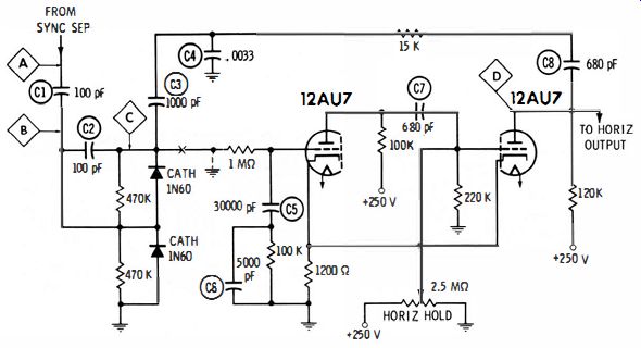
Fig. 6-1. Typical horizontal-oscillator and -afc configuration.
Normally, a waveform is found at point A, as shown in Fig. 6-2.
If the waveform at point A is absent or seriously distorted, the trouble is due to a defect in the sync separator, and not in the afc circuit. But if the sync separator is supplying a normal signal, check next at point B. It might be expected that the same waveform would be found here as at point A, but this is not the case. The reactance of the 100-pF coupling capacitor causes the waveshape to be different because it becomes mixed to some extent, with a sawtooth component from the horizontal oscillator (Fig. 6-3). The same waveform appears at points B and A only when the oscillator is inoperative.

Fig. 6-2. Normal input waveform obtained from the sync separator.
Fig. 6-3. Normal waveform at the output end of the coupling capacitor.
The sawtooth waveform from the horizontal oscillator (Fig. 6-4) enters the afc circuit at point C in Fig. 6-1. But suppose that capacitor C2 becomes leaky. The waveform then does not change in amplitude appreciably, but it becomes distorted as seen in Fig. 6-5. Horizontal locking is unstable under this condition. When waveform tests throw suspicion on a circuit, measure the dc voltages and resistances. Test the capacitors on a capacitor checker, or by substitution. Note in Fig. 6- 1 that the IN60 afc diodes may become defective and cause waveform changes. The diodes can be checked for front-to-back ratio with an ohmmeter or by substitution.

Fig. 6-4. Normal sawtooth waveform from horizontal-oscillator circuit.
Fig. 6.5. Waveform from horizontal-oscillator circuit when coupling capacitor
is leaky.
The afc circuit is basically a waveform comparison configuration.
The incoming sync pulses are mixed with a sawtooth wave from the oscillator. The mixed waveform is fed to the afc diodes and rectified.
This rectified de voltage is fed to the grid of the first tube in the multivibrator (oscillator) circuit. When this dc bias voltage is positive, the oscillator speeds up; when it is negative, the oscillator slows down.
The polarity of the dc output voltage from the afc diodes depends on the phase of the sawtooth wave with respect to the sync pulses.
When the pulses ride on top of the sawtooth wave, the mixed waveform has a high peak-to-peak voltage. When they ride part way down on the sawtooth wave, the mixed waveform has a lower peak-to-peak voltage. If a change in oscillator frequency (pulling) causes the sync pulses to ride lower on the sawtooth in one diode circuit, the opposite will occur for the other diode circuit. The dc output from the afc diodes will swing positive or negative, depending on which way the oscillator is pulling-that is, on whether it is trying to run too fast or too slow.
Next, consider the solid-state horizontal afc, oscillator, and driver arrangement shown in Fig. 6-6. This is an example of a balanced type of afc circuit which is driven in push-pull from a sync phase inverter.
A comparison waveform from the collector of the driver transistor is fed through L17 and C39 to the center of the balanced-diode afc circuit. Note that C96, C38, R123, R124, C97, and C98 form a coupling, filtering, and antihunt network. An antihunt network provides a system input-output phase relation which prevents self-oscillation. The most informative test in case of picture trouble symptoms is to check the peak-to-peak voltages and shapes of the afc and oscillator waveforms. In case the oscillator is off-frequency and the horizontal-hold control is out of range, it is helpful to note whether the oscillator is running too fast or too slow. This observation serves to eliminate particular components from suspicion.
OSCILLATOR OR AFC TROUBLE?
Sometimes the receiver acts as if the oscillator were running so far off-frequency that the afc circuit cannot pull it into sync. A simple test can be made to determine whether the trouble is in the afc section or in the oscillator section. Disconnect the 1-MO isolating resistor as indicated at X in Fig. 6- 1, and ground the disconnected end of the resistor as indicated by the dotted-line connection. If the trouble is in the afc circuit, it will be possible to free-wheel the picture into horizontal sync (at least momentarily) by critical adjustment of the horizontal-hold control. If the picture cannot be framed, the trouble is in the oscillator circuit.
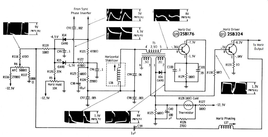
Fig. 6.6. This test is based on the principle that a normal oscillator operates
at about 15,750 Hz when the afc control voltage is zero. Hence, the control
voltage is set to zero by this test connection in order to see whether the
oscillator is capable of normal operation.
Although the circuit may look complex, it is merely an assembly of basically simple components. Therefore, the attack on a defective circuit is first of all a check of the individual components. Note here, too, that Ohm's law applies to reactance and to impedance in the same general manner as to resistance.
In case C1 is open, horizontal sync lock becomes extremely touchy.
The waveform at point B in Fig. 6- 1 does not exhibit a prominent sync-pulse component, but becomes a distorted sawtooth (Fig. 6-7). The sawtooth amplitude is less than that of the normal waveform, because the pulse component is missing.

Fig. 6-7. Waveform at point B when C1 is open.

Fig. 6-8. Waveform at point B when C2 is open.
When C2 is open, the waveform at point B becomes distorted as in Fig. 6-8. Although it might be expected that an open capacitor would decrease the waveform amplitude, that is not here. The diode response changes when the capacitor is open, and the waveform amplitude doubles (approximately). Stability of sync lock is not greatly affected on strong channels, but becomes unstable on weak-channel reception. Note that the waveform in Fig. 6-8, as in the case of previously illustrated waveforms, is taken with the picture framed in horizontal sync. This is important because the afc waveforms often become considerably changed and blurry if the picture is out of horizontal sync. When checking the waveforms, look at the picture occasionally to see whether or not it is still in sync. If not, adjust the horizontal-hold control as required, even if the adjustment is critical.
If C3 is open, the distorted waveform in Fig. 6-9 will appear at point B. The waveform has about double the normal amplitude, because of the increase in circuit impedance when C3 has no leading action.
The comparison waveform (oscillator sawtooth) is absent, and there fore the picture cannot be framed horizontally unless the I-M!). resistor is disconnected and grounded as shown by the dotted lines in Fig. 6- 1. Then the picture can be free-wheeled into frame by careful adjustment of the horizontal-hold control.
Again, if C4 is open, a distinctive distortion occurs in the waveform at point B, as shown in Fig. 6- 10. This distorted waveform has an amplitude several times higher than normal. When C4 is open, its normal attenuating or bypassing action is removed, and the sawtooth comparison wave increases substantially in amplitude.

Fig. 6-9. Waveform at point B when C3 is open.
Fig. 6-10. Waveform at point B when C4 is open.
SIGNAL-TRACING THE HORIZONTAL-OSCILLATOR SECTION
When the horizontal oscillator is inoperative, the screen is dark because there is no drive to the horizontal-output tube, and therefore no high voltage to the picture tube. Faults other than oscillation failure also cause a dark screen. For example, when C5 is open (Fig. 6- 1), the oscillator continues to function, but at an incorrect frequency. When the drive to the horizontal-output tube is considerably off-frequency, the high-voltage output falls so low that the screen becomes dark. Also, when CS is open, the grid-circuit impedance of the multivibrator input tube becomes very high, and spurious feedback occurs through the afc section into other receiver sections. This spurious feedback oscillation is audible and is called "squegging. " Squegging may also generate excessive spurious voltages which can break down some components.
All waveforms throughout the afc and oscillator section become highly distorted when the receiver is squegging. For example, Fig. 6-11 shows the distorted waveform at point B in Fig. 6-1. Its amplitude is considerably higher than that of the normal waveform. A similar trouble symptom occurs when C6 is open, but the squegging frequency is higher, and the screen does not go dark. The picture will not lock horizontally, of course. All waveforms in the horizontal section are distorted, and the waveform at point B appears as in Fig. 6-12. Its amplitude is considerably higher than normal.

Fig. 6-11. Waveform at point B when C5 is open.

Fig. 6-12. Waveform at point B when C6 is open.
The normal output waveform from the horizontal oscillator is seen in Fig. 6- 13. It is a peaked sawtooth waveform which drives the horizontal-output tube, and is checked at point D in Fig. 6- 1. Normal amplitude is 130 volts peak to peak. Reduced amplitude can be caused by either leakage or loss of capacitance in C7. If C7 is completely open, the oscillator will stop and the screen will be dark. The symptoms of leakage and low capacitance are shown in Fig. 6- 14. Fig. 6- 14A shows the distorted waveform which appears when C7 is quite leaky, and Fig. 6- 14B shows the effect of capacitance loss. Both waveforms appear at point D and both have more cycles than usual in the pattern when the scope deflection rate is set for 7875 Hz. More cycles appear than usual, because defects in C7 speed up the oscillator.
Although the horizontal-hold control is turned to the end of its range, the picture may be broken up into diagonal strips.
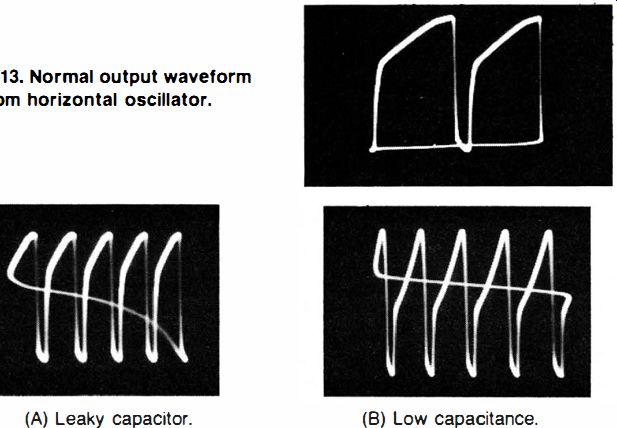
Fig. 6-13. Normal output waveform from horizontal Oscillator.

Fig. 6-14. Waveform symptoms of defects in C7 of Fig. 6-1. (A) Leaky capacitor.
(B) Low capacitance.
When C8 in Fig. 6- 1 is open, the picture-tube screen is dark. If C8 is leaky, the picture is present but horizontal sync is unstable. Waveform symptoms of these defects in C8 are shown in Fig. 6- 15. With C8 open (Fig. 6- 1 5A), the waveform at point D in Fig. 6- 1 is greatly reduced from its normal amplitude. Also, the oscillator runs too slowly, causing fewer cycles than usual to appear in the pattern. Low drive and low-frequency output combine to darken the picture-tube screen. If C8 is leaky, the oscillator can usually be adjusted to operate temporarily at 15,750 Hz, but continual drift necessitates frequent resetting of the horizontal-hold control. The waveform at point D (Fig. 6- 1 5B) is considerably distorted, but is almost normal in amplitude.
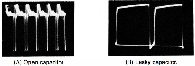
Fig. 6-15. Waveform symptoms of defects in C8 of Fig. 6-1. (A) Open capacitor.
(B) Leaky capacitor.
In addition to defective capacitors, off-value resistors or incorrect B+ supply voltage can cause trouble in horizontal-oscillator operation. Incorrect resistance values are easy to localize; therefore, the resulting waveform distortions are not shown here.
The foregoing discussion is concerned with a particular circuit configuration, but the general principles developed apply to other configurations. The essential procedure here is to check the observed waveshapes and amplitudes against the service data for the particular receiver, and, when deviations are noted, to analyze the pattern for the information which it contains.
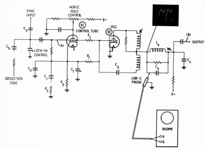
Fig. 6-16
SYNCHROGUIDE RINGING-COIL CHECK
Some horizontal-oscillator circuits, such as the Synchroguide configuration shown in Fig. 6- 16, have a ringing coil for stabilization of the oscillating frequency. The ringing coil is shown at La. To check the slug adjustment, connect a low-C probe as indicated, and observe the peaks of the waveform displayed on the scope screen. The pattern comprises a combination pulse and sine wave in which the positive peaks normally have the same horizontal level, as illustrated. If the pulse peaks are higher or lower than the sine-wave peaks, adjust the slug in the ringing coil as required.
A circuit defect is present when the peaks cannot be brought to the same height. The Synchroguide circuit uses a pulse-width method of generating control bias to the horizontal blocking oscillator. The control tube in Fig. 6- 16 is biased beyond cutoff. In other words, the grid is held highly negative with respect to the cathode (-14 volts is typical). A sawtooth voltage (Fig. 6- 17 A) is fed back from the blocking oscillator and combined with the sync pulse at the grid of the control tube. This waveform is seen at point A in Fig. 6- 16.
The positive peak of this combination waveform reduces the dc grid bias so that the control tube can conduct. Tube conduction generates a positive voltage in the cathode circuit (across Rg in Fig. 6- 16). This voltage reduces the negative grid bias at the oscillator, causing the oscillator to speed up. The value of the positive voltage which is thus generated depends on the phase relation between the sawtooth voltage and the pulse. Note in Fig. 6- 17 A how part of the pulse rides on top of the sawtooth, but also how part falls down on the steep portion of the sawtooth and does not contribute to the conduction interval.
If the pulse moves slightly to the left on the sawtooth, more of the pulse will appear on top, thus making the conduction interval longer.
In turn, more positive bias is generated and the oscillator speeds up.
The sawtooth then pulls to the right, part of the pulse is lost, and, effectively, the pulse width decreases. Equilibrium occurs at the width which keeps the sawtooth frequency exactly in step with the sync pulse.

Fig. 6-17. Normal Synchroguide waveforms. (A) At point A. (B) At point B
Component defects in either the control stage or the oscillator stage can cause the oscillator to pull excessively. The pulse width is narrower or wider than normal, causing inability to bring the peaks of the waveform in Fig. 6- 16 to the same level. Leaky capacitors are a common cause of this difficulty. The leakage changes the normal dc voltage distribution in the system, forcing the control bias from its normal range. Off-value resistors are less likely to cause pulling, but they should be checked in case the capacitors are good. The transformer is checked last, because it is an infrequent cause of operating trouble.
RINGING-COIL AND MULTIVIBRATOR CONFIGURATION
In older receivers you will often find the afc tube controlling a multivibrator sawtooth generator which includes a ringing coil, as shown in Fig. 6- 18. A comparison sawtooth from the sweep circuit (Fig. 6- 19) is fed into the afc diodes, where it is mixed with stripped sync from the phase inverter. The sawtooth has a normal l1mplitude of 15 volts peak to peak. If the sawtooth is weak or absent, the multivibrator frequency will be uncontrolled. Leakage or shorts in the .01-uF capacitor are likely to be the cause.
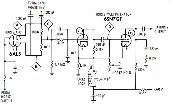
Fig. 6-18. Multivibrator with ringing coil.

Fig. 6-19. Comparison sawtooth from the sweep circuit.
Fig. 6-20. Mixed pulse and sawtooth waveform.
Positive sync pulses are coupled to the plate of one afc diode, and negative sync pulses are coupled to the cathode of the other diode.
Thus, both diodes are normally conducting simultaneously. At point A in Fig. 6- 18 a mixed pulse and sawtooth wave is seen, as in Fig. 6-20. The applied sawtooth voltage alternates above and below a zero level. Therefore, the mixed waveforms in the afc tube will make the two diodes conduct equally.
If the multivibrator tries to drift to a higher or lower frequency than the pulses, the feedback sawtooth will fall more or less out of step with the pulses. In turn, the afc diodes will develop a positive or negative dc voltage at point C, and the multivibrator will speed up or slow down. Hence, the dc voltage at point C rises and falls, or may change polarity when the oscillator attempts to drift either in a low- or high-frequency direction.
At point D in Fig. 6-18 another key troubleshooting waveform is observed. This is a combination pulse and sine-wave pattern, as in Fig. 6-21. The pulse is generated by multivibrator action during the horizontal-retrace interval. The sine wave is generated by shock excitation of the horizontal-locking (ringing) coil. If the pulse does not ride on top of the sine wave, adjust the slug in the ringing coil as required.
This is a stabilization adjustment. The sine wave causes multivibrator tube V2 to come out of cutoff rapidly instead of gradually. The noise immunity of the circuit is thus improved.
The RC network in the grid of V1 is a filtering and holding configuration. It provides a smooth dc control voltage to the grid, and it also delays passage of sudden input changes. As a result, noise pulses tend to average out and the oscillator is less likely to tear the picture when the noise level is high. Look for open capacitors if appreciable ac is found at the grid of V1.
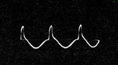
Fig. 6-21. Pulse and sine waveform.
CIRCUIT VARIATIONS
Although the end result is always the same in any afc-oscillator configuration, different manufacturers employ wide variations in circuitry. Do not attempt, therefore, to evaluate waveforms without reference to the service data for the particular chassis. It is practically impossible for even experienced technicians to inspect a new circuit and deduce the correct waveforms and peak-to-peak voltages. Commercial circuits are too complex for such deductions to be drawn with any reasonable accuracy.