AMAZON multi-meters discounts / AMAZON oscilloscope discounts
Many types of diagrams are needed to completely describe the operation and construction of electronic equipment. The most widely used, of course, is the schematic diagram-the subject of this guide. A schematic is usually all that is required for analyzing, explaining, and servicing most circuits. But as we shall see, it cannot convey all the information about a piece of equipment; other types of diagrams are needed as well.
In this section we will discuss each of the different types, pointing out their particular advantages and disadvantages.
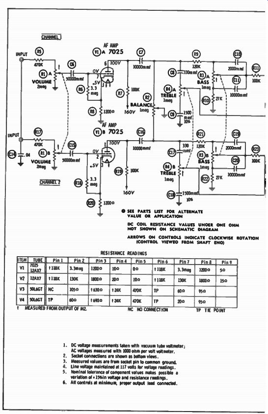
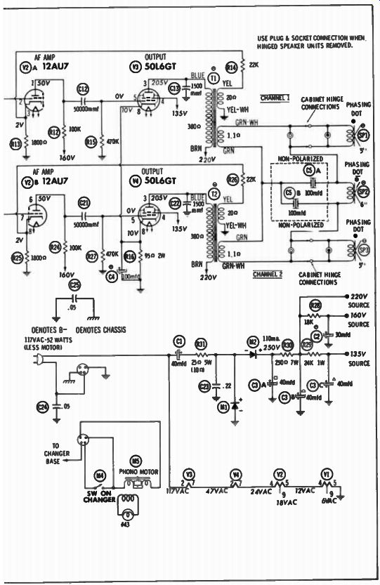
Fig. 1. Schematic of a typical stereo phono amplifier.
1. DC voltage measurements taken with vacuum tube voltmeter; AC voltages measured with 1000 ohm per volt voltmeter.
2. Socket connections are sham as bottom views.
3. Measured values are from socket pin to common ground.
4. Line voltage maintained at 117 volts for voltage readings.
5. Nominal tolerance of component values makes possible a variation of 1511e voltage and resistance readings.
6. All controls at minimum, proper output load connected.
SCHEMATIC DIAGRAMS
The first questions the layman or student may ask when confronted by a schematic are "Why use all of these symbols? Couldn't the same information be given without resorting to the use of sign language? Is this just a conspiracy among people in electronics to keep us from learning the art?" The answer to the last two questions, as you will see, is no.
Why Schematics and Symbols?
Symbols are used in electronic diagrams because experience has shown us they are the quickest and easiest way to convey the needed information. Simple symbols are a form of electronic shorthand. With them a circuit can be sketched in a short time; and because the symbols are standard, they can be easily interpreted by other persons.
Use of symbols, or "sign language," enables all the necessary circuit information to be given on a relatively small drawing. Such a drawing is much easier to follow, or "read," than either an illustration or a photograph of the actual assembly of parts. Imagine the problems involved in trying to represent and analyze electronic equipment and components from "true-to-life" drawings! In addition, a drawing of the outside does not show what is inside a tube or transmitter, for example.
If all the information contained in a schematic for even a simple radio were to be placed in written form, it would fill a book--yet, the schematic of the radio would easily fit on this page! No, schematics are not meant to keep you in the dark about electronics. What the blueprint is to the architect or machinist, and the formula is to the chemist, the schematic is to those working with electronics. If you are just starting in electronics, study this guide diligently. No matter what branch of this broad, fascinating field you eventually specialize in, a thorough knowledge of the symbols included in this guide must be acquired first.
Information Conveyed by Schematics
Fig. 1 shows the schematic of a typical amplifier used in a portable phonograph. Don't be concerned if it looks confusing to you now. In later sections each symbol will be explained in detail. For the present we are only interested in what a schematic looks like and the kind of information it conveys.
First of all, the schematic shows all the electrical components and how they are connected to make up the circuit. The value (size) or type of each component is given, along with the colors of transformer leads, the connections to each component, and other identifying marks.
A chart showing electrical measurements obtained at the various points, and the conditions under which they were taken, is also included in Fig. 1.
Component Identification
Another very important item included in Fig. 1 is a means of identifying each component. Notice the circled letter-and-number combinations beside each part. The letter signifies the type of component, and the number distinguishes it from all others of the same type. For instance, instead of saying "the 5,000-mmf capacitor connected between the volume control and pin 7 of the 7025 tube," we can merely say "C6." Other portions of the literature concerning a particular piece of equipment will also use these same letter--and number designations. For instance, C6 may appear in a parts list which gives the part numbers and specifications for each component, and also on a photo or drawing which shows its location. Thus, by using the same designation in all places to identify a component, there is less chance for an error to be made.
Unfortunately, all manufacturers do not designate a given component by the same code letters (or "call-outs" as they are sometimes called). However, they are fairly standard and usually on a few items will be different. The code letters used by Sams & Co., Inc., appear in Table 1-1. In later sections the code letters used by others will be given where they differ from the code letters that are used by Howard W. Sams & Co., Inc.
-----------
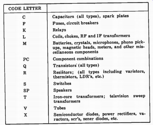
Table 1-1. Code Letter Designation Used by Howard W. Sams & Co., Inc.
CODE LETTER
Capacitors (all types), spark plates
Fuses, circuit breakers
Relays
Coils, chokes, RF and IF transformers
Batteries, crystals, microphones, phono pick ups, magnetic heads, meters, and other miscellaneous components
Component combinations; Transistors (all types)
Resistors; (all types including varistors, thermistors, LDR's, etc.)
Switches
Speakers
Iron-core transformers; television sweep transformers
Tubes
Semiconductor diodes, power rectifiers, varactors, scr's, zener diodes, etc.
------------
Symbol Variation
Like the code letters, the symbols used by different companies also differ. The symbols for each component will be discussed in the following sections, and where differences exist, the various ways of depicting a given item will be shown.
Organizations such as the Institute of Electrical and Electronic Engineers (IEEE) have adopted standard symbols which they hope the industry will use. Likewise, there are standards adopted by the American Standards Association and the military services, which fortunately, are identical.
Recently, the Electronic Industries Association (EIA) has been instrumental in coordinating the efforts of various groups aimed at standardization of symbols.
The symbols used throughout the world are fairly standard. Once the symbols given in this guide are mastered, you should have no problem understanding a schematic from anywhere-except of course, foreign terms will be used on it. The differences between two U.S. schematics may be greater than between a U.S. and a foreign schematic.
Fortunately, the differences in the symbol used by various companies to depict a component are not so great as in previous years. Differences still exist, however, so in the later sections of this guide, the symbols used by various companies will be shown. In general, the weight of a line or minor differences do not change the meaning of a symbol.
In fact, the symbol can be completely reversed; that is, two symbols can be the mirror image of each other and still have the same meaning.
Most of the differences in the symbols chosen stem from differences in the type of drafting and the method of laying out the circuit; they have no effect on the meaning. Schematics may be hand sketched, drawn with ink and a symbol guide, produced using preprinted symbols, or even prepared by a machine having a keyboard similar to that of a type setting machine. Therefore, minor differences are inevitable.
BLOCK DIAGRAMS
The block diagram (Fig. 2) is also often used in electronics. Even though it does not provide as much information as the schematic, it nevertheless is very useful because it is easier to interpret for certain limited purposes.
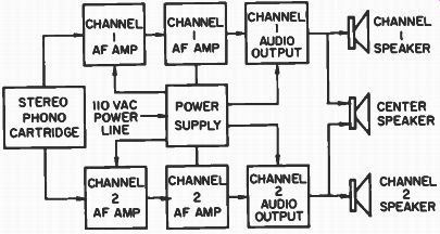
Fig. 2. Block diagram of the phono amplifier in Fig. 1.
The principal use of the block diagram is to show the overall operation of the circuit-in other words, the inter relationships of the various stages. Additional blocks will often be included to provide other information. The diagram in Fig. 2 is "read" by starting with the block farthest to the left, labeled "Stereo Phono Cartridge," then following the arrows through the two AF amplifiers, the audio-output tube, and ending at the speakers. Since this is a stereo amplifier, two arrows extend from the phono-cartridge block-one leading to the top row of blocks and the other to the bottom row. These two rows represent the amplifiers for the two channels of the stereo system. Notice that this unit has, in addition to a speaker for each individual channel, a center speaker to which the signals from both channels are fed. The block in the center, labeled "Power Supply," furnishes all the other blocks with the necessary power.
In summary, a block diagram shows the path of the signal through the circuit, and the function of each stage. It does not furnish any information about the type of connections or components; hence, it has only limited use. But for only a brief look at the over-all operation and functions of a unit, the block diagram is the simplest and easiest to follow.
CHASSIS-LAYOUT DIAGRAMS
A third type of diagram appears in Fig. 3. Often called a tube placement chart, it shows the physical locations of the major components. (Note: this is the same stereo phonograph shown in Figs. 1-1 and 1-2.) A placement chart is extremely useful for more complicated pieces of equipment such as television receivers. As more and more tubes and other components are added, the task of determining just which tube or transistor fulfills a given function becomes more difficult. With a diagram like the one in Fig. 3, locating a certain tube is greatly simplified. The dashed lines for the controls indicate they are located under the chassis.
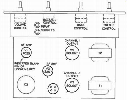
Fig. 3. Chassis-layout diagram for the phono amplifier in Fig. 1.
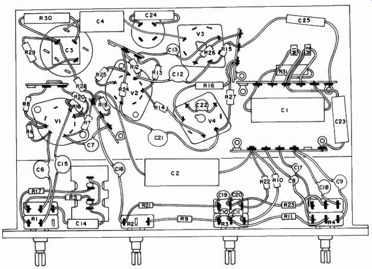
Fig. 4
Notice the short lines intersecting the circles representing tubes. All tubes have some method of orientation in the socket-either a blank space or a locating key on the base.
This short line indicates either the position of the blank space or the direction in which the locating key points on the socket. By noting the position of this line on the diagram, and by turning the tube so that its blank space or locating key is pointed in this direction, its insertion into the socket is made much easier-especially if the tube socket is hard to reach.
PHOTOS AND PICTORIAL DIAGRAMS
The schematic diagram has one important limitation--it does not show the actual physical location of the individual components. Even though it shows all electrical connections correctly, a particular part will often be located some distance away from its associated components on the chassis.
Such a part could be located by tracing through the circuit- but the easiest way is to use a pictorial diagram like the one shown in Fig. 4, or a photograph with each part labeled, as shown in Fig. 5. (Figs. 1-4 and 1-5 both illustrate the circuit in Fig. 1.)
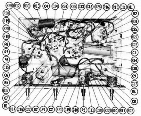
Fig. 5. Photo of underside of phono-amplifier chassis.
In the photograph, parts located beneath other components cannot be seen. In such a case the line pointing out the hidden component will stop on the object hiding it, and the arrow head will be omitted to signify that it is the part underneath.
The only disadvantage of the photograph is its inability to show connections as clearly as the pictorial diagram. But neither can show them as clearly as the schematic. Therefore, when the electrical connections are of primary interest, a schematic is used; but when only the physical location of a given part is desired, a pictorial or photograph is of greater value.
MECHANICAL DIAGRAMS
One important function ignored by the diagrams discussed previously is mechanical action or connections. Let us look at a few of the more common types of diagrams used for this purpose.
Dial-Cord Stringing
Replacing a dial cord on a receiver can be a most difficult and, in some instances, an impossible task without proper instruction. Fig. 6 shows a diagram prepared to provide the necessary information to make the job comparatively easy.
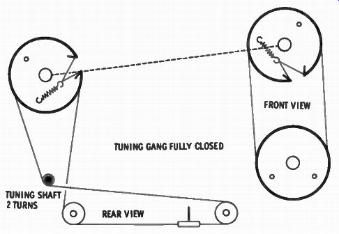
Fig. 6. A dial-cord stringing diagram.
TUNING GANG FULLY CLOSED TUNING SHAFT 2 TURNS
Without such help, hours might be spent trying to determine the correct method, especially for more complicated arrangements.
"Exploded" Views
For certain pieces of electrical and electronic equipment the operation of which is largely mechanical (such as record changers and tape recorders), the interrelationship between parts can best be shown on a diagram known as an "exploded" view. Fig. 7 shows such a diagram of the 45-rpm spindle used with the amplifier previously discussed. Note that each part is "exploded" from its normal position. The relationship of each part with respect to all the others is maintained, however, and the dashed lines point to their correct position in the assembly. Each part is identified by a circled number. By referring to this number in the parts list, the name and description of the item, as well as the manufacturer's part number (if a replacement must be ordered), can be determined.
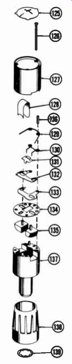
Fig. 7. Exploded view of the 45-rpm spindle for a record changer.
REVIEW OF FUNDAMENTALS
While this guide is not intended as a text on basic electronic theory, a brief review of fundamental principles may be of value, especially in understanding some of the terms used in the sections to follow.
Electron Theory
All matter is composed of atoms, made up of a nucleus surrounded by small particles rotating in orbits. These particles, called electrons, possess a unit negative charge which is matched in the core of the atom by an equal but opposite positive charge. One of the fundamental laws of nature is that unlike charges attract (like charges repel). Therefore, the electron is attracted to the nucleus, and only the centrifugal force present due to its orbital speed prevents the electron from joining the nucleus.
This attraction between the core of the atom and the orbiting electron is so great that to separate them requires a certain force. Electrons that have been freed will move away from any negative source and toward a positive source. This movement is known as an electron flow, or more commonly, an electric current, the basic unit of measurement of which is the ampere. The force causing this movement is known as a potential, or voltage, the volt being the basic measurement unit.
The atoms in some materials do not hold to their electrons so tightly as do the atoms in others. Such materials are said to be good conductors. If the electrons are more tightly held, then the material does not readily permit current flow and is said to be a good insulator.
(C) Pulsating. (A) Direct. (B) Alternating.
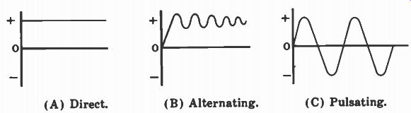
Fig. 8. Current waveforms.
Direct and Alternating Current
The voltage applied to a circuit to cause electron flow can be of many different forms. The simplest is that obtained from a battery. Here, the battery will present to the circuit a constant voltage, negative at one point and positive at the other. The electrons will therefore move from the negative to the positive potential; the quantity is determined by the amount of voltage applied and by the degree of opposition offered by the atoms in freeing the electrons. This type of flow, which is constant in quantity, is called direct current (DC) since the movement is in only one direction. Fig. 8A shows the waveform of such a current. In this graph the distance between the line representing the voltage and the line at the center representing zero voltage signifies the amount of voltage. The fact that this is a straight line shows that it is a constant, DC voltage.
If the applied voltage is caused to change periodically, from a varying positive to a varying negative potential, then the flow is known as alternating current (AC), shown graphically in Fig. 8B. The most common example is the familiar AC power found in most of today's homes. Here, the voltage reverses itself sixty times each second, causing current to flow first in one direction and then in the other.
There is another type of current, called pulsating direct current, often encountered in electronics. It occurs when the voltage varies in value but does not reverse itself. Examination of Fig. 8C will reveal that pulsating DC is actually a composite of an AC and a DC waveform, with the AC riding "piggyback" on the DC. Although an attempt has been made to present the material in this guide as clearly as possible, some of the terms may not be familiar to the reader. It is suggested that a basic electronics text be consulted in such instances.
QUESTIONS
1. What is a schematic?
2. How are the individual components on a schematic identified ?
3. What information does a block diagram convey?
4. What does a pictorial diagram or picture show that a schematic cannot?
5. What are the advantages of a picture over a pictorial diagram?
6. Why are schematics used ?
7. How are record-changer mechanisms usually shown in service literature?
8. What does a chassis-layout diagram show?
9. Name two types of mechanical diagrams.
10. What is the most popular type of electronic diagram?