AMAZON multi-meters discounts / AMAZON oscilloscope discounts
The resistor is probably the most common of all electronic components. Every radio, television, or other piece of electronic equipment will contain several such units.
WHAT IS A RESISTOR?
In electronic circuits, resistors perform exactly the function their name implies--they resist, or oppose, the flow of electrons. In other words, a resistor might be said to intro duce electrical friction. Every electrical component contains a certain amount of resistance, even a piece of ordinary wire.
But to obtain the amount of resistance provided by just one resistor might require many feet, or even miles, of wire. By using resistors, however, practically any amount of resistance can be contained in a small, compact unit.
Resistor Ratings
Two types of ratings, or values, are specified for a resistor.
The first is the electrical value--how much resistance it will introduce into the circuit. This value is given in ohms, the unit of resistance measurement. Thus, if a resistor has a value of 1,000 ohms it will introduce an electrical opposition of 1,000 units to the flow of electrons in a circuit.
This opposition reduces the amount of current flow in a given circuit. By proper selection of resistor value it is possible to obtain the exact amount of current required. Also, when current flows through a resistor a voltage is developed across it. This means that the voltage at one end of a resistor will be lower than at the other end by an amount proportional to the current flow through it. Mathematically, this is expressed as:
E=IxR
where, E is the voltage in volts, I is the current in amperes, R is the resistance in ohms.
Thus, the two most important functions of a resistor are: (1) to limit current flow, and (2) to provide a voltage difference.
The second value given in rating a resistor is the wattage--how much current can flow through it without causing damage. The unit of measurement is the watt, and in general, the larger the physical size of the resistor the higher its watt age rating will be. Common ratings are 1/4, 1/2, 1, 2, and 5 watts or more. Regardless of this wattage rating, however, the resistance of the unit does not change. Thus, a 1/2-watt resistor could be replaced by a 1-watt or even a 5-watt unit.
If, however, a 1-watt resistor was replaced by a 1/2-watt unit, the latter might burn out.
Abbreviations and symbols are often used in designating resistor values. For example, the Greek letter omega (a) is usually employed in the place of the word "ohm." Thus, instead of writing out 100 ohms, it is usually written as 100-ohm.
The letter K is used to designate 1,000 and meg or megohm stands for "one million ohms." The K is sometimes followed by the n sign-at other times it is understood and hence omitted. Thus 100,000 ohms, 100Kn, and 100K all mean the same. Watts is usually indicated by the capital letter W. For instance, 1W signifies a 1-watt unit.
FIXED RESISTORS
The fixed resistor is the simplest type. "Fixed" means the unit is constructed in such a way that its ohmic value cannot be varied. Fig. 1 shows some examples of this type, each having a certain value determined by the composition and amount of the material from which it is made.
Many fixed resistors are made of a carbon composition- hence the name carbon resistor. Others, especially those for high-wattage applications, use a special high-resistance wire wound on a ceramic or other insulating core. This assembly is then covered with a vitreous-enamel protective coating. A cutaway view of this type is shown in Fig. 2.
Another type of resistor developed for certain applications is the metallized unit. It is constructed by depositing a thin coating of a resistive material onto a glass rod.
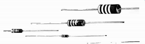
Fig. 1. An assortment of carbon resistors. Courtesy Ohmite Manufacturing
Co.
A fixed resistor is usually marked in some way to show the value of the unit. This is most often done by a system of color coding. Fig. 3 shows the code used for carbon resistors-the most common method shown in Fig 2-3A and the older methods in Figs. 2-3B, C, and D. In the first method the two bands nearest the end designate the first two figures of the ohmic value, and the third band the number of zeros to be added to arrive at the correct value.
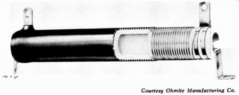
Fig. 2. Construction of a wirewound resistor. Courtesy Ohmite Manufacturing
Co.
Thus, a resistor having a yellow, violet, and red band has a value of 4,700 ohms. If a fourth band is present, it will signify how close the resistance is to the indicated value. This is known as the tolerance. It is impossible to make each resistor to have the exact resistance indicated by its color bands, so certain standard values have been adopted. All resistors which fall within the required percentage of this standard are coded with this value. If no fourth band is present, the resistor is within 20% of the indicated value. A silver band designates 10% , and a gold band, 5% tolerance. Other tolerances are given in Fig. 3.
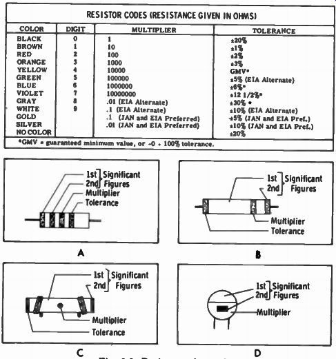

Fig. 3. Resistor color codes. RESISTOR CODES (RESISTANCE GIVEN IN OHMS)
Other resistors, especially the wirewound type, will have the value stamped on the side. The wattage rating will often be included also. Some of the newer resistors are so tiny there is no room for a complete color code. In resistors of this type a special code must be devised; for example, a single red dot might designate a 2,200-ohm resistor.
The schematic symbols for designating fixed resistors are shown in Fig. 4. The symbol at A is the most common- those at B and C will seldom be encountered. When the symbol at B is used, the value of the resistor will usually be placed inside the box. It is more popular in foreign schematics.
Like the resistance symbol, the code letter used to designate a resistance is also more standardized than most of the others. All American manufacturers designate a fixed resistor by the letter R.
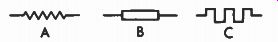
Fig. 4. Fixed-resistor symbols.
TAPPED AND ADJUSTABLE RESISTORS
A fixed resistor will sometimes have a tap or connection at some point along the resistance material. Fig. 5 shows the symbols used for such a unit. The symbol at A is used almost exclusively and is the same as for a fixed resistor except for the dot and the line connected to the zigzag portion. If there are two taps, another line and dot are added as shown at B.
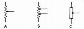
Fig. 5. Tapped-resistor symbols.
(The dot is sometimes omitted and the line connected directly to the symbol.) The resistance value of the entire unit, as well as the value at the tapped point, is given for this type of resistor. The symbol at C in Fig. 5 is seldom used.
Most tapped resistors are wirewound units with a separate terminal for each tap. In some units the tap is made adjust able by making it in the form of a band around the resistor.
The resistance wire is left exposed along one side of the unit and this band makes contact at the desired point. It is then secured by tightening a screw. Fig. 6 shows an assortment of wirewound resistors, many having taps. Those at the right in the illustration are adjustable units.
The same symbols shown in Fig. 5 are sometimes used to designate these types of adjustable resistors. The dot, however, is usually replaced by an arrowhead, as shown in Fig. 7. Like the fixed resistor, R is the code letter always used for both tapped and adjustable resistors.
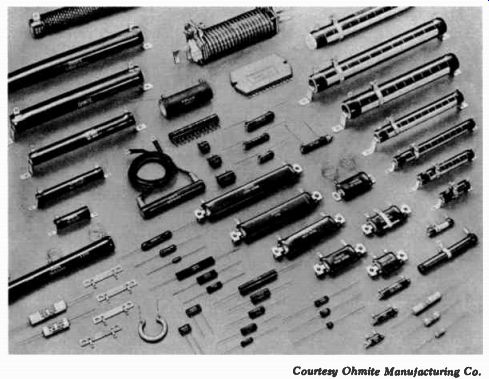
Fig. 6. A wide variety of wirewound resistors. Courtesy Ohmite Manufacturing
Co.
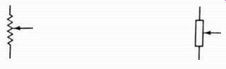
Fig. 7. Symbols sometimes used for adjustable resistors.
VARIABLE RESISTORS
A resistor which can be continuously varied in value is often needed. The volume control is one of the most common examples. Another use for such a resistor is in lighting circuits to vary the light intensity. For the volume control, the variable resistance is usually called a potentiometer, while for the lighting circuit it is usually called a rheostat.
Both potentiometers and rheostats are very similar in construction, consisting of a resistance element (usually arranged in a circle) and a sliding contact as shown in Fig. 8.
As the contact moves along the element the amount of resistance between it and the end of the element changes.
Rheostats are nearly always wirewound, while the element in potentiometers may be either carbon or wire. A potentiometer always has three terminals, one at each end of the resistance element and one for the sliding contact. A rheostat, however, may have only two-one at one end of the element and one for the sliding contact.
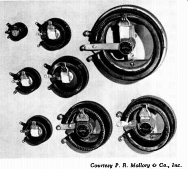
Fig. 8. An assortment of various size rheostats. Courtesy P. R. Mallory
Co., Inc.
The most common variable-resistor symbols are those labeled A and B in Fig. 9. These are alike with the exception that no connection is shown at one end in B. This does not necessarily mean the unit has only two connections. If the third terminal is not used--as is often the case--it is not shown. The symbol at C also designates either a rheostat or potentiometer with only two terminals used. Here, the arrow through the symbol signifies it is adjustable. Five other variations are shown at D, E, F, G, and H. The symbol at E represents a preset adjustment (usually a screwdriver adjustment). Quite often, however, the other symbols are used to represent this type of variable resistor.
The symbol at I signifies a potentiometer that has a tap to provide an additional fixed connection. Some units are made in such a way that the sliding contact will not move beyond a certain point on the element. This always leaves some resistance between the arm and one end of the potentiometer. The symbol for this type is shown at J; the line drawn across the symbol indicates the limit to which the movable contact will travel.
The value of a variable resistance may not always be stamped on the unit. The manufacturer's part number is often the only information given. To find the value, refer to the schematic, parts list, or manufacturer's catalog.
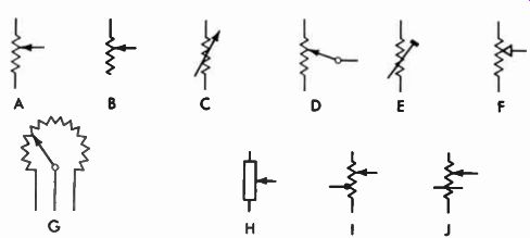
Fig. 9. Potentiometer and rheostat symbols.
The most popular code letter for designating a variable resistor is R. Some manufacturers, however, prefer the letter P (for potentiometer) or VR (for variable resistor).
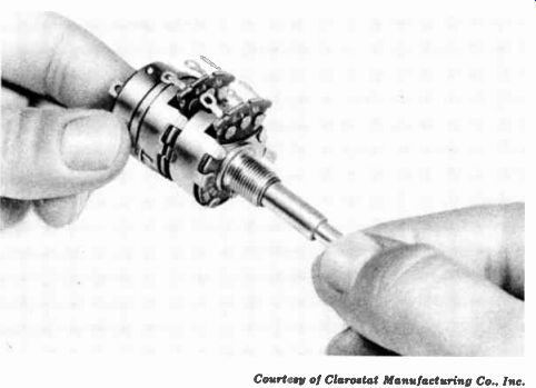
Fig. 10. A two-section potentiometer with an on-off switch mounted on the
rear. Courtesy of Clarostat Manufacturing Co., Inc.
Two potentiometers are sometimes constructed in one assembly, one unit being mounted behind the other. The shaft for one is hollow, allowing the shaft of the other unit to pass through it. This arrangement is quite common for certain TV controls; the operation is the same as for two separate units. The same code letter and number will often designate both units, with an A and B added to distinguish between them-such as R1A and R1B. A switch may also be included on the back of potentiometers, as shown in Fig. 10. The same shaft which varies the resistance also actuates the switch. Electrically, however, there is no connection between the two.
SPECIAL RESISTORS
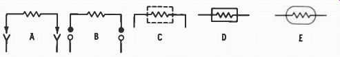
Fig. 11. Fusible-resistor symbols.
One of the most common of what might be called a "special" resistor is the fusible type. As its name implies, it acts as a fuse, opening the circuit if the current exceeds a certain limit. This protects expensive components against damage, and only a relatively inexpensive resistor must be replaced. Such units often are made to plug into a socket on the chassis, making replacement as simple as changing a tube. The symbols for such components are given in Fig. 11. Notice that the familiar resistor symbol is still used, but with the plug-in arrangement indicated by an arrowhead or other appropriate designation. The fact that the unit is fusible is usually indicated by a notation near the symbol.
Occasionally the conventional fuse symbol (see Section 8) is used for a fusible resistor.
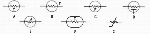
Fig. 12. Temperature-compensating resistor symbols.
Often there is a need for a special type of resistor which will vary in value when the conditions surrounding it or conditions in the circuit change. Many of these units are actually semiconductor devices (to be discussed in a later section) ; however, since they are used in a circuit to supply resistance, they will be given in this section.
As the temperature of a common resistor rises because of heat from surrounding components or from its own internal electron flow, the resistance of the resistor increases. To forestall this change, the composition of the resistor is altered to cause its resistance to decrease when the tempera ture increases. In fact, the change in resistance can be made to either increase, decrease, or remain constant regardless of the direction of temperature change (within limits, of course). These units are known as temperature-compensating resistors, thermistors, or thermal resistors (Fig. 12). If the resistance decreases as the temperature rises, they are said to have a negative temperature coefficient (NTC) ; if it increases, they have a positive temperature coefficient (PTC). The abbreviation signifying the type is usually placed beside the symbol.
Resistors are also available which vary in value according to the current through them or the voltage present in the circuit. Others vary in value when light strikes them. Often the same symbol shown at A in Fig. 12 is used for these resistors except the letter designating the type is changed to V for voltage, I for current, or L or X for light. Other manufacturers use different symbols, however. In Fig. 13, symbols A through I are for voltage-dependent resistors; those in J through It are for light-dependent resistors.
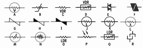
Fig. 13. Voltage- and light-dependent resistor symbols.
The letter R is usually employed as the code letter for voltage-, current-, temperature-, or light-dependent resistors.
However, RT may be used for temperature-dependent resistors and RV for voltage-dependent resistors. In addition, D is sometimes used as the code letter for semiconductor type resistors.
QUESTIONS
1. What is the unit of measurement for the amount of resistance?
2. What are the two main purposes of resistors?
3. What is resistance?
4. What Greek letter is used as the symbol for ohm?
5. What is a potentiometer?
6. What code letter is used for resistors?
7. What is the value of a resistor with red, violet, and orange bands?
8. What is a negative temperature-coefficient resistor?
9. Draw the symbol for a fixed resistor.
10. Draw the symbol for a tapped potentiometer.