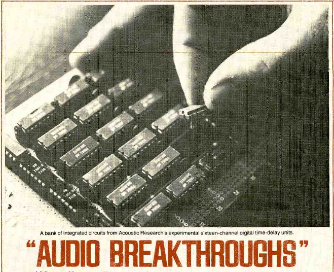
---- A bank of integrated circuits from Acoustic Research's experimental sixteen-channel digital time-delay units.
What effects will new technology have on the future of hi fi?
By Peter Sutheim
IN many manufacturing fields, the actual importance of a new technique, technology, or device can sometimes he established only by the test of time.
If a new product category, circuit, or solid-state device achieves rapid, wide spread use in the electronics area, it most probably is a genuine advance--if sometimes only because it produces the same results at lower cost or with greater reliability. Though it is obviously much too soon to pass judgment on the ultimate significance of many of the most recent audio "breakthroughs," they bear examination and merit under standing to the extent that they are al ready affecting the design of present day products.
Shoe mere common sense, even assisted by a technical background, can provide only very sketchy guidance through the new technology's tangle of claims and counterclaims., we have asked Peter Sutheim, a gentleman with a good grasp of these matters, to discuss some of the new devices-and some of the new wrinkles in old ones that have caught his eye recently. It is certain that, by the time his observations reach the reader's hands, there will be at least one brand-new device or technique that we will wish we had included. But, not unlike Alice and the White Queen in Wonderland, we in the land of audio have to run as fast as we can simply to maintain our level of understanding. And so, panting, we apologize for the possible omission of some recent development of merit, pleading lack of insight, foresight, and/or space.
"High-Class" Amplifier Designs Most audiophiles are accustomed to considering speaker efficiency, but they seldom think about how wasteful or thrifty their amplifiers may be. Yet, as amplifier power ratings climb ever higher, designers are concerning them selves with efficiency-not because of energy shortages, but because whatever power the amplifier draws from the a.c. line that is not turned into audio-power output is turned into heat.
A typical component amplifier de signed to operate in " Class AB" (the usual mode) is quite efficient when delivering its maximum power output, but in practice a music amplifier is hardly ever called upon to do that. At average power outputs of one-tenth to one-half of maximum (typical when playing mu sic) the amplifier is considerably less efficient and may actually heat up more than it does at maximum output. The amplifier's power supply must of course be designed to provide even that part of the power that is wasted, which means heavier, bulkier, and more costly parts. And the finned heat radiators for the output transistors must be large enough to radiate away the waste heat before destructive overheating occurs.
The more powerful the amplifier, the greater the cost advantage of a slight increase in efficiency. A truly significant increase in efficiency would mean a high-power amplifier that is smaller, lighter, and perhaps somewhat cheaper than its less efficient, hotter competition.
One radical approach to higher efficiency has been considered for a dozen years or more, but it has only recently appeared in a few commercial products. Referred to as "Class D," this technique uses the output transistors as switches rather than as "linear" amplifiers. The input signal to the amplifier is used to vary some aspect let's say the width-of a continuing series of pulses generated by a circuit in-the amplifier. The nature of the pulses is such that, regardless of their width, they cause the output transistors to be either fully conducting or fully nonconducting. Either way, the output transistors dissipate much less power than they do in the "in-between" states nor mal to operation as conventional linear amplifiers.
In order to insure that it won't make trouble, the pulse train has to have a rate, or frequency, at least ten times higher than the highest audio frequency to be amplified. This very high frequency permits the pulses to be filtered at the output, essentially causing them to disappear and restoring the audio signal. Despite the chopped, "on-off" nature of the process, the result can be a very precise (low-distortion) amplification of the input signal. And an efficiency of 90 percent or better at all power levels can be achieved.
A somewhat less dramatic attack on the efficiency problem has been mount ed by Hitachi in several of their products. Called "Class G," it uses fairly conventional solid-state power-amplifier design (as contrasted with switching amplifiers, anyway), but with an important difference: instead of the conventional paired set of output transistors for each channel, Hitachi has two sets of transistors per output channel. The "lower" or "inner" pair operates approximately like any other low-power Class AB output fed from a moderate supply voltage. When a high-amplitude signal peak comes along, the higher-power transistors are turned on, fed from a power-supply voltage more than twice as high. In effect, Hitachi has an amplifier that operates as a low-power unit (with its low current drain) until high power is required--at which time the high-power section is switched on.
A related development is Soundcraftsmen's recently announced "Class H" amplifier. Again, the approach is to use two different power supplies-in this case without separate sets of output transistors. The output transistors are operated from a relatively low-voltage power supply most of the time, but when strong musical peaks are encountered, the other, higher-voltage supply (nominally one and one-half times the voltage of the low-voltage supply) is brought into action.
The higher-power supply voltage is also controlled by the level of the in coming audio signal.
TECHNICS has recently come up with a somewhat similar design which they call "Class A Plus." It, too, involves a power-supply voltage that is controlled by the audio signal, but there's only one supply and the action takes place continuously rather than on a "thresh old" basis as it does in the Soundcraftsmen unit. The Technics amplifier utilizes a Class-A output stage, the varying voltage supply for it being provided by another independent amplifier whose output is controlled by the audio signal. In this way, according to Technics, the linearity advantages of the Class-A design are realized with a vast improvement in efficiency over the conventional Class-A design.
-----------
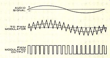
In Class-D amplification, a triangle wave is used to "encode" the audio signal into pulse-width-modulated form. The width of the pulses corresponds to the original audio-signal waveform's amplitude and polarity, the widest representing the, most positive part of the original wave, the thinnest representing the most negative. The "zero-crossing" part of the waveform is represented by a pulse of "average" width-which also appears when there is no audio signal present in the circuit. Reconverting the pulse-width-modulated/encoded signal into audio is a relatively simple process: a low-pass filter strips away the high-frequency triangle-wave rate and leaves the original audio waveform.
-------
"Even relatively efficient speakers convert about 95 per cent of the audio power ... into heat."
While the attention being paid to efficiency is commendable and would probably have come about sooner or later anyway, it was stimulated by the Federal Trade Commission's ruling on amplifier-power ratings, according to which an amplifier must be "preconditioned" before test by being run for one hour at one-third its rated operating power. The one-third level happens to be very nearly the most inefficient operating point for a Class-AB design, no matter whose product it is, and the amount of heat that must be dissipated in even a relatively modest amplifier is enormous. This requires notably larger heat sinks, and of course a heftier power supply to cover all that waste which in turn increases the bulk, weight, and cost of the amplifier with little or no audible benefit. The more efficient the output stage for a given power-output rating, the less need for excess capability in power supplies and heat radiators. It is necessary to keep in mind that efficiency and sound quality are not necessarily related. How good these designs sound is still deter mined by the care and judgment exercised in the engineering and not by any magic associated with a glamorous "new circuit." Carbon Fibers The key to much good design in the field of transducers (devices such as speakers and phono cartridges that change energy from one form to another) is to eliminate or minimize resonances. Musical instruments derive much of their special tonal qualities from resonances, but with audio equipment these have to be controlled to pre vent undue emphasis of frequencies that would result in coloration (distortion) of the reproduced sound.
Recently, that most astonishing and ubiquitous of elements, carbon, has been combined with paper pulp to pro duce woofer cones of great stiffness and high internal damping. The last fac tor is quite important, since it minimizes the tendency of a substance to vibrate or "ring" when excited. What is actually used is carbon fiber, one crystalline form of the element (graph ite and diamond are others). The car bon fiber, made by carbonizing poly-acrylic fiber at high temperatures, is mixed with the paper pulp in an amount up to 30 per cent of the total weight.
The practical effect of this compound material is to make a woofer cone that is less prone to breakup, ringing, and stored-energy problems.
Carbon fiber has also been applied in tone-arm design, where it is used as part of the structural material for the tone-arm tube. Here the purpose is to raise the frequency and to reduce the intensity of certain inevitable resonances in the arm assembly in order to make them less audible. The intended result is, again, less coloration of the reproduced sound.
High-polymer Molecular Film
Although speakers and headphones made with high-polymer molecular (HPM) film seem to resemble electro static designs, technically they are more closely related to the piezoelectric principle. As in electrostatic drivers, the element in the HPM device that actually moves the air to produce sound is a thin (about 1.2 mils thick) plastic film curved into a cylinder or hemi cylinder that radiates sound energy uniformly from its entire outer surface.
The film's vibrating motion is produced by a molecular structure that literally expands and contracts in accordance with the applied audio-signal voltage.
-----------------
THE CLASS STRUGGLE AMONG AMPLIFIERS
RECENT developments by Hitachi, Soundcraftsmen, and Technics, among others, have caused the notion of amplifier "class" to receive renewed competitive attention from amplifier designers. What is meant by the "class" of an amplifier? A good in-depth description can be found in Julian Hirsch's "Technical Talk" in the January 1977 issue, but here's what it means in brief:
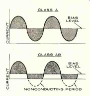
An amplifier is labeled Class "A," "B," or "X" according to the way its output stage operates. Currently, there are three basic classes suitable for audio applications: A, AB, and B (other classes recently devised are D, G, and H). The Class-A design consists in its simplest form of a single output transistor through which a high biasing current flows at all times, whether or not a signal is being handled. It is a very low-distortion amplifier when designed properly.
However, its inefficiency becomes a problem when high powers (more than 20 watts or so) are required, be cause the inefficiency is expressed as heat-lots of it.
Class-B design involves two (sets of) output transistors arranged in a so-called "push-pull" configuration.
If the input to a Class-B amplifier is a sine wave, the positive half of the waveform is handled by one transistor (or a set of them) and the negative half by the other. The outputs of the two halves of the circuit are combined to give an amplified sine wave at the outputs. In effect, the bias cur rent flows through each half of the output stage only for the time that the output-stage half is required to handle its part of the signal. The Class-B amplifier is therefore considerably more efficient than the Class-A one.
The problem with Class-B design is that "crossover" distortion can occur where the positive and negative halves of the signal meet and one transistor shuts off before the other turns on. This causes a "glitch" or discontinuity in the "crossover" area between them. The solution ( Class AB) makes use of the same output configuration but is biased some where between A and B. This minimizes crossover distortion while pro viding much of the efficiency of a Class-B amplifier.
Amplifier designers are continually seeking ways to provide higher power with lower distortion and lower heat, and this search has brought us the most recent developments, Classes D, G, and H; see text for the details.
-------------------
The mechanism is quite simple, but the chemistry that produced it is extremely complex. Pioneer, the manufacturer principally identified with HPM film, describes the expansion-contraction motion as "breathing," as contrasted with a reciprocating (back-and-forth) action.
Does HPM technology provide a real improvement in reproduction com pared with conventional dome, cone, and other surface-driven reproducers? HPM techniques may produce new de signs that are measurably and audibly superior, or-just as important designs that are as good as anything else but cheaper to produce, in which case the lower cost of manufacture ought to result in more good, low-price speaker systems. Offsetting this is the fact that HPM speakers, like electro static units, require step-up transformers to raise the audio-signal voltage to an appropriate level, and of course the transformers raise the cost.
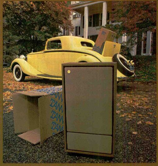
At this writing, the HPM principle is applied only in drivers operating at frequencies above about 2,000 Hz (but full-range HPM headphones are available). However, the HPM principle would seem to offer all the potential ad vantages of electrostatic speakers with out one of the significant disadvantages: the need for a very-high-voltage power supply. Given a sufficiently large radiating area, there seems to be no theoretical reason why we can't have full-range multiple-driver HPM speakers operating down to as low a frequency as desired. The next obvious step would be a four-foot-high (about a foot across) driver used as a low-frequency radiator. The mid- and high-frequency units would be stacked on top of this bass radiator, with their front edges pretty much lined up. Why not?
--------------
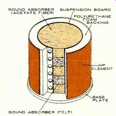
SOUND ABSORBER, SUSPENSION BOARD, (ACETATE FIBER), POLYURETHANE FOAM BACKING, HP ELEMENT, BASE PLATE, SOUND ABSORBER (FELT)
A cutaway view of an HPM tweeter shows the cylindrical HP element backed by sound-absorbing material. Sound moves radially outward.
-------------
Magnetic Fluid
Almost every moving system has resonances, the specific frequencies at which the system--or parts of it--prefers to vibrate. This is desirable in a bell, a tuning fork, or a musical instrument, where we expect to get a specific note in return for the energy we expend in blowing, stroking, striking, or plucking. Resonances can also be undesirable, in a speaker system for instance, which we expect to respond to a signal without adding any tonal contribution of its own. We also want a speaker to stop responding as soon as the input signal stops. Getting this performance from a speaker system requires careful attention to damping, which is simply the absorption of unwanted energy (it gets turned into heat). The devices called shock absorbers in cars are really dampers. They soak up and dissipate (as heat) the energy stored in the mass and springiness of the car's body and suspension. Without them, the car would continue to bounce indefinitely after hitting a bump in the road.
A woofer, tweeter, or mid-range can be damped in several ways, and many of these methods are used in various combinations in current designs. The load presented to a woofer cone by the air enclosed in the cabinet is one source of damping. The amplifier that drives the speaker also aids in damping. The mechanical design of the driver itself its cone material, suspension, and magnetic circuit-influences damping.
RECENTLY, another method of damping has come into fairly wide use: a ferromagnetic fluid is injected into the gap in which the voice coil moves. To make this comprehensible, check the drawing (at the top right of this page) that shows how the usual speaker mechanism works. A speaker driver operates under the same principle as an electric motor. A powerful, steady magnetic field is created in a circular gap by a permanent magnet. Suspend ed in this gap-without touching the magnetic poles-is a coil of wire called the voice coil. One end of the voice coil is rigidly cemented to the diaphragm (usually a cone or a dome). When an audio signal is applied to the voice coil from the amplifier's output, a varying magnetic field is created around the coil, which interacts with the steady permanent-magnet field to cause the coil to vibrate in and out of the gap, moving the cone or dome also, and it is this vibrating diaphragm that produces sound waves.
------------

CONE, VOICE COIL, FLEXIBLE SURROUND, SPIDER, VOICE COIL, MAGNETIC FLUID
Schematic view of standard dynamic driver. Special magnetic fluid applied to the voice-coil gap is held in place by the magnet's normal field.
-------------------
The narrow gap in which the voice coil has to vibrate back and forth suggests an opportunity for damping its motion. A moderately thick fluid (per haps of the consistency of motor oil) injected into the gap would do the trick, but keeping it in the gap would not be easy. However, a ferromagnetic fluid-one that behaves, in its liquid way, as iron does in response to a mag net-would stay in the gap because of the powerful magnetic field there.
If the ferrofluid can also retain its properties at high temperatures, it can benefit the speaker driver in another way: helping to draw waste heat out of the voice coil and into the surrounding magnet structure. Even relatively efficient speakers convert about 95 percent of the audio power they receive from the amplifier into heat. And considering the power available from to day's amplifiers, keeping the voice coil cool is a real problem. The air flow in the voice-coil gap helps some, but a suitable ferrofluid can improve heat transfer by as much as three times. As of this writing, the cost of ferromagnetic fluids is quite high. However, many speaker manufacturers have discovered that a little drop will do the job.
Phase-coherent Speaker Systems
Both "phase-coherent" and "time-compensated" are terms (there are others) that describe a speaker that has been electrically and physically de signed with the intention of permitting all the frequencies in the sound it re produces to arrive at your ear in the same time order (in addition to the same strength) in which they occurred in the original sound, the idea being that such a phase-accurate or linear-phase speaker is going to be more true to the original program than a speaker which is designed according to conventional principles.
Most speakers are not phase-accurate, chiefly because of the general practice of using an assortment of drivers each designed to cover a particular part of the audio-frequency range. It is usually not the drivers themselves that create the phase shifts, but rather how they are interconnected and installed that creates problems. These are of two kinds: one resulting from the fact that the drivers must necessarily be spaced apart, creating a difference in path length (to the listener) for sounds emerging from the two or more units;
the other resulting from the need to divide (cross over) the audio spectrum electrically into two or more frequency bands, sending to each driver only the band it is designed to reproduce. Since sound travels at a specific speed in air, a difference in sound-path length for the woofer, mid-range, and tweeter can result in different "arrival" times for different frequency components.
One thing the designer can do to avoid this is to position the drivers in such a way as to equalize the sound path lengths. This means taking into ac count the fact that the "virtual" depth of a woofer-the area of the cone where the sound really "comes from"--is different from that of a mid range or tweeter. Woofers are deep several inches in the case of typical 12-inch units. Mid-range units and tweeters are much shallower, and some may even protrude from the front plane of the baffle. Hence the appearance of stepped or "setback" cabinet designs, or designs with sloping fronts, to bring the woofer's specific acoustical "point of sonic origin" in line with those of the other drivers.
Unfortunately, appearance alone is no guarantee of anything. The design and selection of drivers, their spacing on the panel, the choice of crossover frequencies, the design of the crossover network itself, the acoustical proper ties of the enclosure--all these things profoundly influence the phase characteristics of a speaker system, and none of them can be evaluated by a simple visual examination.
The audible benefits of phase-coherent loudspeakers remain debatable, in part because so little available program material is itself phase-coherent. The multitrack techniques of today's re cording studios actually insure copious phase scrambling in the mixing con sole, and indeed even tape machines themselves introduce phase shift.
When and if recording studios ever get around to paying closer attention to phase factors, linear-phase loudspeakers may get a chance to prove their merits. This is not to say that many speakers designed to be phase-accurate (or whatever proprietary descriptive term the manufacturer chooses to use) today are not superb reproducers. The question being discussed is whether those speakers are excellent because they are phase-accurate or whether they happen to be excellent and are also phase-accurate. And, of course, we still have speakers that both test and sound excellent while paying no attention to phase linearity whatever.
Time-delay Devices It is certainly no secret that reproduced sound lacks much of the ambiance, the sense of "acoustic space," of live performances. It was recognition of this fact that ushered in an era of experimentation with stereophonic (from the Greek, meaning literally "solid sound") techniques which continues today. There are two basic approaches to the problem. The first is to attempt to re-create, more or less literally, the sound-space in which the original event took place by using stereo, binaural, and quadraphonic recording techniques. The second is to attempt to generate, by various means, some sort of plausible sound-space. Into this second category fall the electronic time-delay and reverberation devices and the various quadraphonic-ambiance synthesizers that work with the "difference signals" that are embodied in al most all stereo recordings. The difference signal contains random phase in formation that, when fed to the rear channel(s), can help provide a hall-sound illusion. More complicated synthesizers (usually part of a quadraphonic decoder) manipulate the difference signal electronically, sometimes with quite spectacular pseudo-quad results.
Since sound travels in air at a rate of about 1.1 feet in a thousandth of a second (or 1,100 feet per second), an aver age living room will provide mostly "early" reflections of the reproduced program. While the more delayed re flections of the recording-location hall may in fact be recorded along with the music, just playing them back through the front stereo speakers does little to re-create the acoustic presence of the hall. Using a pair of rear speakers (with or without some sort of synthesizer or decoder) helps, but it is still less than convincing because of the short time delays encountered in a typical-size listening room.
The best type of device available for overcoming this problem is the electronic time-delay unit. When properly used, it can have the effect of "pushing back the walls" of the listening environment. And it isn't simply that the music is heard as though it were in a larger room; the musical performance sounds more like it is taking place with in the room rather than being somehow inappropriately overlaid on the room's acoustics.
At this time, there are three manufacturers with commercially available audiophile time-delay units: Audio Pulse, Bozak, and Sound Concepts.
There are several other hi-fi companies with units already designed waiting in the wings, cautiously trying to estimate the potential market for the product be fore they commit themselves. And, of course, there are numerous non-audiophile reverb devices designed for recording-studio use.
The time-delay units presently avail able operate either on the "digital" or "bucket-brigade" principle. A digital unit, such as the Audio Pulse Model One, converts the audio signal into a pulse train which carries all the audio information in binary digital form. Simply explained, this encoded form of the audio signal is moved successively from one electronic storage cell (called a "shift register") to another, virtually without deterioration. The delay depends simply on the number of shift registers the encoded signal is "load ed" into and out of. The Sound Concepts units use a "bucket-brigade" circuit that passes a given signal step-by step through the circuits, achieving cumulative delays of 5 to 100 milliseconds. It samples, delays, and reassembles the audio signal itself instead of first converting it to digital form and then decoding it.
All these devices employ psychoacoustic principles "unnaturally" in the interest of more realistic reproduction.
Since we know to some degree what produces the subjective sensations of acoustic space, we can "pre-treat" the program material in such a way that the ear-brain system has difficulty differentiating between the illusion of acoustic space and its reality. Though it is possible at times to fool the ear and brain into thinking that a reproduced sound is the "original," the illusion remains rare and difficult to achieve.
Crystal Control
Even the seemingly simple and un glamorous task of making a record rotate at a precise and unwavering speed has received a lot of engineering attention, leading to the most recent development in turntable drives: the quartz-crystal-controlled , phase-locked-loop servomotor. Its basic element, the servomotor, is not new. Servo techniques have been used in industrial and military applications for decades. And their governing principle, negative feedback, has likewise been used in amplifiers for decades, Conceptually, the idea is simple. The turntable platter is driven by an electric motor whose speed can be made to vary by changing either the voltage or the frequency supplied to it. The mo tor's basic speed is determined in a rough way by appropriate design. Then a means of sensing the motor's (or the platter's) speed of rotation is added. A wide variety of sensing techniques is employed-everything from magnetic pulses recorded on a stripe on the underside of the platter to Hall-effect elements-semiconductor devices that control a voltage in response to a magnetic field. The output of whatever kind of sensor is used is an electrical signal (proportional to the turntable speed) that can be compared with a reference voltage or frequency. The reference is needed to peg the turntable's speed to some fixed value. The result of this comparison s an error signal which, by definition and design, will be zero when the turntable's speed is exactly correct.
The error signal is then used to change the motor's speed appropriately when it drifts, bringing it back to the correct value.
-----------
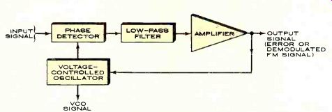
In the phase-locked-loop circuit, the "input" reference frequency is phase-compared with the output of whatever is to be controlled. In an FM tuner, the VCO output tunes the critical circuits. In a turntable, a speed-sensing device substitutes for the VCO and the error-output signal controls the motor drive.
--------------
THE NEW DISTORTIONS: TIM, SID, ETC.
SPECIFICATIONS having to do with the "speed" of audio circuitry have recently caught the attention of some audiophiles, who believe that "transient intermodulation distortion" (TIM) and "slew-induced distortion" (SID) result from certain inadequacies in the response time of audio circuits.
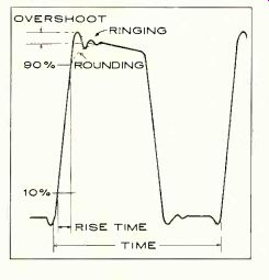
One might assume that all circuits respond instantaneously to input signals, but this is not so. Each circuit has its own rate of response, which can be judged by its "rise time." Suppose we feed an instantaneous pulse into a circuit and observe the circuit's response at its output. The time that elapses between the point at which the circuit has reached 10 per cent of its final output level and the point at which 90 per cent of output is reached is referred to as the rise time of the circuit. Rise times for amplifiers are typically on the order of microseconds, which means that it takes several microseconds for the output level to go from 10 to 90 per cent of its final value.
The slew rate of a circuit is a measure of the maximum rate of change of voltage with time that it is capable of. Consider the instantaneous pulse again. Theoretically, the rate of change of the voltage at the leading edge of the pulse is infinite, but if we put such an ideal pulse through any real amplifier (or other device) we will be able to observe a finite rate of change of voltage with time-a lag, in other words-at the leading edge of the waveform. Slew rates, expressed in volts per microsecond, vary over a wide range; values from about 10 up to 50 volts per microsecond can be found in audio preamplifiers and rates above 50 V/u sec in a few power amplifiers.
Certain types of distortion relate directly to the limitations on a circuit's rate of response. Transient intermodulation distortion is one such phenomenon; it may occur in feed back amplifiers (which is to say virtually any high-quality audio amplifier).
In negative-feedback amplifiers, the input signal is passed through the gain stage and part of it is then routed back to the input of the device (by the "feedback loop") and added, out of phase, to the input signal. The resulting signal passes through the amplifier "corrected" for any nonlinearities the gain stage introduces.
This works well with steady-state sine-wave inputs, but what about such rapidly varying inputs as musical waveforms? When the input signals change very rapidly, problems can arise if the returning feedback signal undergoes any delay; the result is TIM. Distortion can also result from the inability of an amplifier to slew fast enough. Imagine an amplifier called upon to handle signals at the high end of its rated power band width. As the amplitude at which it is called upon to produce these signals is increased, it will be driven into distortion as its slew rate is exceeded, and this is slew-rate limiting or slew-induced distortion.
The degree to which TIM and SID are audibly important factors in to day's amplifier designs is still being vigorously debated.
---------------
Two things determine how well such a feedback system will work. The first is obviously the accuracy of the reference, and the second is the speed and precision with which the correction process can function. If, for example, the platter's mass is too large and the motor's power too low, the correction will be slow no matter how fast the circuitry does its job, and the turntable speed will wander accordingly.
A circuit called the phase-locked loop (PLL), developed in the early 1930's, is a refined all-electronic form of this servo scheme. Distressingly unwieldy when it had to function with tubes, it was still cumbersome with transistors until about 1970, when the first integrated-circuit PLL was introduced. Now it's popping up all over the place-stereo and quad decoders, FM tuners, even telephones.
Because the PLL works with the relative phases of the reference and the sensor signals (that is, their time relationship over much less than a full cycle of the signals), it can serve as a particularly rapid and sensitive controller for a servo system.
But what about the reference? The more accurate and stable it is, the more perfect will be the turntable's rotation.
A quartz crystal, properly ground, polished, and mounted, has a natural resonance (when it is electrically excited) that is very sharp and precise. but speed accuracy (how close it is to 33.333 rpm or 45 rpm) is really less important than freedom from the short-term variations called wow and flutter. If you measure carefully enough, you can discover not only that setting the tone arm down on the record slows the turntable slightly (because of the record/stylus friction), but that the exact degree of slowing is influenced by the intensity of the modulation in the record groove! One manufacturer of a quartz-crystal turntable is able to show a speed variation of well under 0.001 per cent when the tone arm plays heavily modulated grooves, as compared with ten to twenty times that amount with less sophisticated servo systems. Very impressive, but whether this sort of precision is really necessary is ultimately up to the ears (and budget) of the potential purchaser.
THE accuracy with which you tune the front end of your FM tuner deter mines to a great degree how much noise and distortion will be added by the tuner to the received FM signal.
And when a test report refers to "tuning ease," what is meant is not how smoothly the tuning knob turns, but rather how precisely and easily the chosen station can be tuned in with a minimum of fiddling to secure lowest distortion.
For decades, when the utmost in frequency precision has been required, tuned circuits have been controlled by quartz crystals. Such crystals, when carefully made and temperature-compensated, can provide frequency ac curacy to 0.0001 per cent (these are the same crystals that are finding their way into turntables). However, in a tuner designed to receive all the stations on the FM band, it is obviously not practical to provide a crystal for each tuned frequency-hence the frequency-synthesizing tuner. With a single quartz crystal and a combination of frequency multipliers and dividers, all the required FM tuning frequencies can be generated, each having the accuracy and stability of a quartz crystal.
FET's (MOS- and V-)
The FET (field-effect transistor) is by now pretty well known. It is often de scribed as a semiconductor device that combines the best features of vacuum tubes and ordinary transistors without any of their disadvantages. This is an oversimplification, but it's not wrong.
FET's proved to be especially advantageous in the input stages of FM tuners, where their lower sensitivity to over load made them less prone to cross-modulation of FM-station signals than bipolar transistors. (Cross-modulation occurs when the tuner is overloaded by strong stations which then appear haphazardly at several frequencies on the tuning dial.)
------------
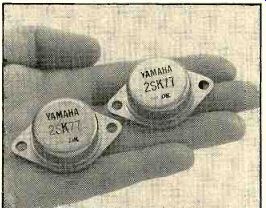
One power FET can replace as many as four or five conventional output transistors. The photo indicates their quite substantial size.
-----------------
A further evolution of the FET is the MOSFET, or metal-oxide-semiconductor field-effect transistor. These de vices have an extremely high input impedance which greatly increases the effectiveness of the tuning circuits in the front end of tuners. They also appear in dual-gate versions that have two mutually isolated control elements.
This especially versatile configuration has become common in the better FM-tuner front ends, for it allows the signal and a control bias (for automatic gain control, for example) to be applied simultaneously to the transistor without the drawbacks that would result from their interaction. MOSFET's have also become common in audio control circuits, where they are used as voltage-controlled attenuators-in effect, volume controls or switches that can be adjusted by the application of a control voltage.
Another novel type of FET is the so called "V-FET," or power FET. Conventional FET's have current limitations which make them unacceptable for use in power amplifiers; the V-FET is capable of large enough outputs for this purpose-in fact, one V-FET can replace as many as four or five conventional power transistors. Power FET's are now being manufactured by Sony, Hitachi, and Yamaha. Hitachi has even announced a power MOSFET which it will incorporate into at least one of its 1978 integrated amplifiers.
CONSIDERING the history of the audio industry, it seems likely that to day's innovative state-of-the-art component may become merely another good run-of-the-mill product tomorrow. But it is important to realize that this does not mean that the innovation originally lacked merit. On the contrary, it had so much merit that competing manufacturers rushed to build it into their own equipment, thereby reducing the unique to the ordinary.
Which should, of course, be cause for rejoicing rather than regret, for it means that everyone involved in the pleasures of hi-fi benefits. The new comer with his low-cost system sooner or later inherits the advanced innovative engineering originally supported by the interest and dollars of perfectionist audiophiles. Altogether, a very satisfactory arrangement.
As for tomorrow, a few innovations-Hall-effect tape heads, pure-metal tape coatings, digital recording (and other) techniques-are already peeping over the horizon. We have not dealt with them here because they are not yet generally available to the con sumer. Their introductions cannot be far off, however, and if they live up to their advance notices, then we can confidently say that the best is yet to come.
====================
Also see:
EQUIPMENT TEST REPORTS (Jan. 1978)
Turntables -- What Are Your Options (Jan. 1985)
Source: Stereo Review (USA magazine)