Hirsch-Houck Laboratory test results on the Marantz 2500 AM/FM stereo receiver, Sanyo RD5300 cassette deck, Sansui AU-717 integrated amplifier, Audio-Technica AT-605 audio-insulator set, and Infinity Qa speaker system.
By Hirsch-Houck Laboratories
++++++++++++++++++++++
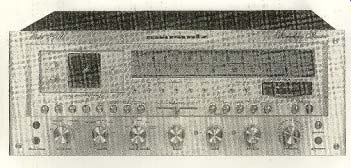
Marantz 2500 AM/FM Stereo Receiver
RECEIVERS have come a long way from Ilk their very humble beginnings twenty or so years ago as an economical combination of a basic preamplifier, a (usually) unexceptional AM/FM tuner, and a low-powered amplifier.
With today's power race between receiver manufacturers we have reached the point where the current champion, the Marantz 2500, carries a hefty 250-watt-per-channel rating. And all of the other attributes of a high-quality separate component system, including control flexibility and tuner performance, have been scaled up to match.
Although space does not permit even an abbreviated discussion of the many advanced circuit features of the 2500, its key performance ratings are a clue to its potential. For example, the audio power rating of 250 watts per channel into 8-ohm loads from 20 to 20,000 Hz, with less than 0.05 percent distortion, would make the Marantz 2500 a formidable contender among super-power amplifiers, let alone receivers. But, unlike most amplifiers and receivers, the 2500 also has a full-fledged "FTC" 4-ohm rating of 330 watts per channel from 20 to 20,000 Hz, with less than 0.08 percent distortion. The FM-tuner ratings include a 12.1-dBf 50-dB quieting sensitivity, mono and stereo distortion of 0.1 and 0.2 percent, respectively, and 50 dB of mid-range stereo separation. The 2500 is not much larger than other receivers with half its power. Its front panel, in satin-finished gold, has the familiar Marantz horizontal' tuning control. On the dial plate, with its blue-lit calibrations, are red indicators for STEREO and DLB-1 (an optional Dolby-FM decoder).
To the left of the dial area is the oscilloscope display, which has traditionally been a feature of the top-ranking tuner in the Marantz line. The 2-inch-diameter cathode ray tube serves as an AM and FM tuning indicator (showing relative signal strength vertically and FM tuning error horizontally), a multipath-distortion indicator, and an audio X-Y display of both channels simultaneously.
Next to the scope tube are its spot-positioning controls and the audio-display level control.
LED's below the dial identify the selected program source (AM, FM, PHONO 1, PHONO 2, AUX, and TAPE). Separate PEAK lights for the two channels flash when the instantaneous power approaches the maximum capability of the amplifier.
Across the full width of the panel, below the dial and scope, is a row of fifteen pushbutton switches. Four of them cross-connect two tape decks for dubbing from either one to the other and provide tape monitoring from either deck. Other buttons turn on the oscilloscope and select its display. Following a horizontal-slider BALANCE control with a center detent are buttons that control the low-frequency (15-Hz) and high-frequency (9,000-Hz) filters, both of which have 18-dB-per-octave slopes.
The remaining buttons control loudness compensation, the MPX NOISE FILTER, and FM interstation-noise muting. There are separate switches for the two sets of speaker outputs.
The knob-operated controls are in a row along the bottom edge of the panel. The input selector is conventional, except for its inclusion off a second FM position for Dolby-encoded broadcasts. This not only changes the FM de-emphasis from 75 to 25 microseconds, but also connects the DLB- I Dolby module if it has been plugged into its receptacle in the rear of the receiver. Each of the three eleven-position tone controls (BASS, MID, TREBLE) is a concentric pair with slip-clutch coupling for independent adjustment of the two channels.
The TONE MODE control knob of the Marantz 2500 has five positions, including IN and OUT settings so that the controls can be by passed. The position marked 100 Hz changes the bass turnover frequency from its normal (but unspecified) value to 100 Hz, and the 10-kHz position does the same thing for the treble control. Finally, the 100-Hz/10-kHz position shifts the turnover frequencies of both controls to their alternate values. The mid range tone control is unaffected by these actions, but it too is bypassed in the our position of the control.
Completing the front-panel features are the volume control (with forty lightly detented positions), the pushbutton power switch, a headphone jack, and two tape-dubbing jacks (IN and our) for connecting a tape deck through the front of the receiver. When this is done, the rear TAPE 2 circuits are bypassed.
On the rear apron of the Marantz 2500, in addition to the various signal connectors, there are PRE OUT and MAIN IN jacks, for inserting accessories between the preamplifier and power amplifier, and an output jack for possible use with some future discrete four-channel FM decoder. A rectangular socket accepts the optional DLB-1 Dolby Module.
When installed, it is controlled by the front-panel input selector in its FM 25-microsecond position. Insulated spring clips are used for the speaker outputs and binding posts for the antenna connections. There is a pivoted ferrite-rod AM antenna. Screwdriver adjustments control the brightness and focus of the oscilloscope and the FM muting threshold.
One of the two a.c. outlets is switched (both are of the three-prong grounding type).
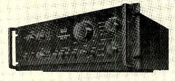
A prominent feature of the rear apron is the cooling-fan exhaust. The output transistors of the Marantz 2500 are mounted in a rectangular tunnel, with long individual cooling fins (actually rods) attached to the transistors and extending into the tunnel. The fan draws air from the top of the cabinet through the tunnel and expels it out the rear. Normally it operates at a very low speed, but if the tempera ture rises beyond a certain point the fan automatically switches to a higher speed. The Marantz 2500 is 19 1/4 inches wide, 7 inches high, and 17 1/4 inches deep. It weighs just un der 60 pounds. Price: $1,750. A walnut-veneer wooden cabinet is available as an option (about $45). The Dolby module DLB-1 is about $50.
Laboratory Measurements. The most impressive feature of the Marantz 2500, from the standpoint of our laboratory tests, was its totally cool operation. At no time during the FTC preconditioning period or the high-power tests that followed did any part of its exterior become even faintly warm to the touch.
We have never encountered any other audio component that remained as cool in operation as the Marantz 2500.
Under normal conditions, the fan operates so slowly that it cannot be heard, even close up. Only a faintly warm, barely perceptible breeze emerging from the rear of the fan grille gives a hint of its presence. After about five minutes of one-third-power operation the fan switched to high speed with a roar that could hardly be overlooked. Since this would hap pen only when the amplifier was delivering considerable power (presumably to loud speakers), it is unlikely that it would present any problems in actual practice. The thermal "inertia" of the cooling rods is apparently quite low, since a minute or two after a normal power-output level was restored the fan dropped back to its lower speed.
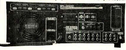
above: The efficient cooling system of the Marantz 2500 employs a variable-speed
fan. Its exhaust outlet is visible at the lower left of the rear panel.
Speaker outlets are located immediately above the fan, and the signal jacks
are visible at the lower right of the panel.
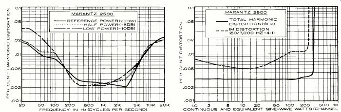
In its fully "heated" condition, the Marantz 2500 delivered 306 watts per channel to 8-ohm loads (at 1,000 Hz) at the clipping point. The 4- and 16-ohm clipping outputs were 473 (!) and 189 watts per channel, respectively. At 1,000 Hz, the harmonic distortion was less than the residual of our test equipment (about 0.003 percent) from 0.1 to 100 watts, increasing to a barely measurable 0.0035 percent at 250 watts and 0.0045 percent at 300 watts just before clipping. The intermodulation distortion (1M) was between 0.005 and 0.01 percent from 1 to 100 watts, 0.012 percent at 200 watts, and 0.05 percent at 250 watts. At the rated 250-watt output, the total harmonic distortion (THD) of the Marantz 2500 was Jess than 0.003 percent between 300 and 4,000 Hz and about 0.02 percent at 20 Hz and 20,000 Hz. It was not significantly different at lower power levels.
The Aux-input sensitivity was high, so that only 36 millivolts input was needed for a 10 watt reference output. The phono sensitivity was 0.38 millivolt. The respective unweighted signal-to-noise ratios were 79 and 69 dB. The phono input, in spite of its high gain, did not overload until a very high 220-millivolt input was applied.
The tone controls could be set to produce almost any desired frequency response.
When the 100-Hz/10-kHz switch setting was used, the control action was very subtle and concentrated near the limits of audibility. In the "normal" condition, the bass turnover frequency was adjustable from about 150 to 400 Hz and the treble-control action hinged at about 3,000 Hz. The mid-range control had its principal effect between 600 and 1,200 Hz.
The 15-Hz filter had no significant effect in the audio-frequency range. We would strongly suggest leaving it switched in at all times, since this amplifier is capable of destroying most speakers if, for example, somebody dropped a pickup onto the surface of a record. The high-frequency filter response was down 3 dB at 9,000 Hz, as rated, and its 18-dB-per-octave slope makes it one of the most effective high-cut filters we have seen in many years. The loudness-control action was moderate, and it boosted both low and high frequencies. The RIAA phono equalization was flat, within ±0.25 dB over the extended range of 20 to 20,000 Hz. When measured through the inductance of a phono cartridge, the phono response rose slightly at high frequencies to a maximum of +1.5 dB at 20,000 Hz.
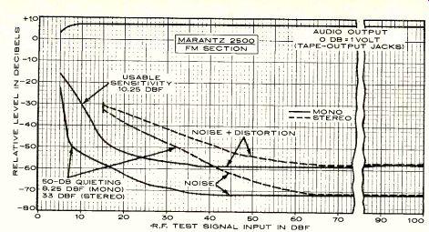
The performance of the FM tuner section provided a few surprises also. The IHF usable sensitivity of 10.25 dBf or 1.8 microvolts (uV) was good by any standards, but this is one of those rare receivers whose quieting curve is so steep that its 50-dB quieting sensitivity is less than its IHF sensitivity. In this case it was at 8.25 dBf (1.5 uV), with 5.6 percent THD.
This indicates that the tuner quiets at remark ably low signal levels, while its distortion characteristics are more "normal" for a top quality tuner. The stereo IHF usable sensitivity was 15 dBf (3 IN), set by the stereo switching threshold, and the 50-dB quieting point was reached at 33 dBf (24 uV) with 0.7 percent THD (also representing above-average stereo performance).
The ultimate quieting was 71.5 dB in mono and 70.5 dB in stereo, but these figures were limited by the tuner's residual (and inaudible) hum rather than by its hiss level. The FM distortion was 0.13 percent in mono and 0.15 percent in stereo. In stereo, with out-of-phase (L- R) modulation, it was 0.36 percent at 100 Hz, 0.1 percent at 1,000 Hz, and 0.56 percent at 6,000 Hz.
The stereo-FM frequency response was within ±0.2 dB over the full 30- to 15,000-Hz measurement range (and it was down only 0.3 dB from its mid-range level at 15,000 Hz). The channel separation was between 50 and 57.5 dB at frequencies from 350 to 8,500 Hz; it was 40 dB at 30 Hz and 37 dB at 15,000 Hz.
The FM capture ratio was 1.05 dB at a 65 dBf (1,000-pN) input and 1.56 dB at 45 dBf (100 pN). The respective AM rejection figures at these inputs were 63 and 72 dB. The image rejection was 88.5 dB and alternate-channel selectivity was 76 dB. Adjacent-channel selectivity was 9 dB. The factory setting of the muting threshold was 17 dBf (3.8 pN), which we found perfectly satisfactory, although it could have been adjusted easily if this had been desired. The stereo switching threshold was 15 dBf (3 pN). The 19-kHz pilot carrier leakage was -70 dB, and the tuner's hum level was-71 dB. The only measurement made on the AM tuner section was of its frequency response, which was down 4.5 dB at 20 Hz and 6 dB at 4,000 Hz relative to 1,000-Hz.
Comment. If we had to give a capsule re view of the Marantz 2500, we would say that (for a receiver, at least) it has an average-quality AM tuner, a considerably better-than-average FM tuner, and a superb audio amplifier. The amplifier should not be compared only to those in other receivers. It ranks with the most powerful amplifiers one can buy for home use, and it is a very, very good one in addition to being the coolest, by far, that we have tested. For those who are concerned with slew-rate considerations, we measured a 30-volt-per-microsecond slew rate on the Marantz 2500, which is certainly more than adequate. Also, with a mixed 19,000- and 20,000-Hz input signal driving the amplifier to within 0.1 dB of its clipping condition, the only distortion product detectable in the audio range was a -76-dB component at the 1,000-Hz difference frequency.
Obviously, in matters of performance, the Marantz 2500 is a truly first-rate product.
What about the human-engineering aspects of this massive "all-in-one" unit? In most respects we would have to rate it good to excel lent. An oscilloscope, though expensive, is the ideal tuning and multipath-distortion indicator. All the controls worked smoothly, with no surprises (and with all that power available, there had better not be any sudden noises!). The Dolby-FM sound was truly excellent, and this is one of the few receivers with Dolby processing that makes Dolby broadcasts sound unequivocally better than they do in their unprocessed state with a 75-microsecond tuner de-emphasis.
We found that the Model 2500 was far easier to handle and install than its 60 pounds would suggest. A centrally located toroidal-transformer power supply, which minimizes mass unbalance, is largely responsible for this happy fact. In addition, we are pleased to note that the receiver is somewhat lighter than many of its less powerful competitors.
Our one complaint about the Marantz 2500 is that, when listening to FM even with our least efficient speakers, we were never able to operate the volume control above the lowest quarter of its range. With more normally efficient speakers we rarely moved the knob beyond the lowest four or five steps (out of a total of forty). This is a function of the tuner section's output level, and a tuner-level adjustment accessible from the rear or bottom of the receiver would have been helpful.
Aside from this minor criticism, we found ourselves completely satisfied or-better yet-totally impressed with the performance of the Marantz 2500. If you are among that large group of consumers who want high power in a receiver format, you should be aware that the Marantz 2500 is, at the moment, the most powerful of its type available.
As for the possible risk of putting all one's hi-fi eggs in a single $1,750 basket, we can only point out that the Marantz 2500 is a wonderfully robust, cool-running "basket" that evidences an intelligent, conservative, state of-the-art design approach throughout.
++++++++++++++++++++++++++++++
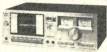
THE Sanyo RD5300 is an inexpensive, compact, front-loading cassette deck with a combination of performance and features that is rarely found in its price range. A first impression of careful design and workmanship comes when the EJECT key (one of a row of conventional "piano key" transport controls below the cassette compartment) is pressed, causing the hinged door to swing open slowly and silently. The cassette loads into guides in side the door, which is then pushed flush with the panel for operation. Almost the entire cassette can be seen through the transparent window in the door, and an orange backing allows the user to see how much tape remains on each hub. The door front is designed to come off easily, providing access to the heads for cleaning and demagnetizing.
The door is flanked by a pushbutton power switch, the index counter, and a lever marked TIMER STAND BY. This is used when one wishes to leave the machine in a ready-to operate condition (in either recording or play back modes) to be started later by an external timer switch. When the controls have been set as desired, the PAUSE lever is pressed, then the TIMER STAND BY lever. This disengages the pressure roller; when power is again applied, the PAUSE function is released and the machine goes into operation.
At the upper right of the panel are two large illuminated meters. Below them is what appears to be a large knob. On closer examination, it proves to be a pair of concentric controls surrounded by an adjustable ring whose reference mark can be set against a calibrated scale on the panel. These controls serve a dual purpose, setting both the recording and playback levels (this is one of the few concessions to economy that we found in the RD5300). Since these settings are almost certain to be different for the two modes of operation, the reference ring can be set to match the knob index mark when recording. Then, regardless of where the controls are set for playback, it is easy to return them to the pre set recording level.
The remaining controls are a row of push buttons along the lower right portion of the panel. The RD5300 has separate recording-bias and equalization controls. The latter consist of two mechanically interlocked but tons marked NORMAL and CrO2/FeCr (for 120- and 70-microsecond characteristics), and the former is a two-position button marked HIGH and Low. Two red LED's above the EQ buttons show when correct recording conditions have been established for CrO2 and FeCr tape (the latter uses LOW bias and 70 microsecond equalization).
Other buttons activate the recorder limiter (which goes into operation at levels above 0 dB to prevent distortion) and the Dolby system (a red LED shows when this is in use) and switch the recording inputs between LINE and mtc sources. There are two microphone jacks and a stereo-headphone jack on the front panel. The signal connectors, including a DIN socket, are on the rear of the machine. The Sanyo RD5300 is about 16 1/2 inches wide, 10 1/2 inches deep, and 6 1/4 inches high. It weighs slightly more than 13 pounds. Price: $179.95.
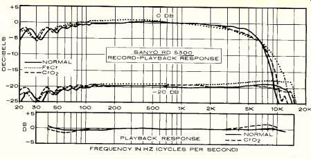
Laboratory Measurements. Although the instruction manual for the Sanyo RD5300 does not specify the tapes for which it has been adjusted, a test curve supplied with our sample indicated that it had been set up for TDK AD ( NORMAL), TDK SA ( CrO2), and Sony FeCr (FeCr). It is our practice whenever possible to use the manufacturer's recommended tapes in our tests, but on measuring the response with TDK AD it was apparent that the machine was under-biased for it, thus giving a rising high-end response. Similar but slightly less extreme results were obtained with Scotch Master and Maxell UD-XL I. We obtained the flattest frequency response with Memorex MRX2, which was used for our other tests.
The overall record-playback frequency response at a-20-dB level, with MRX2 tape, was within ±1 dB from 70 to 13,000 Hz. The rolloff of response at lower frequencies was gradual, but it dropped sharply above 13,000 Hz. With the CrO2 settings the TDK SA gave a very flat response, within ±1 dB from 40 to 14,000 Hz. Maxell UD-XL H was also tried; it had a marginally better high-end response, extending to 15,000 Hz. A true CrO2 tape, BASF Chromdioxid Super, gave a slightly peaked high-end response, reaching ±3.3 dB at 14,000 Hz. Ferrichrome tape gave a response much like that of the CrO2 tapes, with in ±1.5 dB from 60 to 15,000 Hz.
The playback frequency response (normal) was measured with the new TDK AC-337 test cassette. It was within ±0.7 dB over the 40- to 12,500-Hz range of the test tape. The CrO2 (70-microsecond) playback response, measured with a Teac 116SP test tape, was within ±1.5 dB from 40 to 10,000 Hz. The tracking of the Dolby circuits (the change in overall record-playback response, with and without the Dolby system in use) was acceptable, showing deviations of up to 2 dB up to around 12,000 to 13,000 Hz at levels of-20 and-40 dB.
For a recording level of 0 dB, a line input of 55 millivolts (mV) and a microphone input of 0.2 mV were required. The microphone input overloaded at a rather low 24 mV, suggesting a need for caution when making recordings of loud live performances with high-output microphones. The limiter worked effectively (al though it would not affect microphone-amplifier overload). It had no effect until the level slightly exceeded 0 dB, yet reduced a +10-dB signal to the equivalent of 1.5 dB with negligible distortion. The meters had a 10 percent overshoot on 0.3-second tone bursts.
From a 1,000-Hz signal recorded at 0 dB, the maximum playback level was 0.82 volt with MRX2, 1.1 volts with TDK SA, and 0.86 volt with FeCr tape. The playback distortion (third harmonic) from a 0-dB signal level was 0.6 percent with MRX2, and 1.6 percent with the other tapes. The reference level of 3 percent distortion was reached with input levels of +5 dB, +2.5 dB, and +3 dB with the MRX2, SA, and FeCr tapes. The standard Dolby level of 200 nW/M falls at a +2-dB meter reading, and the indicated level was within 0.5 dB of the correct value. The signal-to-noise ratio referred to the 3 percent distortion condition for the above three tapes was, respectively, as follows: unweighted, 50 dB, 51.5 dB, 47 dB; IEC "A" weighted, 58.3 dB, 61 dB, 57.5 dB; CCIR/ARM weighted, 55 dB, 57.5 dB, 56 dB; and CCIR with Dolby, 64.7 dB, 66 dB, 61 dB. The noise level through the microphone inputs at maximum gain was 9 dB higher than through the LINE inputs, but at lower gain settings it was considerably less.
The unweighted rms flutter of the Sanyo RD5300 was 0.07 percent both in a combined record-playback measurement and with an Aiwa test tape. The interchannel crosstalk with a TDK AC-352 tape was-50 dB at 1,000 Hz. The transport rewound a C-60 cassette in about 82 seconds. The headphone listening level, with 200-ohm phones, was reasonably good. It was not affected by the setting of the playback-level controls.
Comment. To judge the value offered by the Sanyo RD5300, consider its features: a very smooth-working front-loading mechanism, timer operation, separate bias and equalization switches for the three basic tape formulations, a peak limiter, microphone in puts, headphone output, and Dolby noise reduction. This is what one might expect in a recorder twice the price of this one, and we were frankly surprised to find all these features in such an inexpensive product. Just about the only features found in some higher price decks and not in this one are a memory-rewind system, separate recording- and playback level controls, and microphone-line mixing.
The Sanyo's features would be of little significance if the machine did not also perform well. It does-and not merely "well," but rivaling in most respects all but the most deluxe and expensive cassette recorders. For example, when we recorded interstation FM tuner hiss at a -10-dB level, the playback sound was essentially indistinguishable from the input.
Because of its very flat response, low distortion, good signal-to-noise performance, and a flutter level well below what we have measured on some more costly machines, the Sanyo RD5300 left us with that pleased feeling that sometimes follows our product testing. We had found a component that not only did what was claimed for it, and more, but also did its job much better than one could reasonably expect from a unit in its price range. In fact, we have seen many recorders at twice the price that could not match this one in total performance. If we were inclined to give "best buy" ratings, this machine would certainly qualify.
-------------
FREQUENCY IN HZ (CYCLES PER SECOND)
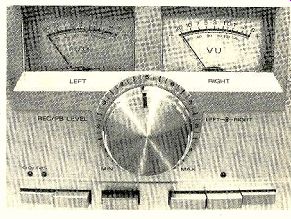
------- A large knob for setting recording and playback levels dominates the Sanyo RD5300's front panel.
+++++++++++++
Sansui AU-717 Integrated Amplifier
SANSUI'S finest integrated amplifier, the AU-717, has been designed, according to the manufacturer, to "solve the audible problems of Transient Intermodulation Distortion (TIM)." To this end, it incorporates a fully direct-coupled power-amplifier section whose frequency response varies less than +0,-3 dB from 0 ( d.c.) to 200 kHz. The amplifier's power rating is 85 watts per channel from 20 to 20,000 Hz into 8-ohm loads, with less than 0.025 percent total harmonic distortion.
The preamplifier section of the AU-717 has two capacitor-coupled stages (these are the only capacitors between the signal inputs and the speaker outputs). It has very impressive specifications for frequency response, equalization accuracy, and noise levels. Like some other recent amplifiers, the AU-717 has dual power supplies, including separate power transformers, for its two channels.
The Sansui AU-717 is finished entirely in black, with highly legible panel markings and red index lines on the knobs to show their set tings clearly. The input selector at the upper right of the panel has positions for two high level and two phono sources. The LED indicators next to the knob light up to show at a glance which input has been selected. To the left is a large volume knob that operates a thirty-two-step attenuator with light but positive detents. At high settings, the volume is varied in 1-dB steps, increasing to 2-dB steps between-12 and-40 dB and still larger steps at lower settings.
The AU-717 has exceptionally comprehensive tape-recording and monitoring facilities.
Three mechanically interlocked buttons channel either the SOURCE or the TAPE PLAY signals from one of two tape decks through the amplifier. Next to them is the COPY switch, whose SOURCE position connects the selected program to both pairs of recording outputs (as is the practice on most amplifiers). In the TUNER position, the program is connected to the tape recorders regardless of the setting of the input-selector control, so that it can be re corded while one is listening to a record, tape, or other program source. Two positions of the COPY switch interconnect the two tape decks for copying from either one to the other, during which time one can listen to any other pro gram through the amplifier (or, by pressing the appropriate TAPE PLAY button, monitor the output from either tape deck). Finally, there is an OFF setting which removes all signals from the tape-recorder output jacks.
To the left of the tape controls is a MUTING switch that drops the audio level by 20 dB for temporary interruptions. A small BALANCE control knob below the volume control has a center detent. At the lower center of the panel are four lever switches for LOUDNESS compensation, HIGH filter (6 dB per octave above 10,000 Hz), SUBSONIC filter (cutting off below 16 Hz), and TONE control defeat.
Each of the two tone controls has eleven detented positions. Next to each knob are two buttons that select its turnover frequency.
For the treble control these are 3,000 and 6,000 Hz; for the bass control they are 200 and 400 Hz. At the upper left of the panel is the SPEAKERS switch, which connects either, both, or neither of two pairs of speakers to the amplifier outputs. Below it is a PHONES jack and a lever switch for POWER. A red LED power/PROTECTOR light at the upper-left corner flashes on and off for several seconds when the amplifier is first turned on (before the amplifier outputs are connected to the speakers), after which the light glows steadily. Any d.c. offset voltage at the outputs, caused by an overload or a component failure, instantly disconnects the speakers and causes the light to blink until the power has been shut off and turned on again (with the fault remedied).
In the rear of the AU-7I7, insulated spring clips are used for speaker connections. In addition to the various signal input and output jacks, there are PRE OUT and POWER AMP IN jacks which are normally joined by a three-position slide switch below. To use the preamplifier and power amplifier separately, or to connect a signal-processing accessory between them, the switch is moved to one of its SEPARATED settings. One of these retains the fully direct-coupled operation of the power amplifier, while the other connects a blocking capacitor in the signal path for use with devices that may have a d.c. voltage at their output. One of the three a.c. outlets is switched.
The Sansui AU-717 is 17 inches wide, 15% inches deep, and 6% inches high. Handles and protective "bumpers" for the back panel are supplied; their use is optional. The amplifier weighs about 39 pounds. Price: $450.
Laboratory Measurements. The hour of preconditioning at one-third rated power, followed by five minutes at full power, resulted in only a moderately warm amplifier, even directly above the power transistors. With both channels driven at 1,000 Hz into 8-ohm loads, the outputs clipped at almost exactly 100 watts per channel. The 4- and 16-ohm clipping levels occurred at powers of 128 and 64 watts, respectively.
The total harmonic distortion (THD) at 1,000 Hz was less than 0.004 percent from 0.1 watt to about 80 watts output, increasing to 0.01 percent at 90 watts just before clipping occurred. Th.; intermodulation distortion (IM) was 0.036 percent at 0.1 watt and 0.015 percent from several watts to more than 90 watts output.
At full power, the THD was less than 0.016 percent (typically 0.01 percent) from 40 to 20,000 Hz. It appeared to increase slightly at lower frequencies, but this proved to be residual distortion in our signal generator. The actual amplifier distortion was unmeasurable.
The signal level required to drive the amplifier to a reference output of 10 watts was 49-millivolts at the high-level inputs and 0.84 millivolt at the phono inputs. The unweighted signal-to-noise ratio referred to 10 watts was 83.4 dB (high-level) and 77.1 dB (phono), both excellent figures. The phono-preamplifier section overloaded at a very high 380-millivolt in put level.
The tone controls affected only their indicated frequency ranges. For example, with a 200-Hz turnover frequency, the bass control had a sliding turnover frequency from 200 Hz downward, so that intermediate settings modified the response only at frequencies of 100 Hz or below. The treble-control curves were hinged at approximately the indicated frequencies. The loudness compensation boosted both low and high frequencies, the latter to a considerable degree, as the volume-control setting was reduced. However, by using the MUTING switch, it was often possible to operate the volume control in the upper part of its range and achieve a more pleasing loudness compensation.
The subsonic filter appeared to have a very gradual slope, its effect becoming visible on the curve at about 50 Hz. However, the HIGH filter was definitely of the 6-dB-per-octave type (its response was down 3 dB at 7,000 Hz), and it was of negligible value for noise-reduction. The RIAA phono equalization was extremely accurate, with an error of less than ±0.5 dB over the extended range of 20 to 20,000 Hz. There was no discernible change in phono response when it was measured through the inductance of a phono cartridge.
The measured-rise time of the entire amplifier from the AUX input was about 1 microsecond, well under the rated 1.8 microseconds. With a 2-microfarad capacitor across the 8-ohm load resistor, the response was slowed to about 6 microseconds. The slew rate of the AU-717 was the fastest we have measured on any amplifier, an impressive 60 volts per microsecond.
These characteristics, especially the high slew rate, are consistent with a low-TIM design. Although there are no accepted standards for measuring TIM, one which has been suggested is the standard CCIF difference-tone IM test. Two equal-amplitude high-frequency test tones (for example, 19,000 and 20,000 Hz) are fed simultaneously to the amplifier under test, which is driven to an output just below its clipping level. The IM products, particularly the difference frequency of 1,000 Hz, are measured on a spectrum analyzer. We have only recently begun using this test, so that our backlog of experience is limited. On a couple of receivers of presumably high quality the measured IM was only about 55 dB down, together with many other spurious products. In the case of the Sansui AU-717, the results of this test were un equivocally impressive. With the output less than 0.2 dB below the clipping point, the IM at 1,000 Hz was 75 dB below the level of each tone. No other distortion products were seen down to the noise "floor" of approximately -80 dB.
So far, we have not been able to detect TIM (or its absence) audibly. In any case, it is clear that the Sansui AU-717 is as free of this form of distortion as it is of all the more conventional types.
Comment. It is a trifle difficult to make meaningful subjective comments about an amplifier like the Sansui AU-717. So far as we are concerned, it does everything we could expect of a deluxe integrated amplifier. It does its job at least as well as any other amplifier we have seen, and better than most.
It also does it far better than is required by any audible considerations. It sounded to our ears exactly as any other fine amplifier sounds, neither adding to nor subtracting from the program material. Anything beyond that would have to be considered a defect, and we found no sign of any such in the AU-717. Those people who are convinced that TIM is a problem should by all means look at (and listen to) the AU-717. If any amplifier is free of TIM or any other slew-rate induced distortion, it is this one.
Flexibility it has-all that we can imagine needing. Good human engineering, in the marking and "feel" of the controls, separates this unit from some otherwise fine products we- have seen that were not quite as well de signed from the user's standpoint. We gave the amplifier's protective system a thorough workout, with overloads and short circuits aplenty, and it never let us down. And at no time did any part of the amplifier case become too hot to rest one's hand on. On the remote chance that our message has not been clearly understood: the Sansui AU-717 is a superb amplifier. We like it with no ifs, ands, or buts.
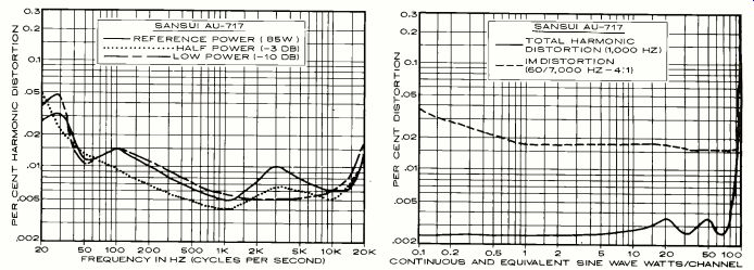
----- FREQUENCY IN HZ (CYCLES PER SECOND) CONTINUOUS AND EQUIVALENT SINE WAVE WATTS/CHANNEL
+++++++++++++++++
Audio-Technica AT-605 Audio-insulator Set
ONE of the most common problems in record-playing installations is acoustic feed back. ,This is the result of the loudspeaker output's being picked up by the phono cartridge because sound vibrations have been conducted through the installation itself (the shelving, rack, or cabinetry) or through the walls, floor, or air to the turntable base. If the vibration causes a relative motion between the tone arm and the record, the pickup cartridge responds as if it were the recorded pro gram and delivers an electrical signal at the vibration frequency to the amplifier, where it is further amplified, to take another trip through the feedback "loop"-and so on.
Depending on the frequency and strength of the feedback, the audible result may be a deep rumbling that, if left unchecked, could damage a woofer, or a higher-pitched howl that would be no less dangerous to mid-range drivers. Probably much more common is the case where the feedback is not strong enough to induce a continuous oscillation, but merely muddies the sound. In a mild case, this may go unnoticed, at least until the volume is substantially increased (for whatever reason), making the effect much more audible. However, the improvement in clarity when a case of incipient feedback has been cured is audibly unmistakable.
Related to feedback is a record player's excessive sensitivity to jarring, whether from people walking across the floor or from any thing else that happens in normal use. This is not actually feedback, since it is subsonic and cannot be reinforced by the output of a speaker, but it is much the same problem translated to a different frequency range.
There are some things that a designer can do to minimize a player's sensitivity to feed back or jarring, although the details of any particular installation are, of course, beyond his control. If the tone arm is so coupled to the platter that the two must always move as a unit, there can be no cartridge output from external vibration, and hence no feedback. This coupling is done on some record players, but it can never be completely successful because it cannot be equally effective at all feedback frequencies.
Phono-pickup response to 20- to 500-Hz mechanical vibrations applied to the turntable base without (curve A) and with (curve B) the AT-605 audio insulators supporting the base.
Another approach is to mount the record player on very compliant supports so that the entire system has a subsonic resonance frequency such as 4 Hz. Vibration coming through the supporting shelf at audio frequencies will then not be able to excite the record player system into motion, thus preventing feedback. However, this may make the system more sensitive to such subsonic jarring as might result from normal handling of the record-player controls. To minimize this problem, the mounting feet can be damped with felt or some other material that reduces the sensitivity of the system at its resonance frequency. Sometimes this is effective, but more often it is not.
Any combination of these methods can of course be used, and often is. Variations in individual installations make it virtually impossible for a record-player manufacturer to de sign a foolproof isolation system.
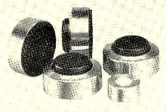
One possible solution for those plagued by feedback is to use accessory mounting feet, such as the Model AT-605 manufactured by Audio-Technica. The AT-605 consists of a set of four feet and a bubble level that can be placed on the record-player surface. Each foot, about 23/4 inches in diameter and 1 1/2 inches high, consists of an aluminum outer shell with a center section that can be run up or down on a threaded center screw over a range of approximately 1/4 inch. Although the center portion feels like it is spring-mounted, it is actually made of rubber. A felt pad on top of the foot provides some damping. The underside of the entire foot is covered by a rubber disc from which a large number of small rubber "feet" protrude.
As normally used, the four Audio-Technica feet are placed under the four corners of the turntable. A-T suggests that the original mounting feet of the record player not be used, but in any case experimentation is necessary to determine the most effective technique. For example, it may be best to use only three feet, spaced 120 degrees apart. Since each foot is rated to support up to about 9 pounds, it may be necessary with some very heavy turntables to use more than one A-T foot under each corner, or at least under any corner where the downward force exceeds 9 pounds. Still another suggested procedure is to use the -T feet under the speakers to 'e duce vibration conducted through the floor.
Since the height of each one is individually adjustable, the feet make it possible to level any turntable accurately. The bubble level supplied with the AT-605 set simplifies this job. Price: $24.50.
Laboratory Measurements. In view of the unlimited possibilities for effective installation of the AT-605 Audio Insulators, it is difficult to make any meaningful measurements of their effectiveness ("meaningful" in the sense that they would apply without exception to other installation conditions).
We set up a record player on the four vibration drivers that we use to judge the effective- ness of the base isolation of record-player systems. The four drivers were placed underneath the corners of a piece of heavy plastic on which we put the record player. With the cartridge stylus resting on a stationary record, the vibrators were driven from the swept output of our General Radio frequency –response plotter, and the amplified and RIAA-equalized cartridge output was plotted simultaneously on the chart. Then the test was repeated on the same chart with the AT-605 feet in stalled under the record player. The difference between the two curves was taken to indicate the isolation afforded by the AT-605 over the test-frequency range of 20 to 1,000 Hz. The AT-605 reduced coupling to the pick up through the turntable base by 5 to 10 dB at most frequencies from 25 Hz to just over 100 Hz. This degree of improvement might make the difference between feedback and clean re production in many cases. And, of course, it is quite possible that further experimentation, or the use of a different record player, would have yielded different results, either better or worse.
Comment. Without attempting to make more of our admittedly crude test than is war ranted, we can nevertheless conclude that the Audio-Technica AT-605 does offer a potentially worthwhile reduction of acoustic feed back from base-conducted vibration.
Whether or not the cost of the AT-605 is justified obviously depends on the severity of the problem and the degree to which it would be ameliorated by the mounting feet. Neither of these matters is predictable, but certainly the AT-605 audio-insulator feet take a step in the right direction.
+++++++++++++++++
Infinity Qa Speaker System
THE Quantum series of speaker systems from Infinity all include a novel tweeter of the company's own design. From the $1,250 Quantum Line Source to the $145 Model Qa, the same high-frequency driver is used (in multiples on the more expensive models) to give a very wide-range, well-dispersed treble response.
In the bottom-price Model Qa, a single electromagnetic induction tweeter (EMIT) is paired with a new 10-inch "Q-woofer" specially developed to complement the tweeter's characteristics. The EMIT does not resemble conventional tweeters whose cones or domes are driven by cylindrical voice coils. It has a flat, very-low-mass plastic diaphragm with a pattern of etched conductors in two parallel groups along the length of the diaphragm. The conductors are in a powerful magnetic field provided by two samarium-cobalt magnets.
The audio-signal current passing through the conductor pattern causes the diaphragm to move back and forth in the magnetic field, displacing air and creating a pressure wave that issues through four narrow slots in the metal faceplate.
Because of its limited diaphragm excursion, the EMIT can operate only at the higher treble frequencies. Therefore, the Q-woofer must handle a rather wide frequency range. In the Qa system, the crossover between the drivers takes place at 2,500 Hz. In order to have a 10-inch woofer that can function properly at 2,500 Hz, Infinity designed a unit with a phosphor-bronze voice-coil former which is claimed to have lower eddy-current effects than conventional aluminum formers and thus to provide a faster rise time.
In addition, the cone and its butyl-rubber surround are designed so that the outer portions of the cone are progressively decoupled from the voice coil at higher frequencies. As Infinity describes it, the effective woofer-cone mass therefore varies with frequency, so that good low-frequency response is combined with good mid-range transients.
The nominal impedance of the Infinity Qa is 4 ohms, and it is rated for use with amplifiers delivering from 15 to 150 watts per channel.
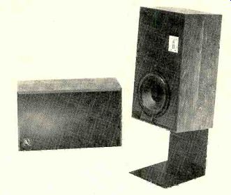
The rated frequency response is 42 Hz to 32,000 Hz ±3 dB. Although the Qa is no larger than many "bookshelf" systems, Infinity recommends that it be mounted about 12 inches off the floor and a couple of feet from a wall for best results. A metal pedestal is offered as an optional accessory for just that purpose.
The woofer operates in a sealed cabinet, covered with wood-grain vinyl, that measures 25 x 14 x 12 inches. The system weighs just under 40 pounds, and the brown cloth grille is removable. A tweeter control on the rear of the cabinet adjusts the high-frequency level over a limited range. Price: Infinity Qa, $145; pedestals, $44 per pair. Prices are slightly lower west of the Mississippi.
Laboratory Measurements. We installed the Infinity Qa speakers on the recommended pedestals for listening and measurement purposes. (The speakers can be tipped over back wards when so installed, so caution is advisable if there are small children in the home.) In the reverberant field of the room, the high-frequency response followed the shape of the microphone-calibration curve up to its limit of 15,000 Hz. When the close-miked bass-response curve was spliced to the middle- and high-frequency curve, the composite response was within ±3.5 dB from 42 to 15,000 Hz. This is impressively close to the Infinity rating, especially in view of our very different test conditions (which measure the sound in a normal listening relationship to the speakers and in a normal room instead of an anechoic chamber).
The high-frequency dispersion was superb.
There was only about 2 dB difference between the response curves measured on-axis and 30 degrees off-axis in the 10,000- to 15,000-Hz range. The tweeter level control had a range of about 3 dB, and it began to take effect at about 4,000 Hz.
The woofer distortion was measured with a 2.8-volt drive level (equivalent to 1 watt into an 8-ohm load) and also at 8.9 volts (10 watts).
Since the speaker is actually a 4-ohm unit, the effective drive levels used in testing were 2 and 20 watts. The distortion at the lower drive level was between 2 and 4 percent from 100 Hz down to 45 Hz, rising to 10 percent at 38 Hz. At higher drive levels, the measured distortion rose considerably. This result was explained when we measured the sensitivity ("efficiency") of the speaker. Driven by 2.8 volts of random noise in the octave centered at 1,000 Hz, the Qa produced a 92-dB sound-pressure level (SPL) at a distance of 1 meter from the center of the grille. This corresponds to a fairly loud listening level. The higher drive level produced a very loud 102-dB SPL. In practice one would be unlikely to operate this speaker at such levels, and the bass distortion would therefore never become excessive. Extended listening (using a 400-watt amplifier) confirmed this.
The impedance of the Qa was 4 ohms at 20 Hz, 100 Hz, and 20,000 Hz, and it reached a maximum of 15 ohms at 50 Hz and 1,300 Hz.
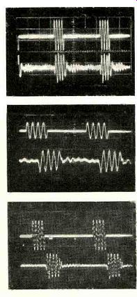
The tone-burst response was excellent at all frequencies, and we noted the rapid start-up of the woofer in the 100-Hz burst.

Comment. As usually happens, our preliminary listening experience had already given us a good idea of what test results to expect from the Infinity Qa, and we received no surprises. The Qa is an unusually clear, trans parent-sounding speaker (our apologies for using that overworked adjective, but it truly applies to the Qa). The high-end response, in particular, was at least the equal of anything else we have heard in regard to smoothness and dispersion. Furthermore, it was so well blended with the woofer output that we felt a sense of listening to a single unified sound source. Our simulated live-vs.-recorded listening test also gave the Qa perfect marks for its upper-mid-range and high-frequency ac curacy. We could hear some extra warmth in the lower mid-range or upper bass, but only upon direct comparison to the original "live" sound. Although we did not deliberately abuse the speaker, we did play it very loud, using the full potential of a 200-watt-per-channel amplifier. The speaker never sounded strained, nor was it damaged.
Reading the Infinity brochure on the Qa, we were struck by the accuracy with which it de scribed the speaker's essential sound character. The Infinity Qa has the spaciousness and smoothness claimed for it. It is undoubtedly one of the best loudspeaker values in today's market. One could pay several times as much and not get nearly so accurate a system.
The fine tone-burst response (lower trace) of the Infinity Qa at (top to bottom)100, 2,000 and 7,000 Hz typifies its response throughout its range.
Also see:
Technical Talk, Julian D. Hirsch
EQUIPMENT TEST REPORTS (Dec. 1977)
EQUIPMENT TEST REPORTS (March 1978)--Hirsch-Houck Laboratory test results on the Spectro Acoustics 210 stereo graphic equalizer. Sony PS-X7 record player, Dynavector 10A phono cartridge, Phase Linear Phase III speaker system, and Soundcraftsmen MA5002 power amplifier
Source: Stereo Review (USA magazine)