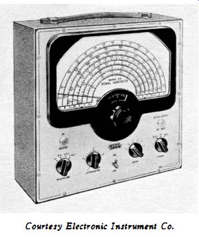
Fig. 2-1 . A comparatively simple signal generator. Courtesy Electronic Instrument Co.
| Home | Audio mag. | Stereo Review mag. | High Fidelity mag. | AE/AA mag. |
We have seen that the accuracy rating of a signal generator may refer to frequency calibration, or to microvolt output calibration. Again, an accuracy rating may be placed either on the modulating frequency or on the percentage of modulation. An accuracy rating may state the carrier distortion (total harmonic distortion in the output signal) . When the output signal is modulated, an accuracy rating may be placed on envelope distortion (harmonic distortion of the amplitude-modulated envelope ). In the great majority of signal generator applications, we are chiefly concerned with accuracy of frequency calibration. Hence, this section explains the most common methods and procedures used in frequency calibration.
A comparatively simple signal generator is illustrated in Fig. 2-1. A rating on the accuracy of frequency calibration specifies the maximum error which may occur in tuning-dial indication. This does not mean that an error is always present.
Fig. 2-1 . A comparatively simple signal generator. Courtesy Electronic Instrument
Co.
For example, if a tuning dial reads slightly high at one point and slightly low at another point, there is at least one intermediate point at which the dial reading is exactly correct.
Since we have no prior knowledge of error distribution, unless we use some method of frequency calibration we are unable to work with more exact dial settings than rated.
FREQUENCY CALIBRATION AND ACCURACY RATINGS
The accuracy rating on frequency is commonly specified in terms of the dial reading. For example, if the rated accuracy is +-1 % and the tuning dial is set to 40 mhz, the generated frequency is between 39.6 and 40.4 mhz. It is often desired to calibrate a generator to a much higher accuracy than its rating. There are two principal methods in common use for highly accurate calibration. One method, which incidentally provides maximum accuracy, is to beat the generator output against the standard frequencies transmitted by the National Bureau of Standards. Station WWV transmits on 2.5, 5, 10, 15, 20, and 25 mhz 24 hours a day. These standard-frequency transmissions can be heard on any good short-wave radio receiver.
First, tune in the WWV transmission. If the signal happens to be modulated at 440 cycles or 600 cycles or the station announcement is being made, wait until the continuous-wave (CW) transmission interval starts. Then, place the signal generator output cable near the input terminals of the radio receiver. Adjust the tuning dial of the generator for zero beat. When a zero beat is obtained the generator is operating at the WWV frequency. Of course, this is a spot-frequency check, which provides calibration only at 2.5, 5, 10, 15, 20, or 25 mhz. However, you can take advantage of the fact that most signal generators have at least a small percentage of harmonic output.
For example, even a standard signal generator may be rated for 7% carrier distortion. This rating refers to total harmonic distortion. If you tune the generator to 1.25 mhz and advance the output level , you will hear a beat between the second harmonic of the generator frequency and the 2.5-mhz WWV signal . Hence, you can easily calibrate the generator to extremely high accuracy at 1.25 mhz. Again, suppose you wish to calibrate the generator at 3 mhz. Tune in the 15-mhz WWV signal on the receiver and set the generator dial to 3 mhz. In many cases, the fifth harmonic of the generator will produce an audible beat. It is sometimes necessary to couple the generator output to the antenna-input terminal of the receiver through a small capacitor.
Harmonic calibration increases the available number of spot-frequency checks. Nevertheless, many practical situations arise which require calibration at arbitrary frequencies that are not harmonically related to WWV signals. Hence, quartz crystal oscillators are commonly used as secondary frequency standards. Note that WWV signals are primary frequency standards. In other words, WWV signals have the highest attainable accuracy, and therefore they are the standard of comparison. The National Bureau of Standards states that their atomic standards are accurate to two parts in 100 billion.
Any oscillator or generator which is zero-beat against a WWV signal is called a secondary frequency standard, which implies that there is a probable experimental error. Nevertheless, the secondary standard can be adjusted to very high accuracy. A suitable secondary standard will provide spot-check frequencies at 100-khz intervals, for example.
Hence, quartz-crystal oscillators are the second principal method used for highly accurate calibration of signal generators. Marker generators often have built-in crystal oscillators.
Some signal generators have crystal oscillators. In any case, it is easy to construct a quartz-crystal oscillator (Fig. 2-2) . Since quartz crystals are cut to operate in various circuit configurations, it is advisable to query the crystal manufacturer for his recommendation. The crystal should be tunable through the desired frequency, such as 100 khz. It is much easier to use a calibrator which has a fundamental frequency, for example, of 100 khz, instead of 99 khz or 101 khz. If a 100-khz crystal is used, its harmonics will provide spot checks at successive 100 khz intervals.
At comparatively low frequencies, such as 100 khz, lead lengths and parts layout are not critical in an oscillator circuit .
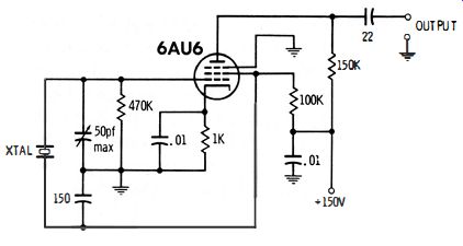
Fig. 2-2. Schematic of a shop-constructed calibrator.
Note the 50-pf trimmer capacitor connected between grid and cathode in Fig. 2-2. This is a maintenance control that is adjusted to calibrate the oscillator. Since a quartz crystal can be tuned only over a small range, it is necessary that the crystal be ground to oscillate at a frequency very slightly higher than 100 khz. Then, the trimmer capacitor is adjusted, as required, to bring the oscillating frequency to 100 khz with reference to WWV. It is not practical to calibrate the crystal oscillator directly, because it is difficult to identify the higher harmonics. Hence, it is advisable to use a signal generator to count harmonics at the outset.
Fig. 2-3 shows how 100-khz beat points are distributed on the various bands of a typical signal generator. The first band has a range from 50 to 150 khz-hence, only one beat occurs on the first band. Fig. 2-4 depicts a very simple method for...
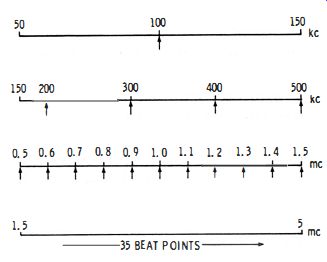
Fig. 2-3. Calibration points become more numerous on the higher bands.
...beating a crystal oscillator against a signal generator. Few shops have radio receivers with a response below 550 khz.
Hence, the arrangement in Fig. 2-4 is very useful for checking beats in the low-frequency range. A very strong beat is normally audible near the 100-khz point of the signal-generator dial. Its presence indicates that the crystal oscillator is operating as intended. If this fundamental beat is absent, check the oscillator circuit for a wiring error, or a defective quartz crystal .
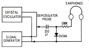
Fig. 2-4. A demodulator probe and earphones can be used to count harmonics.
After the fundamental beat has been verified, set the signal generator to the second band, depicted in Fig. 2-3 (150 to 500 khz in this example ). You will expect to hear progressively weaker beats in the vicinity of the 200, 300, 400, and 500 khz dial points. Since there are only four beat points on this band, the first four harmonics (2nd, 3rd, 4th, and 5th harmonics) are easily accounted for. It is not likely that the generator dial will indicate the exact harmonic frequencies. However, at this time we are concerned only with counting off the lower harmonics and verifying their presence.
Next, rough calibration of both of the signal generator and crystal oscillator can be made. Note that the third band in Fig. 2-3 (0.5 to 1.5 mhz ) includes the a-m broadcast band.
Hence, the output from this generator band can be fed into an ordinary radio receiver for zero-beating against various broadcast stations. Since these frequencies are specified to fairly high accuracy, the third generator band can be calibrated against available broadcast-station frequencies. This preliminary calibration is helpful, because there are more harmonic check points on the third band (11 in this example ) . It is only necessary to note the discrepancy in generator calibration at the low end, middle, and high end of the third band.
Observe whether the successive harmonic beats on the third band agree with the generator calibration as determined from beats against a-m broadcast stations. It is not likely that agreement will be exact. Hence, touch up the trimmer adjustment in the crystal oscillator as required. This rough calibration of the oscillator is very helpful in identification of harmonics on the following generator band. You are then prepared to make the final calibration of the crystal oscillator. Note that the fourth generator band (Fig. 2-3) contains 35 beat points.
Let us assume that you have calibrated the fourth band at 2.5 mhz against WWV. This one setting is accordingly known to be very accurate.
In turn, final calibration of the crystal oscillator is made as follows : With the signal generator zero-beat at 2.5 mhz against WWV, disconnect the antenna from the radio receiver, and apply the output from the crystal oscillator. It is not necessary to count harmonics on the fourth band, because the oscillator is already in rough calibration. Now, adjust the trimmer in the crystal oscillator for zero beat against the signal generator. The crystal oscillator is then calibrated to very high accuracy.
LOW·BAND CALIBRATION
Courtesy Precision Apparatus Co.
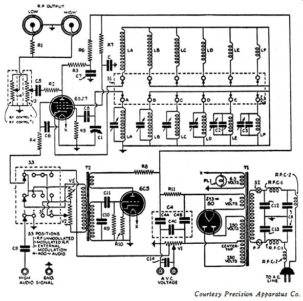
Fig. 2-5. Trimmer capacitors in the signal generator can be adjusted.
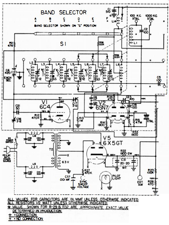
Fig. 2-6. Slug tuning II sometimes provided for tracking adj.
The crystal oscillator can be used to accurately calibrate the low bands of the signal generator. The test setup shown in Fig. 2-4 is most convenient. In most cases, a check point occurs at 50 khz (Fig. 2-3) , in addition to 100 khz. Even standard signal generators have a slight harmonic output-hence, the second harmonic of the generator produces an audible beat when the dial is set to 50 khz. In case you are calibrating a test oscillator, an audible beat can be expected when the dial is set to 150 khz-in this case, the second harmonic of the generator is beating with the third harmonic of the crystal (at 300 khz ) . Such interharmonic beats are comparatively weak, and they may pass unnoticed, unless you substitute an oscilloscope for the earphones depicted in Fig. 2-4.
There are two ways of calibrating the generator ranges.
First, the errors in dial indications can be recorded at available beat points. This may take the form of a chart or a graph. Second, when the dial error is consistently high or consistently low, it is advisable to touch up the trimmer adjustments in the generator. Fig. 2-5 shows a simple trimming configuration in which each coil is shunted by a trimmer capacitor. The trimmers are chiefly useful for exact calibration at midband on each range. In turn, it often happens that the dial indicates incorrectly at each end of its range ; this called a tracking error.
Tracking can be controlled by varying the L/ C ratio of the oscillator circuit. In other words, the inductance is increased or decreased, and midband calibration is maintained by re-adjustment of the trimmer capacitor. Because of the change in L/ C ratio, resonant frequencies are shifted at the ends of the tuning ranges. Coils in test oscillators and signal generators often have several spaced turns at the ends of the windings. When the spacing is decreased the inductance is increased, and vice versa.
Occasionally, the oscillator coils are provided with tuning slugs (Fig. 2-6) . This feature provides a convenient adjustment of the inductance. Slug adjustment has the same effect on calibration as varying the spacing between coil turns. You will often find that the tuning capacitor has slotted end plates.
These slots are bent as required during factory calibration to compromise indication error on all ranges of the generator.
It is seldom possible to improve the overall calibration by changing the factory adjustment of the slotted sections. After the dial indication has been tracked as accurately as possible, it is usually desirable to plot a graph of the residual calibration error for future reference.
HIGH·BAND CALIBRATION
High-band calibration is impractical with a 100-khz crystal oscillator, because the higher harmonics become too weak to be useful. Spot checks can be made at 5-mhz intervals up to 25 mhz against WWV transmissions. Calibration at frequencies from 25 mhz to 250 mhz must be made with suitable crystal oscillators. Some marker generators accordingly have built-in crystal oscillators which have a fundamental frequency of 5 mhz. An oscilloscope is commonly used as the beat indicator.
Maximum gain must be utilized when calibrating in the 200 mhz range, because the higher harmonics are quite weak.
A 5-mhz crystal oscillator can be calibrated directly against WWV transmissions. For example, tune in the 5-mhz WWV. signal on a short-wave radio receiver. Then, place the generator output cable near the receiver and turn the crystal oscillator on. Adjust the trimmer capacitor in the crystal circuit for zero beat. If it is more convenient to tune in a 10-mhz or 15-mhz WWV signal, the procedure is the same. In such case, the second or third harmonic of the quartz crystal is zero beat against the received signal.
Calibration of a marker generator with a 5-mhz crystal oscillator is straightforward, provided that the generator has negligible harmonic output. A zero beat will be observed at each multiple of 5 mhz on the tuning dial . The more elaborate marker generators have a practically pure sine wave (negligible harmonic output ). On the other hand, many marker generators have a strong harmonic output, and the tuning dial is harmonically calibrated on one or more bands. If your marker generator has strong harmonics, you will find numerous interharmonic beats present when checking calibration with a 5-mhz crystal oscillator.
Let us take a practical example. Consider a marker generator with coverage on fundamentals from 3.3 to 7.72 mhz, from 15 to 37.5 mhz, and from 70 to 125 mhz. The tuning dial is calibrated both in terms of fundamentals and second harmonics (Fig. 2-7) . Thus, the marker ranges are : Band A: 3.3 to 7.72 mhz on fundamentals 6.6 to 15.6 mhz on second harmonics Band B: 15 to 37.5 mhz on fundamentals 30 to 75 mhz on second harmonics Band C: 75 to 125 mhz on fundamentals 150 to 250 mhz on second harmonics
TABLE 2- 1. INTERHARMONIC BEAT FREQUENCIES. Band A Band
Of course, when the 5-mhz crystal is turned on to check dial indication, many interharmonic beats are observed between 5-mhz steps. An oscilloscope is used as the zero-beat indicator.
When maximum vertical sensitivity is utilized, visible beats are displayed at the frequencies tabulated in Table 2-1 . A brief analysis of the tabulation shows that interharmonic beats provide a great many check points in addition to the 5-mhz steps. For example, only one check point at 5 mhz would be present on Band A, if it were not for the harmonic output from the marker generator. However, generator harmonics up to the 13th contribute to interharmonic beats. Similarly, crystal harmonics up to the 13th produce visible inter-harmonic beats. Hence, there are 30 check points available on Band A. Higher harmonics produce weaker interharmonic beats. Accordingly, the 5-mhz beat point is strongest on Band A. If the scope sensitivity is turned down sufficiently, only the 5-mhz...
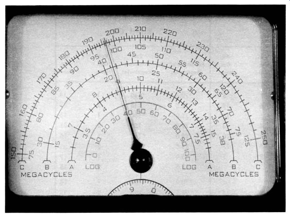
Fig. 2-7. Each band is calibrated in terms of fundamentals and second harmonics.
...beat is visible. Then, if you increase the sensitivity somewhat, you will also see beat patterns at frequencies marked by asterisks in Table 2-1. These are comparatively strong inter-harmonic beats between the lower harmonics. Finally, if you advance the scope gain to maximum, you will also see beat patterns at the remaining frequencies noted in Table 2-1.
These are comparatively weak interharmonic beats between the higher harmonics.
At first glance, the interharmonic beat frequencies seem to have no relation to the 5-mhz crystal frequency. However, each interharmonic beat frequency is related to 5 mhz by multiples.
For example, an interharmonic beat is visible at 3.5 mhz on Band A. In this case, the tenth harmonic of the marker generator is zero-beating with the seventh harmonic of the crystal oscillator. To put it another way, 10 X 3.5 = 7 X 5.
The interharmonic beat frequency is 35 mhz, which is a multiple of 5-mhz.
The accuracy of calibration at any point depends solely on the accuracy of the crystal-oscillator frequency. If you verify the crystal frequency first with respect to a WWV transmission, subsequent calibration of the marker generator will be highly accurate. Suppose that the quartz crystal is operating within +0.01% of 5 mhz, which is easily possible to realize. In such case, its actual frequency will be somewhere between 5,000,500 cycles and 4,999,500 cycles. Next, if you carefully calibrate the marker generator at 200 mhz, its actual frequency will be somewhere between 200,020,000 cycles and 199,980,000 cycles. The possible error is -+20 khz. Since conventional marker generators tend to drift noticeably on high-frequency bands, good practice dictates that calibration be checked often. On the other hand, a crystal oscillator drifts very little. Hence, the crystal oscillator need be checked against WWV only at infrequent intervals. If a tube is replaced in the crystal-oscillator circuit, a calibration check should be made after a suitable run-in period. If the crystal oscillator is run-in overnight, the tube will have stabilized, and a meaningful calibration check can be made. After careful calibration against a WWV transmission, the crystal oscillator in a marker generator is typically rated at an accuracy of -+0.01 % for a long period thereafter.
DUAL-CRYSTAL CALIBRATORS
Dual-crystal calibrators are utilized to obtain a systematic sequence of calibration points at closely spaced intervals. Fig. 2-8 depicts a typical arrangement in which either a 10-mhz oscillator or a 1-mhz oscillator can be switched into operation.
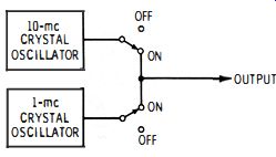
Fig. 2-8. Dual-crystal oscillator provides calibration checks at 10-mhz or
1-mhz intervals.
At first glance, it might seem that the 10-mhz oscillator is not required, since it has no harmonics that are not provided by the 1-mhz oscillator. Why should harmonics from the 1-mhz oscillator be duplicated ?
There is a very practical reason:
1. If only a 10-mhz oscillator is provided, the calibration check points are too widely separated along the tuning range.
2. If only a 1-mhz oscillator is provided, confusion may arise concerning harmonic identification-particularly on the high bands of the generator.
Let us take practical examples of these facts. Suppose we need to set a marker generator to 45.75 mhz, and can check calibration only at 40 mhz and 50 mhz. This situation occurs when only a 10-mhz oscillator is used. The generator's tuning dial is not likely to indicate exactly at either 40 mhz or 50 mhz.
Hence, it becomes difficult to estimate the 45.75-mhz setting with good accuracy. Evidently, we need to have more closely spaced calibration intervals, such as 45 mhz and 46 mhz. This requirement is easily met by using a 1-mhz oscillator.
However, suppose that we have only a 1-mhz oscillator available. In such case, appreciable generator drift can cause confusion. For example, suppose that the tuning dial does not indicate exactly at 45 mhz and at 46 mhz. Instead, the dial might indicate zero beats at 45.5 mhz and at 46.5 mhz. How can we tell which of these zero-beats indicates a 46-mhz frequency? This is not possible unless we utilize a lower-frequency oscillator to show whether the dial indication is high or low. Therefore, we switch the 10-mhz oscillator into operation first. The zero-beat at 40 mhz is clearly defined without any doubt. In other words, the marker generator will never drift as much as 5 mhz. Accordingly, it is obvious whether the 0.5-mhz discrepancy previously noted is a "high" or "low" indication on the tuning dial . Furthermore, we can count off 1-mhz intervals as follows :
1. First, switch on the 10-mhz oscillator. Zero-beat the generator at 40 mhz.
2. Second, switch on the 1-mhz oscillator (Fig. 2-8) . Then, advance the tuning dial and count off 41, 42, 43, 44, 45, and 46-mhz zero-beat points. No question remains concerning the location of 45 and 46 mhz.
3. Finally, set the tuning dial 34 of the interval between the 45-mhz and 46-mhz zero-beat points. The output frequency is then set to 45.75 mhz with quite high accuracy.
To facilitate dial settings at fractional intervals (such as 34 of the distance between 45 mhz and 46 mhz) , some marker generators have an adjustable pointer. The pointer can be turned slightly up or down on the tuning shaft by a pointer-control knob. Therefore, when you zero-beat the generator at 45 mhz, the pointer control is turned to make the dial read exactly 45 mhz. This is very helpful, because the subdivisions then read correctly, and no calculation is required to find the 34 point between 45 mhz and 46 mhz.
With reference to Fig. 2-8, it is obvious that any slight drift in frequency of either the 10-mhz oscillator or the 1-mhz oscillator will produce a beat note. Therefore, a practical dual oscillator system must either:
1. Provide a front-panel maintenance control for tuning one of the crystal oscillators over a range of several cycles. This permits the two crystal oscillators to be maintained at exact zero beat at all times.
2. Use a 10-mhz crystal oscillator and a 1-mhz LC oscillator which is locked in (synchronized with) the 10-mhz oscillator.
We find both of these methods used in various marker generators. The first method employs a very small trimmer capacitor connected across one of the quartz crystals, with a shaft which is adjustable from the front panel. This control is typically called a "Crystal Adjust" control. In practice, we merely turn the crystal-adjust control until the slow beat between the two crystals is eliminated. Or, the two crystal oscillators are zero-beat.
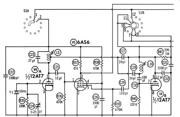
Fig. 2-9. The 1-mhz oscillator L 10 is synchronized by the 10-mhz crystal
Y1.
The second method is illustrated in Fig. 2-9. When the slug in L10 is adjusted for an oscillating frequency slightly lower than 1 mhz, the 10-mhz output from Y1 then triggers the 1-mhz oscillator. We say that the 1-mhz oscillator locks in with the 10 mhz oscillator. An LC oscillator will lock in over an appreciable range, just as a multivibrator will lock in with trigger pulses over an appreciable range. Capacitor C24 in Fig. 2-9 is a calibrating adjustment. It is used to zero-beat Y1 against a WWV signal. When Y1 is accurately calibrated, it follows that the 1-mhz oscillator is automatically calibrated to an equally high accuracy.
INTERHARMONIC BEATS
Marker generators that have dual calibrating oscillators may or may not produce interharmonic beats. This depends entirely on the generator oscillator circuit used. If the generator oscillator has negligible harmonic output, no inter-harmonic beats occur. To continue the previous example, when the 10-mhz crystal oscillator is operating, we will find beat points only at 10-mhz intervals along the tuning dial . Again, we will find beat points only at 1-mhz intervals along the tuning dial when the 1-mhz calibrating oscillator is operating. On the other hand, suppose the marker generator has appreciable harmonic output. Then, we will find additional beats (the weaker interharmonic beats) between the 10-mhz intervals on the dial , when the 10-mhz crystal oscillator is operating. And, we will find interharmonic beats when the 1-mhz calibrating oscillator is operating.
It is more convenient to use a marker generator which produces no interharmonic beats during the calibration procedure. However, generators designed for negligible harmonic output are comparatively expensive. Buffer stages must be added to maintain light loading for a good sine wave. More tubes, components, and a larger regulated power supply become necessary. In turn, the cost of manufacture is increased substantially. Most marker generators represent a design compromise in this regard ; interharmonic beats are minimized, but are not completely suppressed. The interharmonic beats are sufficiently weak that no confusion results, even when inexperienced operators follow the calibration procedure as it is outlined.
EQUALIZATION OF HARMONIC AMPLITUDES
When a simple crystal oscillator is used, such as depicted in Fig. 2-2, we find that the successive harmonics become progressively weaker. As a rough rule of thumb, technicians often consider that the strength of a harmonic is proportional to its order. For example, the tenth harmonic is roughly 1/5 as strong as the second harmonic. A crystal calibrator is easier to use if the higher harmonics are about the same strength as the lower harmonics. Hence, a harmonic amplifier is sometimes used after the crystal oscillator. The simplest arrangement is depicted in Fig. 2-10.
The plate load is an impedance which has a rising response at high frequencies. Coil L is tuned to resonate at the highest harmonic frequency to be used in calibration. Hence, the stage has maximum gain at this resonant frequency. At lower harmonic frequencies, the stage gain falls off. The Q of the load impedance is comparatively low so that the gain does not fall off too rapidly at lower frequencies. Some calibrators make use of several plate-load impedances. When the generator is switched to a higher band, the calibrator load impedance is also switched to a higher peak frequency.
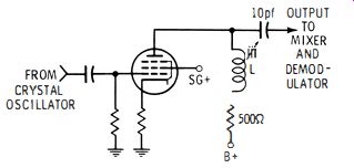
Fig. 2-10. A simple harmonic-booster amplifier.
Note in Fig. 2-10 the small coupling capacitor (10 pf) used to feed the output of the booster amplifier to the mixer and demodulator section. The small capacitor has increasing reactance at lower frequencies. In turn, this reactance variation assists the plate-load impedance in equalizing the harmonic amplitudes. Elaborate TV calibrators are designed to provide practically as strong a beat output at 200 mhz as at 20 mhz. Since more tubes and components are necessary, generators that have extensive equalization of harmonic amplitudes are comparatively costly.
MEASUREMENT OF GENERATOR OUTPUT VOLTAGE
There are several ways to measure the output voltage of a signal generator. One of the simplest methods is shown in Fig. 2-11. A field-strength meter calibrated in microvolts is used to measure the signal voltage directly. Note that the output impedance of the generator should match the input impedance of the field-strength meter. For example, if the generator has a 75-ohm output impedance, the field-strength meter should also have a 75-ohm input impedance. This input impedance takes the place of a 75-ohm resistor used to terminate the output cable of the signal generator.
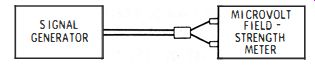
Fig. 2-11. A calibrated field-strength meter can be used to measure the signal-generator
output.
However, there are certain limitations to the method depicted in Fig. 2-11. First, a field-strength meter has a limited frequency range. For example, a vhf field-strength meter covers frequencies from 54 me to 216 mhz. A uhf field-strength meter covers the frequency range from 470 mhz to 890 mhz.
Hence, the generator output voltage can be checked only on those bands which fall within the frequency range of the field strength meter. Another limitation concerns the accuracy of the field-strength meter. Instruments with high accuracy ratings are comparatively expensive.
Another way to measure the output voltage of a signal generator is to make a comparison test, as shown in Fig. 2-12.
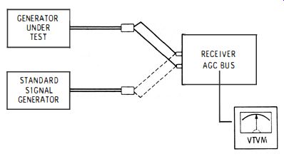
Fig. 2-12. Comparison test requires the availability of a standard signal
generator.
This requires the availability of a standard signal generator.
Outputs from the generators are compared by connecting one generator to a receiver, and then substituting the other generator. Attenuators are set to produce the same reading on a vtvm connected to the AGe line in the receiver. If the generator under test is accurate, its attenuator setting will be the same as for the standard signal generator. Errors in microvolt indication for the generator under test can be tabulated on a calibration chart, or they can be plotted as a curve on graph paper.
Recall that test oscillators do not have calibrated attenuators. A hand-drawn scale can be added to a test oscillator, and calibrated on the basis of readings obtained in the arrangement of Fig. 2-12. Sometimes it is desired to add a microvolt attenuator to a test oscillator. Several manufacturers of lab type equipment and at least one service-equipment manufacturer offer microvolt attenuators. When the attenuator is added to a test oscillator, it is also necessary to include an r-f voltmeter with a carrier-level potentiometer. The necessity for setting the carrier level to a reference value was noted in Section 1.
MEASUREMENT OF HARMONIC AMPLITUDES
High-quality signal generators have very little harmonic output. For example, a marker generator might be rated for less than 2% total harmonic distortion. A wide-range signal generator might be rated for less than 7% total harmonic distortion. On the other hand, an oversimplified generator might have 50% total harmonic distortion. The amplitude of a certain harmonic (second harmonic, third harmonic, etc. ) can be measured with either of the test setups shown in Figs. 2-11 and 2-12. First, note the level of the signal when the generator is tuned to its fundamental frequency. Then, tune the generator to twice this frequency. In turn, the level of the second harmonic can be compared with the level of the fundamental.
Let us take a specific example. Suppose we wish to measure the amplitude of the second harmonic from a signal generator tl, at has a fundamental frequency of 1 mhz. With reference to Fig. 2-12, tune the generator under test to 1 mhz and set its attenuator to a chosen level, such as 1,000 microvolts. This setting is determined by comparison with the standard signal generator. Next, with the generator under test still tuned to 1 mhz, tune the receiver to 2 mhz. The vtvm reading will be much lower. Finally, substitute the standard signal generator and tune it to 2 mhz. Reduce the setting of its microvolt attenuator to obtain the same reading on the vtvm as before.
This might be a setting, for example, of 200 microvolts. Your conclusion is that the generator under test has a second-harmonic amplitude of 20%. The same procedure can be used to measure the amplitudes of the third harmonic, fourth harmonic, etc. The higher harmonics are weaker, and they will become unmeasurable at some point. What is the total harmonic distortion ? This is defined as the square root of the sum of the squares of the individual harmonic amplitudes. For example, let us say that the second harmonic has an amplitude of 20%, the third harmonic has an amplitude of 10%, and the fourth harmonic has an amplitude of 1 %, all with reference to the fundamental amplitude. Then, the total harmonic distortion is equal to approximately 22.4% . This is the definition of total harmonic distortion. A rating on total harmonic distortion obviously does not tell the relative amplitudes of individual harmonics. Hence, we are often interested in breaking down a total-harmonic distortion figure into its individual harmonic amplitudes. In theory, a signal generator has an infinite number of harmonics in its output.
However, in practice, we find that nearly all the distortion is contributed by the second and third harmonics.
COUNTER CALIBRATION
There is a growing trend to the use of precision electronic counters for calibration of signal generators. Basically, a counter is an electronic switch that operates on each cycle of the sine-wave input. The number of times that the electronic switch opens and closes is indicated by an illuminated scale.
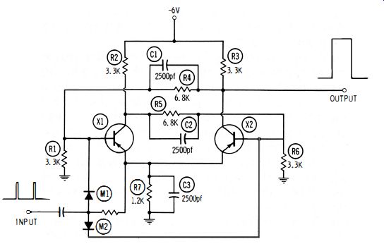
Fig. 2-13. Flip-flop circuit.
A counter also contains a precision time base. This time base permits the electronic switch to operate for a desired period, such as 0.001 second. Then, the electronic switch is turned off.
Suppose that the counter measures a 1-mhz frequency from a signal generator. If the time base is set for 0.001 second, the counter will read 1000. On the other hand, if the input frequency is more or less than 1 mhz, the counter will read more or less than 1000. Why are counters used as secondary frequency standards? It is because they are very easy to operate, can be designed for high accuracy, and save time when frequencies must be checked often. Let us see how a counter works. Its basic unit is a flip-flop circuit, such as shown in Fig. 2-13. Transistors X1 and X2 conduct and cut off alternately. Thus, there is one output pulse for two input pulses. The output pulse is fed to another flip-flop. In turn, four input pulses produce one output pulse. Diodes M1 and M2 are called steering diodes. They are alternately biased beyond cutoff by X1 and X2. In turn, the incoming pulse is "steered" to the diode which is to be "flipped." How are the input trigger pulses formed ? This is shown in Fig. 2-14. The sine-wave output from the signal generator is clipped and limited to form a semi-square wave (Fig. 2-14B) . Differentiation in an RC peaker produces pulses (Fig. 2-14C) .
(A) Waveshaping units.
(B) Input and output waveforms of the limiter.
(C) Waveshapes of the RC peaker.
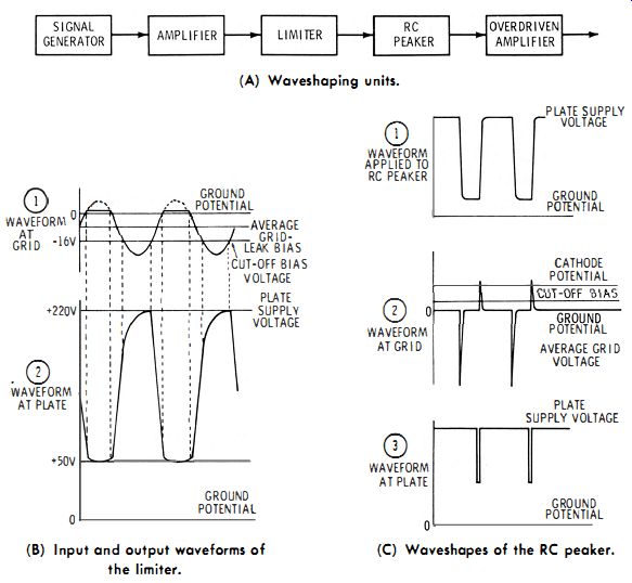
Fig. 2-14. Forming input trigger pulses.
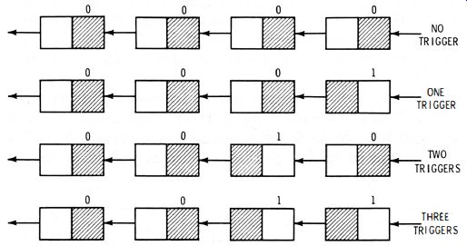
Fig. 2-15. Operation of a frequency-counter chain.
Pulses of one polarity are clipped off, and then squared by passing through an over driven amplifier. Thus, one output pulse is obtained for each sine-wave cycle from the signal generator. These output pulses are used to trigger the first flip-flop (Fig. 2-13) in a counter chain.
Operation of a simple frequency-counter chain is depicted in Fig. 2-15. Neon bulbs are commonly used as indicators to light transparencies with printed numerals. Each signal-generator cycle (pulse) causes the input flip-flop to switch. Two cycles cause the second flip-flop to switch. Readers who are familiar with digital computers will immediately recognize that the simple counter chain in Fig. 2-15 provides binary readout. In other words, or,
0= 0000 1= 1 2 = 10 3 = 11 o = OX23 + OX22 + OX21 + OX2° 1 = OX23 + OX22 + OX21 + 1X2° 2 = OX23 + OX22 + 1X21 + OX2° 3 = OX23 + OX22 + 1X21 + 1X2°
However, counters used as secondary frequency standards to calibrate signal generators are elaborated to provide decimal readout. In the decimal arrangement, additional electronic switches are used so that the binary indication is changed into decimal indication. Thus, these switches operate neon bulbs behind transparencies printed with numerals 1, 2, 3, 4, 5, etc., instead of a binary series of zeros and units. Thus, if a decimal counter reads 1,000 we know that 1,000 cycles have passed through. A decimal counter reads in terms of conventional numbers.