AMAZON multi-meters discounts AMAZON oscilloscope discounts
Give A Professional Look to Your Home Brew Equipment
Have you ever built a project and then felt disappointed with its appearance after it was done? Do you admire the beautiful projects that grace the pages of most electronics books? Would you be interested enough to spend a little time learning how to make your projects look better, be easier to build and service and perhaps work better? One of the problems facing electronics people who like to build their own gear is that there is more emphasis on circuitry than on nuts-and-bolts construction. You see this whenever you read a construction book. All too often you get a lot of "how it works" theory, a few sections of "connect the green wire to point C" construction, a "how to use it" section and schematics. That leaves a lot of open avenues for construction-great for experienced constructors, but a stumbling block for less knowledgeable people. We are going to get you started with the basics in electronic construction, and well down the road to successful project building.
A test bench can be designed using homemade equipment. Everything can be built by using ordinary tools and techniques. Granted, large and costly projects such as an oscilloscope and frequency synthesizer are beyond the abilities of most people, but some can be done at home. Why not build your next project like a pro using the following methods? Good tools are the most important part of electronic project building.
They save you time (your time is valuable!) and temper by making the work easier. Here is a minimum list of tools you should have:
• Needlenose pliers
• 1/2" blade diagonal cutters
• Adjustable wire strippers
• 25 watt soldering iron for ICs
• 100 watt soldering gun or iron for wires
• 1 lb 60/40 rosin core solder
• Screwdriver set
• Nutdriver set (especially 1/4" unit)
• Heavy duty jackknife (for deburring holes)
• 1/4" hand drill or drill press
• Set of drill bits
• 12" square/ruler
Check over your tools and be sure that all cutting edges are sharp. If you have to add tools, get good quality ones. The extra cost of good tools pays off in the long run. They stay sharper and don't break so easily. You will probably have to add tools to your present ones to handle the demands of different projects (e.g., chassis punches, etc.), but this list represents the bare minimum.
Okay, we're ready to start. We'll take each stage of the construction process step by step. To highlight the process, we are going to assemble a 5 volt, 1 amp power supply along the way. A 5 volt power supply is a great addition to any lab that works with digital ICs!
Appraise the Project. The most logical way to start an electronic project is to appraise it for the best way to build it. When you find something you would like to build, you should start by looking over the circuitry and any method of construction that may be shown. If you are a newcomer to electronics, you may want to build a kit the first time out and then start building projects out of books or from schematics. This makes electronics a lot easier if you start with a "paint by numbers" kit and gradually work up to more challenging projects.
Start by reading over the project or by checking out the schematic.
When you are reasonably familiar with it, ask yourself the following questions:
• How am I going to assemble the electronics?
• Am I going to build the completed project in a cabinet?
• Are there any critical areas in the electronics that require special care, e.g., high gain amps?
• Are there any special requirements in the mechanical construction, e. g. , shielding?
• Can I get all of the parts?
If you are building the project from a project in a book, you can answer the first four questions simply by copying the author's finished unit. The fifth question must be answered by you. If you can't get all the parts, or if they cost more than you can afford, don't build it. Instead, set the project aside, and tackle it in the future if you really have your heart set on building the item. If you are building your project from a schematic or custom building a book project, you'll have to answer these questions yourself and provide the solutions. Experience is the best teacher here. The schematic should give you some dues. Table 1-1 lists some pitfalls to watch out for as well as the corresponding solutions.
Needless to say, the list could go on, but Table 1-1 is a sample. Make allowances for these things. Leave room for metal shielding, bypass capacitors and heat sinks. Lay out parts carefully to keep input and output separate on high gain amplifiers (that includes i-f amplifiers) and leave space for heat sinks if necessary: Watch lead dress in logic circuits and VHF-UHF circuits, too. Good grounds are also very important. Keep these things in mind, along with anything else you can dig up on the project. All of the items mentioned here should influence how you build your project.
---------------------------
Table 1-1 Project Pitfalls and Solutions.
Pitfall | Solution
High gain amplifier or tuned amplifiers
Extra shielding may be required
High gain amplifier
Or tuned amplifiers
Inputs and outputs well separated.
High gain amplifier or tuned amplifiers
Power supplies remoted or shielded.
AF or RF oscillators
Good shielding and bypassing of power leads AF or RF oscillators
Sturdy mounting of coils and capacitors.
Digital logic Ics
All power supply leads must be kept short and well bypassed with capacitors.
VHF UHF circuits
All leads must be kept short.
Power supplies or power handling circuits
Good heat sinks for all power devices.
Power supplies or power handling circuits
Heavy wire where necessary to minimize losses in power.
-----------------------------------------
Collect the Parts. Now that you are reasonably familiar with what you are going to build, you can get the parts. There are many sources of electronic parts, of course, but you should start with your junk box. Don't have one? Start collecting old radios, TVs and other cast-off electronic devices and strip them for parts. You'll need hardware such as nuts and bolts, so save all that you can get. Junk boxes are good for the basic stuff you need for a project. If yours is well equipped, you might be able to build an entire project, such as a power supply, but this is rare. For any ICs or other semiconductors and parts, you may have to turn to your local dealer, so get to know him well if you don't already. Another parts route open to you is the surplus mail order dealer listed in the back pages of most electronic publications. If you haven't tried these dealers, you are missing out on some great bargains. But beware of reject or retested components. They can cause more problems than you would believe! Pros use quality, name brand parts.
This one move often saves hours of troubleshooting later! All you have to do at this time is collect the electronic components. Leave the cabinet selection until later if you are "rolling your own" project, or buy the one called out if you are duplicating someone else's device.
Once you have all the parts, you can test them if you desire. Test any used parts that show signs of being hot; otherwise, this step is optional.
Many people check all their components to save troubleshooting later, and that pays off with parts of poor quality. But this shouldn't be necessary if you use good quality parts to begin with.
Select the Cabinet. Now that you have all the electronic components together, the time has come to select a cabinet to house your project, and perhaps a chassis as well. The secret of success in selecting the right housing for your equipment is advance planning. The idea is to get a cabinet that is large enough to house all of the parts of your project, plus allow room for easy servicing and future modification. You do not want the cabinet to be too large. This is an unnecessary expense and oversize cabinets mean excessive bulk. Here's how to select the box or chassis that is right for you with a minimum of fuss.
The first step is to visit your dealer and find out what cabinets and chassis are available to you. You might also want to write the manufacturers listed in the Appendix of this guide for catalogs. Next, lay out the parts that normally mount inside the cabinet on a table. This normally includes circuit boards, large caps and transformers. Lay out the parts like you were assembling the unit into a cabinet. Allow at least 1" clearance around the circuit board (if used) and any adjacent parts. Separate heat producing parts such as transformers, power resistors and power transistors at least 2" from any other parts. The back cover is a good place for resistors and transistors, while the transformer may be mounted toward the rear. This is just a first fitting, so you don't have to place the parts exactly. Measure the height, width and depth of the layout and you have the minimum case dimensions. Consider what components you have to add to the front and rear panels. If they would interfere with the parts layout you made, add more space to the minimum dimensions. Meters and speakers are great space hogs in this respect! Continue to add parts to the front and rear panels, making corrections to your minimum dimensions as necessary. Be conservative in your estimates. A little extra room in the layout makes construction and servicing much easier. You may also suddenly discover the space for shielding, as in the case of a radio receiver project. Consider using chassis in your more complex projects. You can mount your PC boards on top, over a suitable sized cutout, and this will make construction and servicing a snap.
Chassis are also used as shielding boxes. This may be necessary in a project where many sensitive circuits must be placed in the same case. This frequency synthesizer is a project in point. It uses six fully enclosed chassis boxes to isolate the many VHF frequencies the circuits generate from each other.
Finish up your case or chassis selection by taking your dimensions and selecting a box to fit. Since you will probably have some oddball dimensions, you may have to look for a larger box or an odd sized one. With practice, selecting a case can be done quickly, with just a few measurements and the catalogs.
Build the Electronics. This is the largest step you'll probably have to make, but we are going to simplify things a bit by taking a look at the highlights of electronic construction.
To start with, there are three basic ways to assemble an electronic circuit. You can use a PC board, a perfboard or mount all the components on the project's cabinet. Often two of these techniques are combined, as it is common to mount small components such as caps, resistors or transistors on a PC/perfboard and then mount large components such as transformers and speakers on the cabinet. Which construction method is best for you? The choice is fairly easy-if a PC board is available, or if you feel you can make one, use it. PC boards are also recommended for complex digital circuits (about 10 chips or more) and critical circuitry such as high gain amplifiers. Perfboard construction is a handy method of construction for simpler, less critical circuits. Construction may be a little harder than a PC board because you have to figure out the placement of each part as you wire it up. On a PC board, the designer has determined layout for you and assembling a PC board (nicknamed stuffing) is often like building a kit. It's easy!
Another method of construction is assembling all the parts on the project's cabinet and wiring them up. This method works fine when there are few parts and most of them are made for chassis mounting. Small parts are often mounted on terminal strips to keep them from touching the chassis. You will often see this method used in power supplies such as this one and other simple projects.
Laying out your circuitry isn't necessarily difficult if you don't try to rush construction. Just take your time and use some intelligent planning and the results should be good. If you are using a commercial PC board, you can skip this part; just stick the parts in as per the pictorials and solder them! But if you are working with perfboard, or laying out a PC board, follow these hints to ease your job.
The schematic, and any other circuit information available, has the most powerful influence on how a circuit should be built. For example, if pictures or drawings are available, you might get by building your circuit from these. Or, at the very least, these illustrations can give you ideas on how to lay out the circuit to suit your own needs. So it goes without saying that you should read over any texts and illustrations available on your project before starting! There just might be enough information available to skip this section! Also you want to look for problem areas -parts of a circuit that are sensitive to component layout. Examples of these problem areas include the following:
• grounds in HX to VHF circuitry
• power supply bypassing around digital or linear ICs
• component lead lengths
A good author will point these things out and probably more, so when a suggestion is made to handle these problems, take heed! Caution: If you see many problem areas in a project and you aren't sure you can handle them all, get a PC board if available, or drop the project. This can save you grief! Suppose you are building a project from just a schematic. Now you have a challenge! There are basic ways to go about building the circuitry. First, select a board large enough to hold all of the parts, then refer to the schematic. You can often lay out the parts on the board just like the schematic- you might consider this. This makes complicated circuits easier to trace, but a well-drawn schematic is required. Otherwise, try sticking the major parts (e.g., transistors, ICs, etc.) on the board. Then stick in the smaller components around the pins of the IC or transistors they would connect to. Try to position the parts for shortest lead length. And remember how you appraised the circuit to begin with? Try to account for any pitfalls you found at that time. You may do this technique for just one stage at a time, as in complicated circuits, or do an entire circuit at once! The following are some tips to use in your layout and construction. Leave plenty of room for all parts, avoid layered construction, or the placement of resistors on top of capacitors and always use sockets on ICs. When you have a layout that satisfies you, wire up the parts. Use # 18 to #24 bare tinned copper wire for all grounds and power supply leads if possible. When you are done, check your work and plug in any ICs. You might be able to check out the board to see if it works, too.
Tackling the Cabinet. Now you get to lay out, machine and label the cabinet. And in the bargain you'll get some exercise! Start by laying out the cabinet. You should have a general idea of what goes where in the cabinet from the section on its selection. Now improve on that by collecting the parts that would mount on the front panel. Oh yes, don't forget the box you selected! Play chess with the parts by placing them on the outside of the box and moving them around until you get an arrangement that looks aesthetically pleasing. Lay out controls in a symmetrical manner-in a straight line (if you have many controls, stagger them). Balance them so they are neatly centered between the ends of the box. If possible, group the controls by function. Mark all hole locations. Masking tape works well here. Then follow the same procedure for the bottom and back of the box. Be sure that there is still room for all of the parts. If you need ideas for your cabinet layout, why not check out some commercial gear? This can be very helpful if you are stuck.
Once you have the locations marked, you can start drilling them. A center punch is recommended to punch all hole locations for greater accuracy, but this is an option. When you have all cabinet holes drilled, use the knife to deburr them. Then tackle special holes, such as square ones for displays or round ones for meters. You can cut these either by drilling holes around the inside edge of the cutout, punching out the slug and filing to size or by using a chassis punch. A sabre saw could also be used, but it would mark up a painted panel. The choice is up to you. After you are done, deburr any leftover holes and wash the box. Use detergent and water if the box is painted, or a scouring pad and detergent if it is bare aluminum. Finish up by drying the box thoroughly.
You might want to paint the box. For best results, warm up the box to about 30° to 40° C. Then use your favorite color of aerosol spray to do the job. Follow the instructions on the can and you should get good results.
Incidentally, it is often cheaper for you to buy an unpainted box and paint it yourself. Let the box dry in a warm dust-free place overnight. Then, take it and apply a light coat of clear acrylic spray. This will make application of the labels easier. Let it dry for several hours.
Now you can apply decal labels to the cabinet. If you don't have any, you should be able to get them from the larger electronics distributors or perhaps by mail order. You can also get alphabet sets from most drafting suppliers for low cost. Typical names for decals are Letraset° or Teclmilabels°. They come in sets for experimenter, ham, etc. Common words are already spelled out for you and they are very easy to use.
The drafting alphabet sets have names such as Paratipe° and Zapatone° and have only letters-you must make up the words yourself.
Applying these labels to the cabinet is easy-they just rub on with a blunt pencil. If you get a word or letter in the wrong place, it easily comes off by placing a piece of cello tape over it, rubbing it and pulling it off. Be sure that you allow plenty of clearance for the knobs when you apply the labels. After you label the front you may wish to label the rear, too. This will complete the professional appearance of your equipment! Spray the outside of the cabinet with clear acrylic spray when it is labeled to your satisfaction and let the box dry.
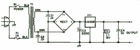
Fig. 1-1. A simple 5 volt, 1 amp power supply. C1, C2-0.01 uF disc capacitor;
C3-2200 uF 25 volt electrolytic capacitor; C4-0.1 uF capacitor; F1- lamp 3AG
fuse and holder; il - 12 volt, 50 mA lamp and holder (Radio Shack 272-322
OK); 1C1-LM 309K voltage regulator; RECT-6 amp, 50 piv bridge rectifier; S1'
SPST toggle switch; T1-12.6 volt, 1 amp filament transformer; Misc-cabinet
(LMB442 used in example), 3 wire cord and plug, binding posts, wire, etc.
Final Assembly. You are probably getting pretty excited by now be cause you are in the homestretch! Now you get to connect up a lot of loose parts and see if the project really works.
Complete the final assembly by mounting all the parts on the front panel. Install the knobs when you finish. If you did everything well so far, the project should go together like a kit-fast and easy! This is something to shoot for. Continue with the rear panel, too. Then mount the circuit board in the bottom of the box (if a board was used) with 1/2" or longer metal spacers.
Use at least four. Mount any other parts as necessary and the mechanical construction is done.
Complete the wiring and you are home free. Refer to the schematic for details (Fig. 1-1). It may be necessary to loosen or disassemble parts to wire them, so you might want to keep this in mind. Despite the best plans of mice and men, this problem crops up from time to time, so keep a screwdriver handy! Note the power supply.
Checkout. The moment of truth has come! You plug it in and there is a very good chance your project will show signs of life. If so, congratulations on a good job! If not, you'll find a carefully built project much easier to troubleshoot than a haywire rig with a maze of carelessly laid out wires and components. You really gain with a properly built project; it is more likely to work, it is easier to service and it looks a heck of a lot better to boot! Handy Dandy Soldering Iron Cooler Offer If you enjoy finding solutions to the nagging little everyday problems found in your favorite hobby, then you'll love this gadget. It is a solution to a little problem that has bugged hobbyists for years. Surely many of you have been faced with this same irksome situation: what to do with the mini-iron that you need for working on transistors and ICs when it is up to working temperature and you need the hand to do something else.
In other words, where can you put it down? You've probably tried ashtrays, saucers, boards with nails, etc. Well, finally something has been done about it-and it's not a factory-made stand. It's perfect for two reasons. First, it's cheap! (Besides, it's more fun figuring it out for yourself.) Second, the factory-built stands only give you a place to put the pesky iron down. If you are going to build a holder, you might just as well build one that controls the temperature of the iron as well. Never buy what you can build and never build a gadget to do one job if it can be made to do more.
This is a project built 100 percent from genuine junk box parts, and not the kind you have to buy. The base is an old 3" x 5" x 2" steel black crackle finished (at least it used to be) box that had been used for at least five or six other projects before finally finding respectability as the centerpiece of the workbench. Large green and red jeweled pilot lights of the 7 1/2 115v type are used in the top to show that the device is on (green), and that the soldering iron is on high heat (red) when it is withdrawn from the cradle. The lights aren't really necessary, but if you have a lot of them, they fill up two holes in the top of the box that need filling.
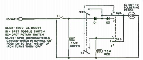
Fig. 1-2. D1, D2-300 V 3A diodes; S1-SPST toggle switch; S2-SPDT rotary switch;
S3, S4-microswitches gang-wired in normal ON position so that weight of iron
turns them off. D1, D2-300V 3A DIODES S1 - SPST TOGGLE SWITCH S2- DPDT ROTARY
SWITCH S3,54- SPOT MICROSWITCHES GANGED- WIRED IN NORMAL ON POSITION SO THAT
WEIGHT OF IRON TURNS THEM OFF.
The cradle for the iron is made from scrap aluminum, and the heat shield is a piece of scrap perforated aluminum sheet rolled into a tube and fastened to the cradle. This assembly is fastened to a piece of 1/4" square steel rod. Two holes are drilled through the cradle and the square rod and hit with two pop rivets. The rod is then drilled at a point just aft of its balance center so that when the iron is removed it will tilt forward of its own weight.
A little three-sided post out of scrap aluminum can be made and pop riveted to the top of the box. This provides the pivot point for the cradle and also a place to fasten the microswitches. The microswitches are turned off by the weight of the iron on the cradle. As you will note in Fig. 1-2, this opens the circuit across a diode, thereby cutting down the heat on the iron when it is at rest and shorting it out when the iron is removed. Removing the iron also lights the red signal light showing that higher heat is being applied. It also informs you when you don't put the iron back in the cradle properly.
Of the two switches on the front, the toggle switch controls line voltage, while the double pole triple throw rotary switch selects one of three modes. Number one position is direct line voltage or high heat. In this position the iron is connected at all times directly to the 115v AC line. In number two position the iron is in series with a 300v 3a diode while in the cradle, and directly to the line voltage when it is lifted to be used. The third and last position puts the iron in series with a diode at all times, cutting the heat still further. The third position is best for soldering tiny leads close to the bases of delicate solid state devices such as HF transistors. The number two position keeps the iron reasonably hot, but not at a high temperature.
Within five or six seconds after lifting it from the cradle it is up to full working heat.
The number one position could have been eliminated, but the switch position was there so it was wired in. It is rarely used because it causes tips to oxidize very quickly. The wiring diagram is, hopefully, self-explanatory.
This simple tool will probably be the most used addition to your bench.
Cordless Iron Tips No, not the kind of tips that heat up, the kind of tips that keep the latter heated up! In a recent advertisement, the Wahl soldering iron people set forth the claim that many users have said that their $20 cordless soldering iron is worth its weight in gold. For numerous tasks around the hobbyist's workshop it is almost indispensable, especially once you get used to having one of them. For example, they are great for antenna jobs 150' from the nearest AC outlet, small quickie soldering jobs when you don't have time for the landlocked iron to get perking and for mobile or vacation jobs to fix that intermittent when it happens. The extra fine tip that's available for these irons is great for making accurate joints on those little bitty circuit board pads that seem to be in the vogue now (you know, the ones that turn to goo with an American Beauty). One model (Wahl 7500) comes with a charger stand.
All you have to do is drop it in the stand to revitalize those two little 1200 mAh nicads inside.
Did you ever wonder whether or not the two contacts on the iron were making good connection with the matching contacts in the stand? After all, the iron element draws about 5 or 6 amps when the cells are fully charged, which represents about 10 to 15 minutes of actual soldering, so it's important to keep it up to maximum in order to have it when you need it. You can jiggle the iron around in its stand just to make sure. The charging stand as it comes from the factory consists merely of a 120v Ac to 2.5v Ac transformer and the two mating contacts (Fig. 1-3). On units that have the non-rapid charge cells, the maximum safe charging rate is 1/10 of 1200 mA, or 120 mA. Notice the clever placement of the diode in the iron itself so that reverse charging from the stand is impossible. Also, if the charging terminals on the iron accidentally short to something metal, the nicads won't discharge because the diode won't conduct that way.
Back to the point. We installed an LED (light emitting diode), polarized, in series with the red charger lead inside the charger itself. We chose to limit the charging current to 90 mA (nice and safe) with 30 mA through the LED (bright enough and also safe) -hence the 12 ohm, 1/2 watt resistor paralleling the LED. Now when the iron is dropped into its stand, it's taking a charge by the fact that the LED is releasing photons.
The actual modification is quite easily accomplished in one evening. Use a diffused red LED that requires a 3/16" mounting hole deftly drilled in the front of the stand. After checking the fit and deburring the hole, apply a couple of drops of epoxy from the inside to hold the LED nicely. Clip the LED leads to a convenient length and make small loops in them to act as tie points for the resistor and charger leads. Incidentally, there is a rather wide variance in light output, current drain and chip centering in surplus LEDs, so check the device before committing yourself with epoxy. You may find that you will have to choose from several devices to get the desired results. All that's required to custom tailor this idea to your hardware is a meter that will read at least 100 mA, a few test leads with alligator clips on them and some resistors (or a pot) around the value. You can just copy the circuit as shown in Fig. 1-3 and you'll be in the ball park.
As mentioned earlier, you may wish to use your cordless iron in the car or when on vacation, which of course necessitates bringing along the charger stand, right? Wrong! Consider whipping up a charger cord that will allow you to charge your iron directly from your automobile, boat, plane, etc., 12 volt system. That tactic involves borrowing the cord from some thing that must go with you on every vacation (Unless you're going camping in the north woods)-your electric shaver. AC coiled cords for both the Schick Flexamatic and the Norelco Tripleheader shavers will mate with the Wahl 7500 iron with minimum modification. Shave about 1/32" off of the female cord receptacle end (completely around) with a sharp knife and then file it smooth to obtain a perfect fit in the iron. Don't get carried away- 1/32 isn't very much. Yes, the cord still works in the shaver. Then wire the circuit shown in Fig. 1-4 into a standard female AC cord receptacle called a STA-TITE obtained from the local hardware emporium. Note the inclusion of the ever-present LED to show you when the iron is plugged into the shaver cord properly or when the shaver cord is plugged into the DC adapter cord properly. If the LED doesn't light, reverse either end of the shaver cord (no harm done because of that diode in the iron's case). The opposite end of the DC adapter cord is terminated in a standard cigar lighter plug. Note that this end is polarity conscious. The present standard seems to be negative ground (lighter plug shell), so wiring as shown will be correct.
By the way, this DC cord is intended as a charger cord only. Attempting to solder a connection with it plugged into the vehicle's cigar lighter socket will only replace about 90 mA of the 5 or 6 amps needed to run the iron-and that won't buy much! The figures on this circuit are identical to the AC charger: 60 mA through the 150 Ohm, 1 watt resistor combination. These figures are based upon 13v DC input, which is an average lead-acid storage battery valve. You can purchase Wahl's plastic carrying tube for the iron, or you can do just as well using a decent 1- 3/8” to 1 1/2 " mailing or paper towel tube fitted with end caps. Make it long enough to house the DC charging adapter, too.
Wahl 7500 cordless draws 5 to 6 amps from the internal batteries once the element is hot. The initial current through a cold or cool tip is about 9 amps, tapering to the above after about 5 seconds. This suggests that the working time between charges is less when the iron is continually turned on and off. If you check the iron against the clock after a full charge, you should be able to get over 12-1/2 minutes of useful heat in a continuous ON condition.
Presumably, off/on operation would yield something less than this. There are all kinds of ins and outs with something as simple as this seems to be, aren't there ?
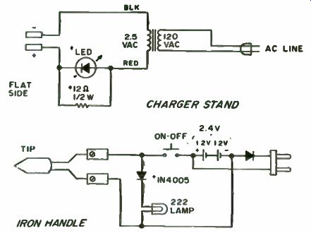
Fig. 1-3. Wahl Model 7500 iron and stand.
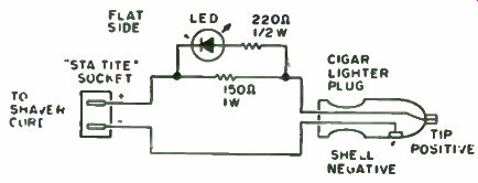
Fig. 1-4. DC charging adapter cable for Wahl Model 7500. 90 mA total: 30
mA through LED and 2200 1/2s resistor, 60 mA through 1500 w resistor.
Before you relax for the evening, here's one additional easily accomplished modification. This time it is inside the iron itself. There's a very handy little light built into the business end of the Wahl 7500, with the nasty habit of burning out too fast. The type 222 bulb is rated at 2.25v and 250 mA, but the fully-charged nicads put out 2.4v (under load) and shorten the bulb life quite a bit. If you install a silicon diode (1N4005) in series with the bulb you'll get much better bulb life, plenty of light and more battery capacity for heat instead of wasted light (remember the energy crunch!). With this addition, the bulb has 1.5v across its filament and draws 200 mA due to the drop across the diode (junction potential). The important thing here is the well-documented fact that as you lower the voltage across a lamp from its design voltage, the lamp life increases dramatically. The reverse is also true. Now that you're convinced, just remove the screw holding the bar that makes pressure contact with the shell of the lamp socket and install the diode in its stead, wrapping the anode end around the screw and soldering the blanded cathode end of the lamp socket shell (use minimum heat and remove the lamp first). While you're inside the iron case, put a small dab of GC26-01 silicone lube on the switch contact. It's a good all-around keeper-cleaner.
Note that these modifications directly apply to the model mentioned with non-rapid charge cells. However, they could be applied to other models and manufacturers and will hopefully act as food for thought for you.
Now you can relax for the rest of the evening or you could try out your newly modified cordless iron on some other interesting project or you could just admire the LED in the stand while the iron is charging.
The Solder Master
For contemporary assembly projects, use popular, screw-in element and tip soldering irons which, with tweezers and magnifying lenses, are tools of the micro-component age. Two irons can be used at the same time-a 50 watt heavy duty for large joints and a tiny tiplet for compacted PG boards.
Frustration is maintaining both irons at the proper temperature. The big element, left idle for any time, toasts its solder tinning and threatens self-destruction, requiring unplugging. The tiplet dissipates heat too fast for more than one connection and this involves impatient recovery time.
What is needed is a voltmeter for adjusting desired element tempera ture. The price of these commercial units is very high. The el cheapo answer is the commonly available light dimmer, rated at 600 watts and solid state at that. There is probably one in your junk box that will tame the heavy duty iron. But while lowering the voltage, why not also boost it briefly to help the tiplet along? A 24v, 2 amp filament transformer will solve this.
The major items can be squeezed into a 5" x 3" x 3" aluminum utility box with two outlet sockets. An available miniature meter can be pressed into service, modified with bridge rectifier and series resistor to read zero to 1.0, for reference. This works great, but has some inadequacies such as how to control the irons separately. This can be taken care of with a few more parts.
The schematic of Fig. 1-5 gives the final story, including three small toggle switches. You could also splurge on a new meter of the same size, reading 0-150v AC. The transformer primary and secondary windings can be connected in series to make an auto-transformer, if the polarity connection with 110v AC across the primary, 130v AC is measured across the combined windings. The dimmer control adjusts line voltage to the primary so that regulated output to the sockets can be varied from 0 to 130 v AC with the front panel knob. S2 and S3, miniature single pole, triple throw (center position OFF) toggle switches are installed right below the meter in line with their respective sockets. These allow either socket to be switched to regulated or line voltage, or off, independently. S1 gilds the lily in switching the meter to read regulated supply, or doubles as a line voltage monitor.
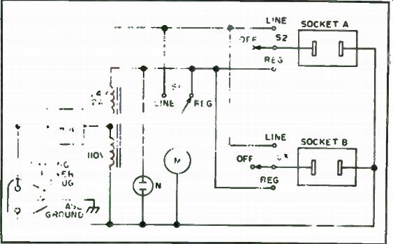
This miniature SPST switch is located immediately to the left of the meter.
Due to the pulsating waveform output from the dimmer control, voltmeter readings are not really accurate rms, but close enough for reference adjustment.
Now keep the larger iron happily idling at 70v, while using the small one switched to "line." Or switch it off temporarily, while boosting voltage to the tiplet to solder multiple joints. Start up time is reduced by briefly applying full 130 volts, but boost voltage (over 110v) should be kept to the minimum to avoid premature element failure. And when the XYL sounds chow call, both irons can be left idling at approximately 60v, for fast reheat upon return. The neon pilot light, being connected across the regulated voltage, extinguishes at about this control setting. If you set the control where the pilot is flickering, this is just right for keeping the irons warm.
Finally, use a three wire power line input to provide ground to the metal case. This is not only a desirable safety-feature, but also provides shielding for noise spikes emitted from the dimmer control. Should you use grounded tip irons, you will also want to substitute 3-prong outlet sockets rather than the 2-prong types.
You may also find some other handy applications for this voltage controller around your workshop-but don't exceed the transformer wattage rating by plugging in the coffee pot. If all parts are bought new-and dimmer controls on sale for as low as $2.98-the total cost even in this age of inflation should not exceed $15.00.
Fig. 1-5. Toggle switches are added to the dimmer.
One last warning. The push switch built into the dimmer controls serves to turn the regulated supply on and off. But, while plugged in, the unit will furnish voltage to the sockets when either S2 or S3 is switched to line.
Inadvertently leaving the irons on is avoided by leaving S2 and S3 at center position OFF when not in use.
Shutting off the main bench safety switch, which controls all outlets, is double protection.
The Third Hand
When you're soldering small components, it can be a job to hold them, the soldering iron or gun and the solder. The easy way is with a vise made with two spring-type clothespins.
Cut one leg shorter than the other, and then use small brads to the side of a small wood block. Place the item within the jaws of the two clothespins while you solder.
How to Become a Troubleshooting Wizard
In times past just about every amateur acquired, if only out of sheer necessity, some degree of troubleshooting acumen. Of course, it might be argued that rigs of those bygone days were a lot less sophisticated than rigs of today. Is that single fact really good reason for the seeming decline in general amateur troubleshooting ability? It is contended here that anyone with a knowledge of theory deep enough to pass the General class license examination can make a reasonably good attempt at troubleshooting. Of course, years of experience are needed to make a commercial troubleshooter but we are only concerned with maintaining the usual hobbyist's station equipment and not how many high technology transmitters or receivers he can fix per day or week.
Crux of the problem. Lack of familiarity and zero technique are two reasons why, to many, troubleshooting is troublesome. Consider a case in point. One person bought a near-new condition Novice CW transmitter for a song($5) because the now-General former owner found out (after the new license arrived) that it wouldn't work on 20 meters. He even knew what the main symptom showed-no grid drive to the final on 20 meters. All other bands worked fine. This person was not an experienced troubleshooter at that time. He was merely a thoughtful teen-aged amateur. He reasoned that a loss of drive on any single band in a standard simple MOPA transmitter had to be either an open coil (on that band) or some defect in the band switch. In this case the wire on the band switch that went to the 20 meter tap on the grid tank coil was not soldered properly! This little story points out one main thing that will allow successful troubleshooting. Think out the problem ahead of time with schematic in hand, to ascertain all possible causes.
Test equipment needed. After working in a lot of service shops, people have grown weary of the fellows who use the excuse that they could "fix it themselves if only they had the equipment. "While an experimenter's bench loaded with expensive laboratory grade test equipment is desirable, it is not strictly necessary for most troubleshooting. Sure if you were in the business of providing electronic service for a profit, it would be justified purchase because of the time savings on each job. The average amateur, though, only wants to get back on the air without having to wait weeks for a repair shop's turn-around time to elapse.
What constitutes "necessary" equipment? Consider, first, that the most valuable and versatile piece of test equipment is already in your possession-your head! The mind can only function, however, when given a data input concerning the problem to be solved. For this we need our learned observations about the performance of the rig vis-a-vis defect and some basic measurements, many of which can be taken with low cost or even simple home brew instruments.
Most basic in the troubleshooter's arsenal of instruments is some sort of multimeter. The traditional Volt-Ohm-Milliammeter (VOM) is often preferred over the Vacuum Tube Voltmeter (VTVM) in those cases where money or other considerations dictate that only one instrument be purchased. It is wise to purchase an instrument with a sensitivity of at least 20,000 ohms/volt (higher if possible). There are at least three reasons for this preference: portability, existence of a current range and insensitivity to rf fields. Many of the modern FET voltmeters fill the bill in the first two requirements (often better than the classic VOM) but most sadly fail in the third: They will read in error around rf fields such as exist in your transmitter.
The classic VOM will have AC and DC voltage scales, at least one current range (usually more) and at least one resistance range. Naturally, the more you can pay for a VOM the more features and ranges you can expect. You can extend the DC voltage scale of most instruments well into the kilovolt range by the use of an external high voltage probe of the type which has a built-in divider network. It is also possible to get at least a relative rf level indication through the use of a demodulator probe such as that shown in Fig. 1-6. Most manufacturers offering such probes claim operation well into VHF. The VOM is one of those "every hobbyist should have..." instruments.
Another in that category is the dip oscillator called grid, base, gate or tunnel-dipper depending upon design. These instruments have an incredibly varied range of applications around an experimenter's workshop. They can be used to find the resonant points in tuned circuits, antennas and so forth.
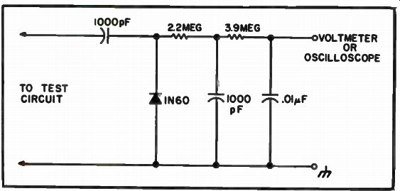
Fig. 1-6. Schematic of an rf demodulator probe for voltmeter or oscilloscope.
They can also be pressed into service as an absorption wavemeter, oscillating detector or impromptu signal generator. Best of all, they are simple to build and are low cost regardless of whether obtained in kit form or built from scratch.
In many troubleshooting procedures it might prove desirable to use a controlled, locally generated substitute signal. These are best supplied by a signal generator. Of course, a lab-grade instrument is the preferred type. It must be noted that many high grade signal generators are available on the used and surplus markets. While it might be nice to own a fine signal source, a more modest instrument will suffice for fixing the rig. It is necessary to keep in mind that troubleshooting and alignment are different procedures and that the signal generator requirements are vastly different. Commercial servicers have little trouble justifying a kilo-buck signal generator for alignment purposes. They need the superior short term stability and a high quality attenuator; you don't. A service grade signal generator will be a very useful tool in troubleshooting. These are not up to the lab grade types in performance but they can be had for less than a month's rent.
A crude form of signal generator useful for troubleshooting is shown in Fig. 1-7. This is a square wave generator operating at about 1000 Hz. Such circuits are widely used in the service industry because they can help pin point a dead stage in moments. These instruments generate the fundamen tal square wave and a boat load of harmonics that can be used out to several MHz. In most amateur work this means that we can quick check the audio, i-f and rf (on 160 to maybe 40 meters). Your crystal calibrator may also suffice as a troubleshooting signal generator. In Fig. 1-8 we have a circuit that can be home brewed from low cost TTL digital ICs. Although the possible choices of output frequency are limited in this case you can obtain almost any frequency by correct choice of oscillator crystal and division ratio. If zeroed against a frequecy standard such as WWV, this circuit can serve as an accurate method for frequency measurement. It can also be used as a regular signal generator or as a type of device shown in Fig. 1-7. In those latter applications it would be wise to provide an attenuator. If a smart troubleshooter were to be allowed only one instrument he would choose the oscilloscope. If triggered sweep and dual beam can be afforded, it would be very useful. Prices on 'scopes vary from $5/free to several kilobucks depending upon features, condition and vin tage. Many oscilloscopes, some quite nice, remain UNSOLD for lack of interest at auctions! Servicing typical ham transmitters requires several special instru ments. Most of them are the sort which ought to be in every amateur's station. One item is the 50 ohm dummy load. At a cost of only a few bucks you can have a dummy antenna which will absorb all the power you have a right to be dishing out to a real antenna. Only the utterly irresponsible would attempt to service a transmitter connected to a live antenna!
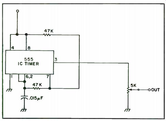
Fig. 1-7. 1000 Hertz square wave generator produces harmonics useful for
signal tracing from audio to several MHz.
Rf wattmeters and relative field strength meters Fig. 1-9 are also amongst the highly desirable. Although the wattmeter instrument is some times preferred, make no mistake about it, the old fashioned swr bridge does have a lot of good mileage left.
No one seriously expects an amateur to be as well equipped with test instruments as a commercial or factory level shop. He should, however, ...
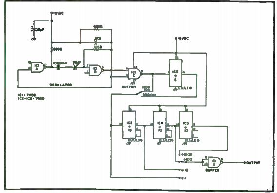
Fig. 1-8. Schematic of a TTL crystal calibrator.
... attempt to obtain those considered as basic. For some of the others he might work through th&k.)cal club to build a test gear collection of really nice pieces or arrange with certain locals to split the load by having each fellow buy certain instruments and then do a lot of lending.
Troubleshooting Procedure. Troubleshooting involves a logical, step by-step procedure for determining a fault in a piece of equipment. Best results in a minimum of time are obtained by using a method formed from a logical analysis of the problem at hand.
One thing which makes troubleshooting easier is a service manual (or at least a schematic) on the equipment. It is the wise amateur who obtains (even at a ridiculous cost) the service manuals for all of his station equipment. In most instances new equipment comes with a manual; keep it. If you buy used or for any reason are without a manual, buy one and keep it on file.
Do not expect your rig's manufacturer to be able to supply manuals indefinitely; get yours now.
One significant aid in troubleshooting is the block diagram. It is especially useful in rigs such as transceivers where a single stage might have different functions. An example of a block diagram, this one from the popular HW-101, is shown as Fig. 1-10. You can often cut the work of troubleshooting in half by doing a desk check of the service manual and block diagram before reaching for instruments to do the bench check. Note that many of the stages, shown here in dotted lines, are common to both transmit and receive functions. Although there are exceptions, you can usually overlook these stages when a defect affects only one, one function or the other.
The element of logic in troubleshooting should be almost on a priori truth (despite the philosophers who say that such cannot exist!). After all, if the set is dead (no lamps or tube filaments lit) is it wise to worry about, say, the beat frequency oscillator? Fig. 1-11 shows what is affectionately called a troubleshooting tree. Although this is not offered as a universal approach you ...
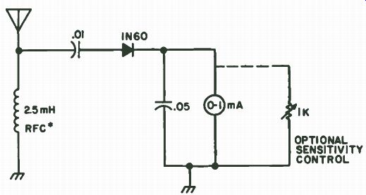
Fig. 1-9. Schematic of a simple rf field strength meter. (*Can be replaced by an LC tank circuit for greater sensitivity or use as an absorption meter.)
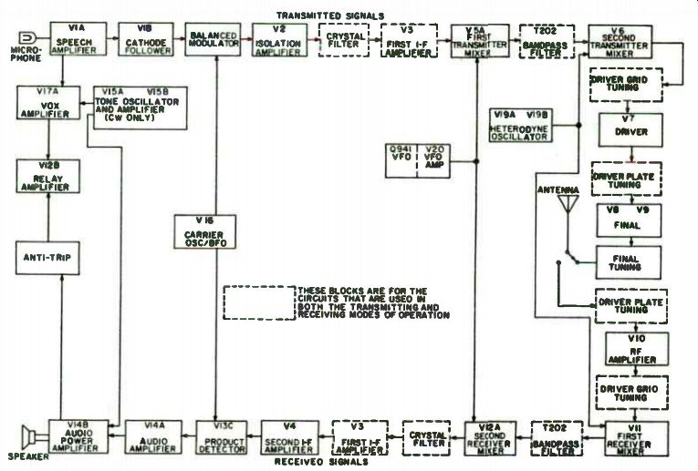
Fig. 1-10. Block diagram of a popular transceiver. ( Courtesy of Heath)
... can often at least get onto the right track by its use; it is intended only to be a point of departure guide.
Two terms pop up a dozen times in any servicing literature: signal tracing and signal injection. They are basically methods for locating a dead or otherwise defective stage. Before beginning one of these procedures, however, make certain preliminary observations. For example, can you hear noise in the speaker as you rotate the volume control? If so, the cause of the dead condition is probably prior to the volume control. What about dirty contact noise as you rotate the selectivity switch? This usually means that the fault is prior to that point. Band switch noise (again, as you change bands) could mean a fault in the rf or a dead local oscillator. What about the level of background hiss that sounds as if you were tuned to a dead band? High noise levels may tend to indicate troubles in the rf amplifier or antenna circuit. Here is one point where your calibrator is useful. Note how high the "S-meter" reads when the set is working normally. When a defect occurs, turn on the calibrator and see if it is lower. If not, suspect the antenna or feedline. These observations are of the sort that can save a lot of time. Most pros use them all day long even when unaware; it is the source of their supposed professional intuition.
Signal Tracing. The process of signal tracing involves injecting a known and controlled signal at the input to a chain of stages, then looking for it at the outputs of successive stages with a demodulator equipment signal tracer (high gain audio amplifier with a fancy name!) or oscilloscope. When you find the defective stage, you can then use the VOM or VTVM to locate the bad part. In some cases, you might want to inject an appropriate signal at the antenna terminals while in others it might be better to inject another sort of signal at the input of the i-f strip.
Signal Injection. Signal injection is a similar process. In this method you start at the output and inject an appropriate signal into the inputs of successive stages until you find one which no longer is capable of producing an output. In signal injection you begin at the output and work toward the input, while in signal tracing just the opposite situation occurs. In either event the procedure can usually be expected to ferret out the defective stage. Once found it is usually a simple matter to dig out the voltmeter and determine which component is at fault. Be sure not to overlook the obvious fault such as a bad tube or a loose connection.
When troubleshooting transmitters, you can use a demodulator probe to find relative rf levels on the 'scope or VOM. It is usually better, though, to read the DC voltage developed by the grid leak bias often used in transmitter stages. This voltage will be proportional to the rf level delivered by the preceding stage. This system works so well that it is the basis for the Motorola test set popular with FM-ers who run surplus commercial Motorola mobile equipment.
Alignment. The most exasperating mark of the neophyte troubleshooter is a wild diddle stick ( alignment tool). It is a pretty good rule to assume that alignment points never shift enough to cause a gross fault in the receiver, especially a sudden fault. The only real exception is the local ...
Fig. 1-11. Troubleshooting tree useful for finding a good jumping off point
for troubleshooting specific defects.
... oscillator. Even in that "sometimes" case there are other methods (i.e., measure the frequency) for determining its condition. One revealing way that shows whether or not the stage is actually oscillating is to measure either the grid bias or the voltage drop across the emitter resistor as the set is tuned through the range. In the case of crystal oscillators remove the rock. This will cause the bias to change suddenly for crystal pulling or smoothly in VFO type circuits. DO NOT EVER touch an internal alignment point without good reason, proper equipment and a knowledge of what it is' that you are doing. You can diddle stick a decent set to death that really only needed a small component. This is why the screwdriver technician is the bane of professional servicers everywhere.
Preventative Maintenance. There are a number of little tasks which will keep your rig in top shape for a lot of years. These generally fall under the heading of preventative maintenance ( Fig. 1-12). One task would be to check all tubes on a periodic basis, say every six months or maybe once a year.
Replace those which are defective or grossly weak. Some advocate doing a voltage check at critical points throughout the circuit especially in the power supply. It is recommended that you clean the inside of the rig, including all ...
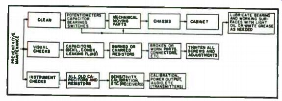
Fig. 1-12. Preventative maintenance tree.
... circuitry, with a paint brush and a mild solvent where needed. Use a switch/ control, also called tuner cleaner spray on all band switches, function switches and controls. Clean capacitor and rotary switch bearings and re-lubricate using a white grease such as Lubriplate. Peaking up alignment is NOT part of this procedure unless you can perform factory-level service.
Even in that case it should not be obligatory except every few years.
Alignment is simply not all that common a problem.
A Look at Soviet Test Gear
One of the more enjoyable benefits of being an electronic engineer is the opportunity to meet engineers from other countries. While working on international programs, many hobbyists meet engineers and trade specialists from the Soviet Union. They are anxious to improve trade relations with our country to help with their balance of payment problem. So far, the bulk of trade has been in raw materials and commodities, very dull stuff to the electronics enthusiast. Many Americans do not know much about their equipment and are very curious about its design, the type of semiconductors used, how good it is and the prices. They have a state monopoly on all manufacturing industries, so all electronic equipment is sold through state trading organizations. Test equipment (VOMs, counters, scopes, etc.) is sold by Mashpriborintorg, electronic components by Eledtronorgteknica and communications equipment by Sudioimport. This approach results in a high degree of standardization throughout their country. It also results in fewer innovative designs by their engineers.
Through a few contacts, we received two pieces of test equipment for evaluation. Both of them had useful features not found in instruments currently on our market. The first was a small multimeter, the U-4323. It is designed for the hobbyist. It is similar in appearance and outward construction to many Japanese import instruments in its price class. Range selection is done by plugging the test prods into the appropriate tip jacks. Unpacking the instrument, we discovered a small package with spare diodes and a spare meter fuse. A comprehensive operating handbook-in English-complete with circuit diagrams and maintenance data was included.
A quick glance at the panel revealed that in addition to being a conventional VOM, it contained an audio oscillator and signal generator! The output of the audio oscillator is a 1000 Hz square wave. The rf output was fixed at 465 kHz, the standard i-f for their country. It was modulated by the 1000 Hz square wave. A quick check with a communications receiver revealed that the harmonic content was quite rich. It was usable as an alignment source to well above 30 MHz. The output level of each of the outputs was a good solid 0.5 volts. The circuit is quite clever, using three germanium PNP transistors. Two are used for the 1 kHz multi-vibrator, the third is an L-C controlled oscillator which is base modulated on the package data. The packaging of the transistors was quite distinctive, being a combination of the TO-5 style and the old "top hat." All components appeared to be very well made, particularly the meter movement, which is a rugged taut band type of construction.
Diode protection is also provided. The little handbook is quite comprehensive, going into the theory of operation for the oscillator circuit. The 40 microamp meter movement is described in such detail as to permit field repair and rewinding of the meter coil. A section is devoted to the variation of readings due to changes in ambient temperature, battery voltage, meter position and the frequency of AC voltages. All measurements are illustrated by simple one function drawings. It was evident that the manufacturer realizes his instruments will be used in a wide range of climates by people who may not be too well trained.
The U-4341 is a combination instrument that incorporates a transistor tester with a high quality conventional VOM. It is a quality instrument that would be classed as a bench test instrument adequate for commercial service work. It is housed in a black plastic case designed for tabletop use.
Rated accuracy is 2.5 percent for DC and 4 percent for AC ranges. AC frequency response is from 45 Hz to 20 kHz. Both AC and DC currents are measurable. The instruction book is very comprehensive and, like the one for the U-4323, provides a lot of information for the user working in out-of-the-way places.
Another nice feature is the inclusion of special low range scales. The lowest AC current range is 300 microamps, AC is 60 microamps. The lowest DC voltage range is 300 millivolts full scale. The most interesting feature is the built-in transistor testing circuit. The meter will measure lob, leb, and lei (defined as initial collector current as measured in the common emitter configuration with zero emitter base voltage) with an accuracy of ±2.5 percent.
The quality of the instruments is quite good when the price class is considered. Both instruments are well sealed against dust and moisture.
Battery replacement is accomplished by removing the back plates. All instruments have manufacturing seals placed by their quality control department to reveal any tampering that might void the warranty. A separate certificate of inspection giving the performance specifications and quality assurance sign-off is packed with each instrument.
Reading the manufacturer's literature provided insight into the type of equipment available to the Soviet hobbyist. There appears to be no production of strictly amateur radio equipment in the Soviet Union at this time. This means that the Soviet experiment has to build his own or modify military surplus equipment. This is made available to him through DOSAFF, an organization that has no American equivalent. It is a civilian auxiliary for supporting the armed forces, and would be roughly analagous to having MARS, civil defense, the National Rifle Association, sport parachuting and other paramilitary activities rolled into one super organization. Soviet defense policy places significant emphasis on having a trained cadre of civilian radio operators available to assist the military in the event of war, so they supply individuals and clubs with equipment much in the manner that our MARS program is supposed to operate.
There are a number of test instruments in their equipment catalogs that would be of interest to hobbyists in this country. Among these is a neat little 3 inch scope. It has a calibrated triggered sweep, 10 MHz bandwidth, built-in calibration and a number of other desirable features. Again, there is a design twist-this scope is designed for the hobbyist with limited facilities to maintain his test equipment. Although of recent design, it was designed around a series of high reliability vacuum tubes to minimize the number of components.
If and when these products appear on our market will depend on the political situation. One of the major stumbling blocks is the lack of a "most favored nation" treaty with the Soviet Union. Lack of such a treaty results in drastically higher import duties out of the market. There has been a great improvement in relations between our two countries in the past few years.
Hopefully this will continue. With the ever-increasing prices of Japanese electronics, we may see a day when the USSR will be a major supplier of popular electronic equipment.
--
Link | Next: Cheap-N-Easy Handy-Dandy Testers