AMAZON multi-meters discounts --- AMAZON oscilloscope discounts
A Free Test Lab
Just about everyone needs more test equipment, or easier ways to use the test equipment he already has. Just about everyone has an old radio sitting around and this can provide the needed test equipment. You merely need to make the proper modifications to the radio, then know how to apply the resultant piece of test gear. Here are some modifications which will allow you to add a mess of handy test equipment to your shop, and still leave your old transistor radio in working order. The finished device will be everything from a speaker subber to transistor checker. It will still provide your favorite news or music while just sitting on the bench.
The first consideration is what to do about packaging the radio. You may decide to leave the radio intact and add plugs and jacks of your choice in the radio cabinet. You could run leads out from the radio cabinet and put the plugs, jacks and switches on a mini-box. Or you could package the radio complete with modifications in the box of your choice. No matter what the package you choose, be sure to decide on plugs and jacks that you already have around so you don't make all your test leads obsolete. The diagrams that follow show the use of phone jacks, but you could just as well use banana jacks or whatever. Figure 2-1 shows a typical radio schematic. Some will differ, especially in part values, but the stages are essentially the same as the one shown. At least this diagram is helpful in locating where to put the modifications in your particular radio. You may add any or all the modifica tions to make a speaker subber, power supply, audio oscillator, signal injector, transistor checker, alignment generator or weather receiver.
Speaker Subber. This is the simplest modification. You may add a plug as shown in Fig. 2-2 or you may modify the earphone jack already on many radios. When a phone plug is plugged in, the speaker is automatically disconnected. A pair of alligator clips on the end of the leads will allow you to connect to almost any source.
Power Supply. Whether your radio is battery or AC power, it will give you an easy source of 9-12 volts DC depending on the radio. All this without tying up the main power supply in your shop! When you are using the other radio circuits to check out a radio or experimenting with a circuit on the bench, the radio power supply will run both the test equipment and the radio or circuit under test. Figure 2-3 shows some of the suggested modifications for both battery and AC power supplies. In Fig. 2-3C a transistor is used as a voltage source to provide variable voltage outputs from the radio supply.
You cannot ruin the pass transistor circuit. If you have a battery level indicator on your radio, it may be calibrated and used as a voltage indicator.
By adding a resistor network and range switch in place of the potentiometer, you can have discrete voltage outputs such as 1.5, 5.9, etc.
Audio Oscillator. Figure 2-4 gives the modifications which make an audio oscillator. The result can be used as a code practice oscillator, test oscillator, audible continuity checker or audio signal injector. The tone control provides some measure of control of the basic oscillator frequency.
-----------------------------
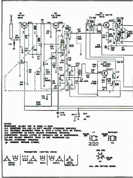
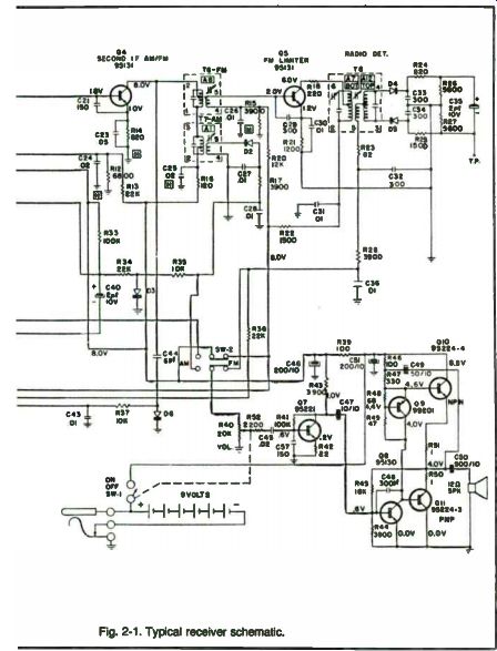
Fig. 2-1. Typical receiver schematic.
NOTES, RESISTANCE VALUES ARE IN OHMS 11.1000 ALL RESISTORS. AND 1/2 WATT UNLESS OTHERWISE SPECIFIED. ALL VOLTA«. MEASURED FROM 5- WITH A V.T.V.M. WITH NO SIGNAL. ALL CAPACITORS 25 VOLTS UNLESS OTHERWISE SPECIFIED. COLOR CAPACITANCE VALUES LISTED IN DECIMALS ARE IN MICROFXRADS, 50T le AND VALUES GREATER .TNAN 1.0 ARE PICOFARAOS UNLESS OTHERWISE SPECTRA.
COMMON (ROUND SIMIOS..
----------------------------
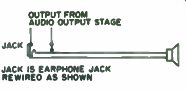
Fig. 2-2. Using the radio as a substitute speaker. You may wish to add a jack
as shown while retaining the original earphone jack on the unit.
Signal Tracer. The radio will work as several different tracers. The most obvious use is shown in Fig. 2-5A, an audio signal tracer. Injecting a signal at the detector as shown in Fig. 2-5B yields an rf demodulator tracer.
If you inject a signal into the i-f as shown in Fig. 2-5C, you have a 455 kHz tuned tracer (or 10.7 MHz if the radio has FM) for use with standard i-fs. If you allow disabling the oscillator as in Fig. 2-5D, you can inject another radio's oscillator signal to test the oscillator section of the other radio. Just inject the local oscillator from the radio being serviced, juggle the dial on both radios, and if you can pick up signals, the oscillator in the other radio is working. The same method could be used for FM systems. In that case, couple the oscillator signal to the FM converter stage through a gimmick of about seven twists of hook-up wire connected in the same place on the FM converter stage. You will have to add a switch to disable the oscillator as
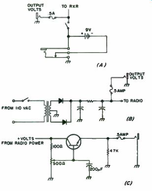
Fig. 2-3. Power supply circuits. (a) Simple battery supply. (b) Output is
taken from an ac supply. (c) Continuously variable output power supply.
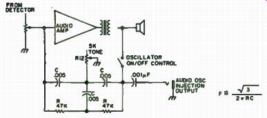
Fig. 2-4. Audio oscillator. May be used as an audio signal generator, code
practice oscillator, etc. Values shown are for approximately 1 kHz; use formula
for other frequencies.
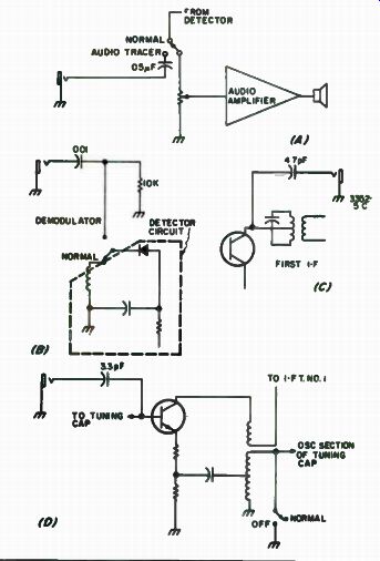
Fig. 2-5. Signal tracers. (a) Switch permits use as an audio signal tracer.
(b) The input is applied to the detector for use as a demodulator. ( c) 1-f
injection for 455 kHz. (d) Oscillator is disabled to allow injection of oscillator
from another set to test its operation. With switch at normal, radio can be
tuned to detect 1600kHz shown on the AM converter circuit. For the AM radio
the oscillator injection point also serves as a point to inject rf from a system
that uses 1600 kHz i-fs by letting the oscillator run and tuning the radio to
1600 kHz.
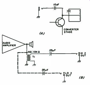
Fig. 2-6. Signal injectors. (A) The 455 kHz output from the converter can
be injected in various i-f stages to check out their operation. ( B) Addition
of an impedance matching transformer for an audio signal injector with high
output impedance. Dotted lines show alternate connection.
Signal Injector. The output of the converter taken from the point shown in Fig. 2-6A provides a 455 kHz signal for checking the i-f of a radio. An equivalent point on the FM converter provides 10.7 MHz signals.
Tune the radio to a station and the 455 kHz output will be the signal transmitted from that station. Figure 2-6B shows the connection for injecting audio signals; just tune in a station and use its audio to check out the audio circuits under test.
Alignment Generator. In Fig. 2-7 the output from the i-f is taken after it has gone through several stages of i-f amplification. Since this signal has the benefit of the several stages of selectivity, the i-f output signal can be used as a source of accurate 455 kHz (or 10.7 MHz) assuming the radio has been accurately aligned. Merely align the radio as one of the steps to making it into a piece of test equipment. Signals tuned in on the radio will be translated to their equivalent i-f frequency and can be used as alignment signals.
Transistor Checker. Figure 2-8 shows an outboard circuit added to the radio to allow in or out of circuit transistor checking. If the transistor under test will oscillate, it is generally good. This is a fairly accurate check in or out of circuit. Another simpler tester can be fabricated by merely replacing one of the transistors in the radio with a socket. When a transistor close to the type you are replacing it with is put in the socket, the radio should work. This test is only accurate for the NPN or PNP transistor type being replaced, and ...
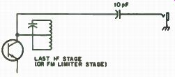
Fig. 2-7. This configuration will act as a fairly accurate i-f alignment generator
Since the output is from the last stage at the i-f, you have the advantage
of the narrowing from all the tuned circuits at the intermediate frequency.
... will only work with silicon or germanium types depending on what the radio had originally. This simple tester will not allow in-circuit checks at all, but the radio will operate normally as soon as the original transistor is placed in its socket.
Band Opening Monitor. Figure 2-9 shows the schematic of a citizens band converter that works into the 455 kHz i-f of an AM radio. You may shudder at the thought of listening to the citizens band, but it sure is a good band opening monitoring device. Just buy a crystal for channel 10 and you will rejoice when the DX comes rolling in. Crystals are available at your handy Radio Shack store for a few pennies. Just don't let them worry you with questions about what model transceiver the crystal is for ... any one will do.
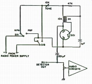
Fig. 2-8. Go-No Go transistor checker will work with silicon or germanium
types with reasonable HFEs. Use a good unit for checkout; if circuit fails
to oscillate, reverse either the primary or secondary connections.. A good
transistor will produce a tone in the speaker. You may wish to use clip leads
in place of a socket.
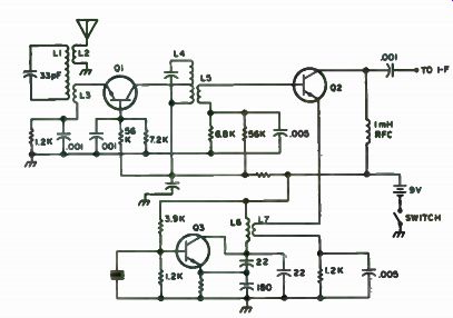
Fig. 2-9. CB converter for band opening monitor.
Commercial FM Receiver. If your radio has FM, it can be modified to make a receiver that will pick up commercial business-band FM signals such as police, fire, public service, weather, etc. Some find die idea of listening to these signals more appealing than music when th t radio is resting on the bench. Begin the modification by changing the oscillator coil. Reduce the number of turns by 1/2 , then bring it on frequency by adjusting the spacing of the turns and the trimmer capacitor on the radio. If you can't measure the oscillator frequency with a grid-dip meter or equivalent, use a TV tuned to channel 7. Watch the TV as you tune the oscillator; when you can see and hear a signal on the TV, the oscillator is set around 175 MHz. The radio will now tune around 185 MHz or 165 MHz, depending on the resonant frequency of the circuits in the rf amp and mixer stages. Reduce the number of turns in the rf stage and the mixer by the same factor as the oscillator coil.
Tune them in by adjusting the spacing and by resetting the trimmers on the tuning capacitor. Final tuneup should come while listening to a signal.
Now that the radio is completely modified, it will serve you well as a radio as well as a handy test jig ideal for servicing transistor radios. The unit is also perfect for the experimenter who may need to use one or all of its functions in checking out breadboard circuits. Once you master the use of all its possibilities, it will prove as handy on your bench as your VOM. World's Smallest Continuity Tester Using a rubber-type two-pronged plug, the few components that make up this tester are mounted inside the plug (Fig. 2-10). The hole in the end of the plug through which the cord enters is used for the NE-2 neon bulb.
Two small holes opposite each other are made near the base of the plug for the probe wires to extend, and the two 100k, 1/2 watt resistors within the ...
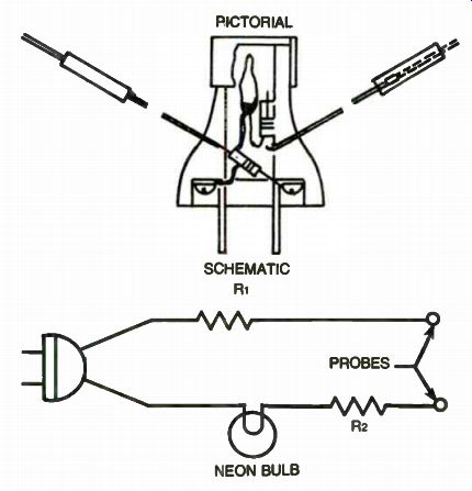
Fig. 2-10. Pictorial version and schematic.
... plug cavity, being in series with the probe cords, prevent shock. A piece of W' j. d. aluminum tubing 1/2 " long, placed over the bulb end of the plug, with a 5/8” o. d. clear plastic lens pressed into the tube, protects the bulb and enhances the appearance of the miniscule tester. Make the probe wires long enough to suit your needs.
Photo Electric Bench Accessory
Combine the leftover power supply from an experiment that failed with some 12 for a dollar CdS photocells purchased from S.D. Sales. Mix well with a lull in regular hobbyist activities and the result is an interesting unit with many uses.
The diagram in Fig. 2-11 shows the basic unit. The photocell is in series with a pot. There is a voltage applied across this series combination to ground. The op amp is used as nothing more than a high impedance driver for the one milimeter used as an indicator of relative light flux impinging on the cell. The word "relative" is important to note, as the meter is not calibrated in any special units. Its reading is comparative only and its function is to tell you that light has either increased or decreased at any specific moment. The ...
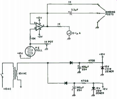
Fig 2-11. All resistor 1/2W.
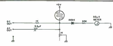
Fig. 2-13. Schematic.
... pot is used to control sensitivity. The higher the resistance, the greater the sensitivity of the unit. The photocell is mounted on two back to back lids from 35min film containers of the plastic variety. One film can makes up the body of the probe. This has a hole cut in the side to allow the cell leads to exit. Exiting the leads from the side rather than through the bottom allows the probe to be firmly positioned relative to a light source. A second container has its bottom cut off and is used for a stray light shield around the cell. These details are apparent in Fig. 2-12.
Notice that there are two outputs. One is DC coupled through an isolating resistor and the other is AC coupled through a 3.3 uF capacitor.
With the values indicated, here is an idea of sensitivity for general use.
An LED energized from an audio oscillator and held next to the cell will give about 1/2 volt of audio at the exciting frequency when the unit is at maximum sensitivity. This makes a handy bench coupler into your counter. A 60-watt bulb in a white glass shade will pin the meter from a distance of about 9 feet as will an ordinary two cell flashlight.
If you play around with QRP rf levels and are addicted to using pilot lamps as power indicators for tuneup, this unit will allow you to convert the light into a meter reading that seems much more sensitive to slight changes than the eye. When you are fighting for each milliwatt, this is very helpful.
The unit puts out a nice DC pulse with a flash of light hitting the cell.
Thus, the DC output can be used for triggering an SCR or used to bias the base of a transistor used as a switch or some form of DC amplifier for control purposes.
If you wish to raise the overall sensitivity of the unit, merely increase the value of the pot to 5k or 10k. This will greatly raise the sensitivity but ...
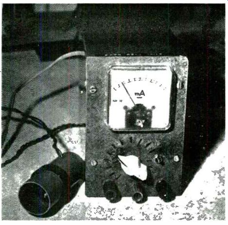
Fig. 2-12. Completed project.
... may' create stray light problems. For general use, the indicated values work very well.
There is nothing magic about the voltages shown for the op amp-six volts or so would work as well.
Note that there is no need to use shielded cable for the cell leads.
As with most projects, just about the time you get the last screw in place, there is that little voice whispering in your ear, saying, "I wonder what would happen if . . . 7" Well, this project is no exception. Figure 2-13 shows what happens when you listen to little voices.
The AC power supply has disappeared, replaced by two C cells in series. The op amp has vanished because a more sensitive (50 microamp) meter has been used. The diode in series with the meter is used to provide a hold-off threshold effect so a small steady meter reading is cancelled. Either unit does about the same job of providing your bench with a photocell dimension that will find many uses.
El Cheapo Signal Tracer
Every hobbyist needs a cheap signal tracer and audio amplifier at some time or another. If you try connecting a 117v AC to the audio output jack of a six meter receiver, you'll find you need one, too. Keep in mind that if you would try such a stunt, you'll have some painful memories.
One foolish experimenter tried this and when the smoke cleared, the two audio output transistors and their transformer were in such a mess that they were eligible for foreign aid (it's a Japanese receiver). Wanting to get back on the air fast, the hobbyist rummaged through the junk box until he found a cheap transistor radio. With this, a resistor, a capacitor and 10 minutes of work, he was back in business. Best of all, the transistor radio was still usable once the six meter receiver was fixed.
The modification to the pocket radio involves four steps.
• First, find the earphone jack and the earpiece and cord that plug into it. Inside, the jack will have three wires connected to it: a ground, a lead to the speaker and another one trailing off to the innards of the radio somewhere. This last wire actually goes to the secondary winding of the audio output transformer (Fig. 2-14). Leave the ground wire undisturbed. Unsolder the wire to the speaker and the one to the innards, both at the jack, and note which went where. Solder the ends of these two together and tape them.
Now the radio is permanently connected to its built-in speaker.
• The second step involves finding the point where the diode detector connects to the volume control. This can be found by tracing back from the center pin of the volume control along the foil until you find the glass diode. Unsolder the end of this volume control, but leave the other end connected. Solder a piece of insulated hookup wire to the free end of the diode. The other end of this wire is soldered to the pin on the earphone jack that was formerly connected to the...
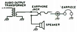
Fig. 2-14. The original circuit.
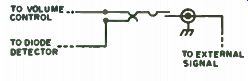
Fig. 2-15. The modified circuit.
...speaker. Solder another piece of insulated wire to the point on the circuit board where the free end of the diode used to be. The other end of this wire is connected to the remaining pin on the earphone jack that used to be connected to the innards. Now, without a plug in the earphone jack, the pocket radio will play normally since the diode detector is connected to the volume control once again, although now through the contacts of the earphone jack (Fig. 2-15).
• For the third step, cut the earpiece off the end of its cord. Strip the ends of the wires, and with an ohmmeter or continuity checker, find out which of the wires goes to the inner pin of the jack and mark it.
The other lead is the ground connection which can be connected to an alligator clip. Solder one lead of a 1 uF capacitor to the "hot" lead.
This capacitor will keep stray DC voltages out of your pocket radio, thus preventing premature trauma. The free end of the capacitor is the probe tip, and is to be connected to the equipment under test, wherever you suspect audio should be. With the earphone plug inserted in the jack, and the probe connected to the circuit under test, you should now hear the desired signal, rather than Olivia Newton-John. The lead with the capacitor can be built into the plastic end of a discarded ballpoint pen, to make a neater probe tip.
The voltage rating of this capacitor must be higher than any voltage you have in the equipment under test. For tube type receivers, 600 volts is usually adequate, while a 50 volt capacitor is adequate for transistor receivers and hi-fi gear.
If you're going to run the pocket radio from its own battery, this step may be omitted. If you would like to run the pocket radio from the voltage in the gear under test, this formula can be used to find the right value of dropping resistor:
Resistance= (Available Voltage) - (Voltage Needed) Receiver Current
For example, if your pocket radio needs 9v to operate, and 12v is available, and the pocket radio draws an average of about . 010a, then by plugging the numbers in:
12-9 / 0.01 = 3 / 0.01 = = 300 ohm resistance needed
The wattage needed for the resistor can be figured by the formula I^2 R = P; that is, the current multiplied by itself, times the resistance, gives the needed power rating in watts. In this example, it would be (0.1) x (. 01) x 300 = 0.03 watts. A 1/4 watt resistor would give a more than adequate safety margin. If you're planning to use a 150v supply to run the pocket radio, a 14.1 k-O at 1.4 watts is the calculated value, and 15k-ohm at 5 watts is adequate and a practical common value. This resistor is connected between the positive terminal of the battery holder and the supply voltage point, as shown in Fig. 2-16.
Fig. 2-16. Battery terminals with added dropping resistor.
Once completed, the pocket radio can be. used normally. By just plugging in the earphone plug/test probe, it becomes a signal tracer or audio amplifier. Total cost is less than 50 cents and you've still got your radio.
Test Instrument Saver
Delicate, costly test instruments may suffer severe damage when their conventional, too long leads snag on tools or on components spread out on the workbench and are inadvertently yanked off it to the floor.
A partial cure for this hazard is to replace the long leads with the much shorter coiled leads commonly used on cameras and flash units.
The coiled leads can be stretched out to where needed. When let go they retract out of harm's way. Should they lose their recoil power, rewinding the coils in the opposite direction helps restore their springiness.
Since each lead has two wires, their extra continuity gives them longer life.
The Violet and Other Houseplants Tester The device we are about to describe might be classified as a "one evening kit" and does just as the title says-it tests violets. Not only does it test violets, but other miscellaneous houseplants as well. This gadget detects the presence (or absence) of moisture and informs people when it is time to water their plants.
The violet tester does not require exotic memory ICs, clock chips or printed circuit boards. One LED (garden variety), a single 330 ohm resistor and a 9 volt transistor radio battery are all the parts needed for the heart of the device. The testing probe, case, etc., may be constructed of miscellaneous junk that you have accumulated.
If you will notice Fig. 2-17 the 9 volt transistor radio battery is in series with the 330 ohm resistor and LED indicator. The 330 ohm resistor limits the current to the LED. Without the current limiting resistor, the LED would draw excess current and soon destroy itself. Also in series with this are test probes. These probes, when inserted in the soil, will provide a current flow or complete the series circuit if moisture is present. The amount of moisture and mineral content of the soil will determine the current available to light the LED. Therefore, when adequate moisture is present, the LED will come up to near full brilliance. Varying lesser degrees of illumination will indicate less moisture.
At this point may we indicate that the violet tester is not a laboratory standard-it is merely a gadget in indicate relative moisture, and at that, serves its function well. What we are trying to say is-if some plant suddenly shrivels up, it is not the fault of the violet tester. On the other hand, if the vegetation involved suddenly tries to molest you some evening due to its fantastic state of health, it also is not the fault of the tester.
Anyway the device has proved to be much more sensitive than we had expected prior to construction. Common LEDs seem to be very responsive to minute current changes.
The moisture probe does not have to be a single chunk of copper tubing such as we have used. A pair of separate probes spaced 1" will work equally as well. The only requirement is that they be rigid enough to penetrate the soil.
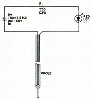
Fig. 2-17. Violet tester schematic.
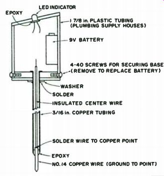
Fig. 2-18. Violet tester basic construction.
Figure 2-18 illustrates construction of the violet tester. We used a small chunk of 1-7/8" plastic water pipe to enclose the main circuitry. The top and bottom plates are made from scrap Vs" plastic. The top section (containing the LED) is cemented in place with epoxy. The bottom plate is held in place with 4-40 bolts. This allows the bottom to be removed for battery replacement. The 3/16' copper tubing probe must be made secure in the bottom plastic plate as it will take quite a bit of stress when being inserted in the soil.
A hole is drilled at the center of the plastic bottom plate just a bit larger than the 3/16" copper tube. A washer is then soldered about 1/2" down on the tubing. After inserting the tubing through the hole, the washer will limit its travel. Split the tubing that protrudes through the hole with a hacksaw and fold down the halves flush with the bottom plate. Epoxy cement the fold overs to the plastic bottom. The washer acts as the stress point.
Grind a piece of # 14 copper wire to a point and then solder a good length of insulated hookup wire to the non-pointed end. This assembly is then epoxied inside the 3/16" tubing. A small piece of masking tape wrapped around the center probe will hold it in place while the epoxy dries.
The LED indicator is also held in place in the upper plate with epoxy glue. After the glue has set, the wiring is completed. Use a battery clip for easy replacement of the 9v battery when necessary.
Just about everything in this device is non-critical yet good results may be expected. The layout and case may be just about anything that is convenient.
Not only may the violet tester be used for plants, but it should serve well as a lawn, rose bush or garden tester. By attaching clip leads and a remote probe, it would tell you when your basement is flooding. It makes a good continuity tester also. Just think, if some clever individuals were to mass produce this gadget, it would probably sell for $5.99 at local discount stores. Therefore, before this happens, you can be the first on your block with a violet tester.
After completing this "one evening kit" you might really have fun with the XYL by telling her it is a tester for the presence of coffee in a cup. If the tester is inserted in a cup of coffee it will indicate with full brilliance. With that, she will know for certain that you are completely "off your rocker" and really do need complete rest for six months in the Bahamas.
A $ 1 Strip Chart Recorder
In many instances a recording of a change against time can be of value in examining cause and effect. With recorders costing more than a 100 dollars, this advantage is not available to most amateurs.
This strip chart recorder, although of less than commercial stature, costs about ,a 'dollar and serves its purpose very well. It can be an interesting exercise in utilizing commonly possessed or available parts. The variations possible are myriad: direct clock motor drum drive, or through pulleys for mechanical reasons or to obtain the desired paper speed from an available motor. Similarly, the chart can be tensioned and paid off from its drum by simply attaching the loose end of the chart to a weight, or a more elaborate take-up may be devised by using another drum with an overriding rubber band slip clutch drive.
The choice in construction is facilitated by the wide range of drums available in practically every household-empty tin cans.
As an application example, a recorder is mounted above the main tuning dial of a receiver to record frequency deviations. The drum is an empty tomato can, 3 1/4 " diameter, overhung from a 1 rph clock motor shaft, giving a chart speed of 10"/hr. The tuning dial motion is carried to the recorder pen by a hacksaw blade, which is ideally springy in the line of the pen, while being quite rigid laterally. The recording is made by constantly adjusting the receiver for zero beat, if the strength varies. If the signal strength is constant, a preferred method is to tune for a constant "S" meter reading on the side of the band pass skirt. The chart is attached to the drum with tape and pre-wrapped about six times. The loose end of the chart hangs over the back of the receiver and table, and is weighted to take up the slack as the chart is paid off the recorder drum It is obvious that the receiver dial could be replaced by a variable resistor (pot) in a simple bridge circuit to record voltage or current. The XYL observes the bridge balance meter, preferably with a fixed magnifying glass and adjusts the dial on the resistor to hold the balance meter constant.
For convenience and a further exercise in applying junk box components, the bridge unbalance may be electrically sensed and used through an amplifier and small gear-motor to keep the bridge pot balanced and thus drive the recorder pen, as it is well known that many of the commercial recorders do.
The paper for the recorder may be cut from rolls of regular recording chart paper. If lines are not deemed necessary, plain paper or adding machine tape can be used. Pens can range from commercial recorder pens to fountain, ball or felt tip.
Build the Test Anything Tester
The little test instrument described here is something for the amateur who has nothing and something for the amateur who has everything. In the former case, it provides, very inexpensively, an instrument, that can function as a continuity tester, transistor tester, diode tester, signal injection source, code practice oscillator, CW monitor, substitution microphone and substitution loudspeaker. In the latter case, it provides a very handy addition to a tool box, for quick continuity and relative resistance checks, without having to look at a meter.
The instrument is nothing more than an audio oscillator using a one transistor circuit. But the components are carefully chosen. A switching scheme is utilized so that a low current is passed through the circuit under test. The volume and pitch varies with the resistance placed across its test terminals, and maximum utilization is made of the circuit and its components for several modes of operation. Such basic testers, but without all the versatility of the one described, have been available commercially for years.
They are popular with many service techniques, since one can visually concentrate on the circuit being tested or traced out without having to glance away to read a meter. This feature is particularly helpful when doing work on a detailed PC board, since one can lose one's place on the board in the time it takes to glance at a meter.
The circuit of the unit is shown in Fig. 2-19A. The oscillator circuit utilizes a transistor transformer, which has one or two center-tapped windings to form the equivalent of a transformer with three windings. One winding is used in the base circuit of the transistor, another as a, feedback winding in the collector circuit and another as an output-coupling winding.
Many of the usual miniature transistor transformers will work, aside from the TA-59 unit mentioned, such as the usual 10k ohm to 2k ohm CT or 1k ohm CT to 8 ohm units. One must be prepared to do a bit of experimenting to get the windings phased correctly and to get the output pitch desired. To achieve the latter with some transformers, it may be necessary to experiment with a small capacitor (0.001 to 0.1 uF) across the base winding. The output "loudspeaker" should ideally be a unit such as a 600 ohm telephone receiver. But anything, from high impedance, miniature loudspeakers to cheap, dynamic-type microphones, can be used. Power is supplied by two 1 1/2 volt batteries in series. No on/off switch is required, since no current can flow unless some resistance is placed across the test terminals.
The unit, as shown in Fig. 2-19A, can be used by itself, if desired. If the test leads are marked for polarity, one can test diodes and transistors and determine the direction of the junction involved. Resistance values, from a short to about 100k ohms, can be detected with the upper limit, depending on the specific oscillator components used. As the resistance value increases, the volume will decrease, but the pitch will tend to rise. This is a very handy feature, since, after a period of usage, one is not so aware of the volume changes as one is aware of associating higher pitch with higher ...
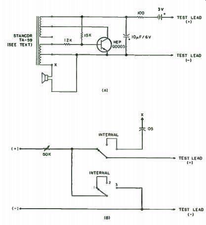
Fig. 2-19. Basic circuit of tester (a) and switching add-on for more versatility
(b). See text for description of components not marked.
...resistance. With usage, one can become familiar with the sound of at least the major steps in the output pitch, such as for resistance values of 1k and 50k.
By adding a few more components to the basic circuit, as shown in Fig. 2-19 B, more versatility can be gained from the unit. The addition of a series 50k potentiometer allows one to control the volume and also to limit the short circuit output current to less than 60 uA. The latter is useful as a safety feature, when testing some semiconductor devices, when one is unsure of the terminal markings. In the center position of the switch shown, the battery line is left floating and the positive test lead is connected to the speaker over a 0.05 uF capacitor. The speaker can then function as a replacement test speaker or as a dynamic microphone replacement. The reproduction quality is good enough to at least determine whether or not the speaker or microphone substituted for is basically defective. In the right hand position of the switch, the battery circuit is completed to ground, and the internal speaker output remains connected to the positive test lead. In this mode, the circuit functions as an injection oscillator, the level of which can be controlled by the 50k potentiometer and monitored on the internal speaker. The output is quite harmonically rich, and it can be used to check amplifiers all the way from the audio range to the HF range.
One switch that could be used is a special miniature DPDT toggle switch with a center position. But, in the center position, instead of the usual "off' position, the poles still remain connected to opposite side terminals of the switch. The switch is available for $1 from Tri-Tek, 6522 North 43rd Ave., Glendale AZ 85301. The switch can, of course, be replaced by a regular 2P3T rotary switch, but then requires a larger enclosure. Using the miniature toggle and with the basic circuit wired on perfboard, the unit is assembled in a 3 1/4" x 2 1/8 x 1 5/8” Bakelite box, complete with batteries.
Probably some more uses can be found for the circuit, with a bit of imagination and a modified switching scheme. For instance, it would seem possible to rearrange things so that the circuit could also function as either a preamplifier or a low level audio amplifier complete with speaker. All in all, it is hard to find a more handy unit for general circuit or equipment checking, before one resorts to proper instruments for specific checks.
--
Next: Voltmeters and Ammeters