Selecting a Frequency Counter
Thanks to microcircuits, there has been a major revolution in test equipment within the last few years. The prices of devices such as digital voltmeters, triggered sweep, oscilloscopes and others have dropped dramatically, a neat trick considering inflation! But more important, this excellent, low cost gear is getting into the hands of servicers and electronics enthusiasts where good equipment is both useful and necessary to cope with today's advanced products. The frequency counter has also benefitted from microcircuits and price cuts, but only recently has it begun to "take off" with electronic hobbyists and service people. This may be due to the past high prices, and a misunderstanding of what a frequency counter can do. But these things are going to change as more people are discovering what a counter can do for them! We are going to show you some of the things to look for when you shop for a counter, and some of the not-too-obvious pitfalls to avoid. There's a lot more than specs to consider, too-all counters have special features that may be obvious or not in the advertising literature. In short, we are going to try to make your selection a better one by showing the more important general features and explaining them, so you'll know what to look for.
Some of you skeptics are probably thinking, "Why do I need a counter?" A good question, indeed. Have you ever designed/built an oscillator and couldn't find the frequency? Then spent hours pruning the circuit to the proper frequency? A counter would tell you where you are at a glance. Or have you ever aligned a filter or trap or i-f stage and found that the center frequency was a city block off? A counter would help you keep tabs on the calibration of your signal generator and get a better alignment in the bargain! Have you ever had trouble accessing the local 2 meter repeater? A counter can tune up that tone generator in a jiffy. Ditto the transmitter with a VHF counter. Or, perhaps you are a CBer and people complain that you "bleed" on several channels. This could be caused by a sick transmitter with a bad crystal(s). A qualified technician can easily check this out with a good counter. Anybody still skeptical? Remember that you can do far more with a counter if you put your imagination to work! A Bit of History. You might be interested in how frequency counters evolved. The first method of frequency measurement eveed around the turn of the century when it was necessary to measure the frequency of radio transmitters. The gadget was called a wavemeter and it consisted of a paralleled coil, variable capacitor and spark gap (later replaced with a meter or light bulb). The capacitor had a calibrated dial, and it was adjusted until a spark appeared at the gap. The frequency was either read off the dial or extrapolated from a coil/capacitor chart if the dial read pFs. By the '30s, another form of frequency measurement came into vogue: the frequency meter. This unit had a built-in frequency standard and the unknown was mixed with it; the meter was adjusted until the signals "zero beated" in the headphones that were part of the unit. Old-timers will no doubt recall the BC-221 and LM frequency meters of WW II vintage with this mention-they were very famous! Digital electronics was the next development, and a digital frequency counter appeared in the early ' 50s. The first ones had 40-plus tubes, had neon lamps arranged in 0-9 columns for a readout, and were called EPUTs (Events Per Unit Time meters). The top frequency of those early counters was only a few MHz at most, although VHF range extenders appeared quickly. The early manufacturers were Berkley Scien tific and Hewlett-Packard. The next step was in the 60's when ICs became available. Counters became smaller and much cheaper, too. Many com panies are still using these warmed-over cicruit designs today, despite advances such as CMOS. Recently, one semiconductor company has intro duced a 2 chip counter, where all of the major parts of a six digit counter are on two LSI chips! Needless to say, the future has much to hold!
A Look at Basic Specs. Selecting the right counter takes some thought and an understanding of counter fundamentals. Without these things, you could end up with a three digit "toy" and have to align a generator that is 10 times more accurate, or a unit that is so versatile it does everything from makir.g the morning coffee (extra cost option) to checking a phono oscillator.
So, needless to say, the way to start is to sit down and analyze your own needs. Ask yourself such questions as, " What am I going to use a counter for?" and " What do I expect to be doing with my counter within a few years? These questions will help you decide the primary features that you must have in the counter you select.
For example, suppose you are an experimenter and you like to work with audio circuits and TTL logic. This suggests that you should start looking for a counter with a 20 MHz maximum range, because that is probably the highest frequency you are working with (frequency limit of standard TTL). Accuracy probably isn't critical to you and you might be able to settle for a unit that is 0.03 percent accurate.
Or perhaps you are a professional servicer and you are getting into CB repair. Your requirements are more strict. Since CB is 27.255 MHz maximum, you need one of the popular 30 HMz counters. Also, you need a counter that is 0.001 percent or " 10 parts per million" (abbreviated 10 ppm) accurate to satisfy FCC requirements.
Consider the future, too. If the experimenter upgrades to, say, CB, he'll need a faster counter. But there are devices such as prescalers to extend the range of counters at low cost. So, when the day arrives, he might only have to add a low cost black box to his counter.
On the other hand, if the servicer upgrades to commercial radio repair, he may have to replace the counter. Why? The frequency tolerance of commercial gear is often 0.0005 percent and that requires a counter of
0.00001 percent or 1 ppm. That spec is 10 times better than the old unit's! These are a few thoughts to keep in mind when you start your search for the right counter. Try to anticipate the future! Let's list the primary specs of a frequency counter and then discuss them. Note: They are not necessarily listed in order of importance.
• Accuracy
• Input sensitivity
• Minimum and maximum frequency range
• Display
• Power supply
• Special features or options
Accuracy. The accuracy of a frequency counter is determined by a quartz crystal or sometimes the AC power line (60 Hz). Fig. 10-1 shows a block diagram of a simple frequency counter. As you can see, the crystal/60 Hz is divided in frequency to operate the rest of the counter; this entire section is called the timebase. The timebase (or TB, for short) is the heart of the counter and its accuracy determines the accuracy of the counter. Price is also a function of the quality of this section. You'll find counters that use the 60 Hz line as a frequency element that sell for up to $ 150, and you'll see units that have crystals in ovens ( temperature stable enclosures) that sell for $6000 or more. The difference in accuracy is incredible: The 60 Hz TB counter will average 0.034 percent accuracy, the average accuracy of the 60 Hz coming out of the wall, to 0.0001 percent and better for the crystal oven unit! This is clearly one area where money talks. Typical counters run 0.005 percent (50 ppm) to 0.001 percent ( 10 ppm.) They use 4 MHz or 10 MHz crystals without ovens for low cost. These crystals are usually custom ground and the TB is carefully adjusted to get this degree of accuracy.
When you shop for a counter, try to get a counter with as much accuracy as you can to suit your needs. Remember you need at least a 10 ppm timebase for CB repair work, if that is your interest. The 60 Hz units...
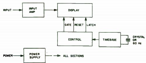
Fig. 10-1. Block diagram of a basic counter.
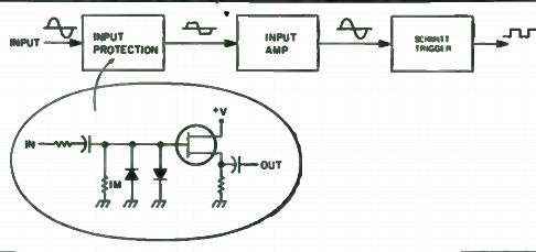
Fig. 10-2. Expanded drawing of input amplifier and a rough schematic of a
typical input circuit.
...are not for serious electronics work; 0.034 percent accuracy is terrible in the counter world. Anyhow, the few units available with these may be off the market by the time you read this! Input Sensitivity. Another sign of a counter's quality is the sensitivity it has to measure the frequency under question. Figure 10-1 shows an input amplifier, the section that has to do with the input sensitivity, and Fig. 10-2 shows a block diagram. The job of the input amplifier is simple: It amplifies the input signal and converts the signal to a corresponding set of pulses that is necessary to drive the counter's digital circuitry. The heart of the unit is the Schmitt trigger; it converts the incoming signal, which may be any kind of a waveform, into the necessary digital square wave. Generally, when you read input sensitivity specs, you must assume that the sensitivity refers to the minimum signal required at the maximum rated frequencies of the counter to get a steady reading. In other words, the specs are worst case.
Generally, the sensitivity of most counters in not flat over frequency, hence the min-signal-at-max-frequency bit. Figure 10-3 shows the sensitivity plot of the Gary Model 301 Counter, a 32 MHz unit. As you can see, the input sensitivity is not flat! But in this case, a non-flat sensitivity curve can work to your advantage. The high gain at audio frequencies allows use of devices such as microphones and magnetic pickups for organ tune-ups and tachometers. The lower gain at 32 MHz reduces the chance of overload by radio transmitters, too.
Typical input sensitivity is on the order of 10 mV to 120 mV for most counters. It is desirable to get a counter with slightly more than enough sensitivity to do the job. In most labs, 100 mV worst-case does fine.
You will also find a maximum input voltage spec on some units. This refers to the maximum voltage you can apply to the counter without dam age. This is always the peak AC signal plus any DC that may be present in the signal. For example, suppose you are measuring the signal of a homemade oscillator directly at the collector of the output transistor. You have, say, 9 volts DC at this point, plus, say, a 6v peak-to-peak signal: You are applying 9v DC + 3v peak or 12 volt worst case to your counter! Figure 10-4 illustrates this. This spec isn't really important to you unless you work around high voltage tube circuits and moderate to high power transmitters.
In this case, there are counters built with range switches (usually calibrated x 1, x10, x100, etc.) for use around high voltages. Typical maximum voltages are 20 to 100 volts for counters without range switches and 500 volts for the ones with them. These voltages are rated at a counter's maximum rated frequency, where the maximum input voltage must be reduced to prevent damage to the input amplifier. At low frequencies, such as 60 Hz, most counters will handle 120 V ac without problem.
Min/Max Frequency Range. This is probably the most advertised fea ture of frequency counters. Everywhere you look you are bombarded with ads screaming, "30 MHz Counter," "80 MHz Counter," "Or How About A 250 MHz Counter ..." and so on. Yet top frequency isn't all that important. A 30 MHz counter measures a 27 MHz signal as readily as an 80 MHz unit or even a 250 MHz unit or above. Yet, the price difference between these models can be at least several hundred dollars. All you are getting for the extra money of a faster counter is a unit with more capability. And that's fine if you sometimes need a counter to measure VHF signals; otherwise you can save money if you stick to a lower cost, lower frequency counter that will read the maximum frequency you expect to be working with. Remember, too, that low cost prescalers are available that divide the input signal by 10, so you can have your cake and eat it too! An often ignored spec is the minimum frequency a counter will display.
This depends upon the timebase and the sensitivity of the input amplifier. In order to get any accuracy from a counter when measuring slow signals, at least 10 Hz must be displayed on the standard MHz range switch set to kHz (actually 1 second gate time). Why? All counters have a built in ±1 count inaccuracy due to the circuitry. That's 10 percent of 10 Hz-in other words, your 10 Hz is 10 percent accurate! Also, TB errors show up in these digits, and can worsen or even improve accuracy at this point. The input amplifier sensitivity may drop at this point, too, making it hard to pick up low frequency signals. It's safe to say that the low frequency limit of most counters is 50 Hz for good accuracy (5x the minimum frequency is good test equipment practice) even though the counter will read lower frequencies. If ...
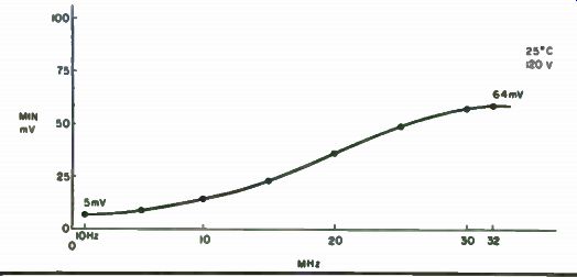
Fig. 10-3. Input sensitivity of a commercial counter. This plot shows the
minimum voltage required to get a stable reading on the counter.
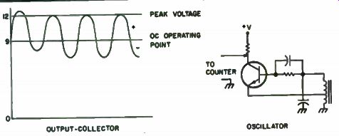
Fig. 10-4. Calculation of peak or worst case voltage that could appear across
a counter input. Note sample circuit.
... you do a great deal of measuring at low frequencies, you should consider a counter with a 10 second gate time, or a unit with a frequency multiplier, notably the Heath IB-1103. They will give you a display such as 60.1 Hz ( 10 sec TB) or 60.030 Hz (IB-1103). Display. The display on a counter can have a powerful bearing on whether you buy a certain model or pass it up. Important things here are the appearance of the digits and the number of them. LED type displays currently reign supreme in counters, so this is mostly what you'll see. Nixie tubes are seen in some older AC-only counters, but their use is dying out.
Liquid crystals show promise for the future, because they don't require the high current of LEDs and the high voltage of Nixies. When you shop, look for the largest and brightest display you can get, but do not let the appearance of the display bias your thinking. Accuracy and sensitivity are far more important in determining your choice.
The number of digits should be considered, also. As a rule of thumb, five to six digits are about the optimum number. Fewer (such as the three digits found on an inexpensive kit) require complicated range switching or more knob turning for you. And more digits can be confusing to read. Ever see 146.96 MHz read out on a large counter as 146960001 Hz? It's very confusing at times. Also, large digit counters consume larger amounts of power; consider that if you are buying an AC/battery model! Power Supply. Some counters offer you different ways to power themselves, often at no extra cost. The most common power source is 120 volts 60 Hz. You'll find many units that can be wired for 240 volts AC, but you may have to check the operator's manual to find this out. There are also counters that have 120v plus 12v DC connections. You can often plug them into a cigarette lighter for working on mobile electronics. A few battery operated counters are becoming available, but at present none have the full features of the other models.
Special Features/Options. A whole plethora of special features are available on counters. Switching ranges from a simple kHz/MHz switch to a full blown range switch of 0.01 ms to 10 sec. Inputs range from simple jacks to complicated attenuators and trigger level controls. Input impedances may be different, too. You'll find the standard 1 meg plus 10 to 50 pF input and a straight 50 ohm input (for VHF) on some units. Some of the more expensive units have timers/stopwatches and time interval measuring features built in.
And the list could go on. Base your selection on what features you really need and not what looks nice. It makes no sense to buy a $300 counter/ timer, then use the timer once and spend the rest of the time measuring frequency! Most options can be quite useful. Some popular options include frequency range extenders, high stability TBs, power cords, etc. Also, don't overlook good probes and cables. A x 10 scope probe is often used with the standard 1 meg input counter and will increase the maximum input voltage 10 times, preventing overload in most cases, and making connection to the equipment under test much easier. Needless to say, this is a very handy option and one that you should consider! If you feel that you must go for options, try to anticipate future needs. Sending a counter back to the manufacturer for modifications at a future date is usually much more expensive than ordering everything at the same time.
Some Pitfalls. Let's wrap this discussion of counters up by briefly mentioning some pitfalls that can trap you. Here are some of the areas to watch. Accuracy specs are sometimes hard to find on a counter data sheet, and when you do find them, they may not be complete! Although the data sheet may say "Accuracy: 10 ppm," nothing is said about the temperature or supply voltage, all of which affect the accuracy slightly, If accuracy is important to you and you are in this situation, it may pay to contact the manufacturer. Input amplifiers also have questionable areas. The input circuit of counters without attenuators should have an overvoltage protection network, usually diodes. Check. If the counter doesn't have one, avoid it or you'll be doing a lot of repair work on the counter! Finish up your evaluation by looking over the counter for any other features that you think will cause trouble.
If possible, try to get a "hands on" demonstration of the unit you select.
Make sure that everything works to your satisfaction, and that the counter lives up to your expectations.
A Fun Counter Project
The goal in designing this counter was to produce an inexpensive, no frills, reasonably accurate, minimum parts design.
High impedance FET input, . 2 to 30 MHz frequency range, sensitivity 60 mV RMS across most of its range, and compact packaging are some of its features. Also, two modes of timebase operation are possible: xtal controlled with an accuracy of ±20 PPM ±1 count and line frequency (± 0.05 percent). The heart of the counter (less readout and power supply) is mounted on 2 PC boards (=3" x 5"). The cost of the boards filled with parts (for line frequency operation) plus the six Minitron readouts will run you about $40. An additional $8 pays for the xtal controlled timebase, and of course you'll need a power supply. Any junk box parts substitute will naturally reduce your costs.
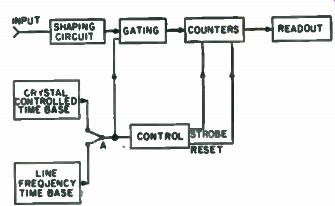
Fig. 10-5. Block diagram.
Operation. The block diagram of Fig. 10-5 shows the signal flow and control. Referring to Fig. 10-6, Q1 to Q4 shape the incoming signal to produce TTL compatible levels. A precise 100 ms gate (at IC19 pin 2) is then ored together with the signal (IC19 pin 3). This gated signal is counted down and displayed on the readouts. The trailing edge of the 100 ms gate triggers the one shot IC24. A pulse is generated that strobes the quad latches IC7 to IC12. The stored data is transferred to the decoders and readouts. The trailing edge of the one shot triggers another one shot IC25 to produce the reset pulse to counters IC13 to 18. All counters are reset to zero until the next gated input is counted. Thus the sequence is: gate, count, transfer, reset.
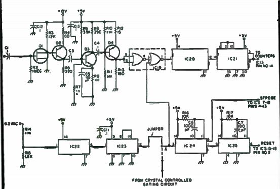
Fig. 10-6. Input and Control board.
Construction. As mentioned earlier, the heart of the counter is mounted on 3" x 5" PC boards (actually 3" x 5-3/16"). You can package these boards any way you like. Just allow sufficient ventilation in any enclosure you use.
One of the drawbacks of laying out small boards is that you can't get all the circuit connections on them that you'd like. So we're going to have to add some jumpers. Refer to Figs. 10-6, through 10-8. After all the components
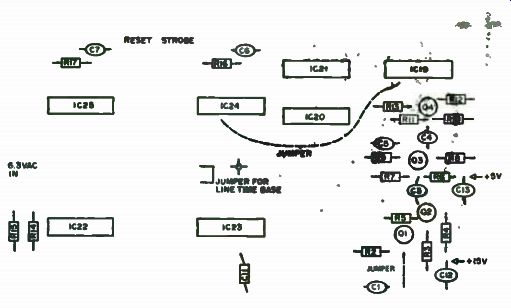
Fig. 10-7. Component layout, Input and control board.
... are mounted, jumper IC19 pin 2 to IC24 pin 3. Also jumper point "A" to the pad right above it (for line base operation). That's all the jumping we need for the Input and Control board.
The Readout board will require the following jumpers (Fig. s 10-9 through 10-11):
• IC7 to 12-jumper all pins 4 and 13 (strobe).
• IC13 to 18-jumper all pins 2 (reset).
• IC13 to 18-jumper pins 1 and 12 on each IC only.
• IC13 pin 11 to IC14 pin 14.
• IC14 pin 11 to IC15 pin 14.
• IC15 pin 11 to IC16 pin 14.
• IC16 pin 11 to IC pin 14.
• IC17 pin 11 to IC18 pin 14.
Also, power to all ICs and all power grounds will have to be added.
Refer to Fig. 10-9. Jumper grounds to the ground plane and between boards.
Use Molex terminals to mount all ICs. The added cost is worth it.
The Input and Control board artwork (Fig. 10-8) is laid out for 60 Hz operation. If you're satisfied with an accuracy of approximately 500 PPM on your counter, use it as is. You won't need the LM340-5T in the power supply, so that's an additional saving.
The crystal controlled timebase should be added to get the most accuracy from your counter. Figure 10-12 is a suggested circuit. There is no artwork included for this additional circuitry. Layout is not critical and could be hand-wired in no time. If used, you won't need IC22 and IC23. To connect, remove the jumper at point "A" and connect the output on the last counter to point "A". That's about it. If you got all the jumpers in right and your power is connected right (double check), you should be finished.
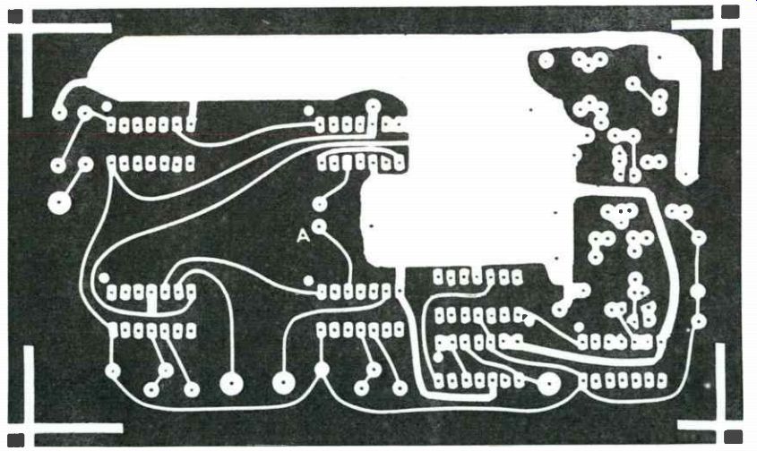
Fig. 10-8
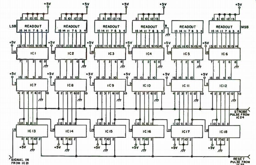
Fig. 10-9. Display board.
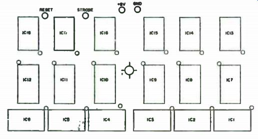
Fig. 10-10. Component layout, Display board.
For a final check, make sure all ICs are installed correctly. That's another reason for using the Molex terminals. It's a lot easier to reverse an incorrectly mounted IC with them.
There is no calibration procedure. It it's wired right, it'll work. One work of caution. If the counter fails to count all the way up to 30 MHz, IC21 could be the cause. It has to divide by 5 up to 15MHz. Substitute it with other 7490s until you get one that goes to 30 MHz on the input.
Finally, your counter is compatible with any of the prescalers available on the market, extending its range to 300 MHz. For a complete parts list, refer to Table 10-1.
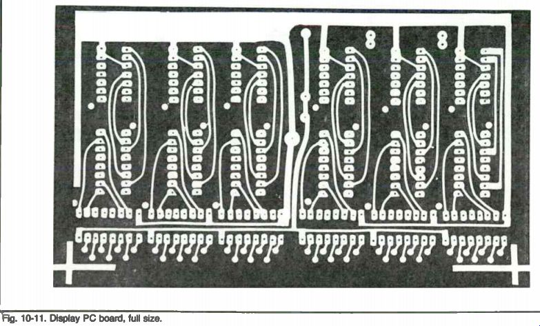
Fig. 10-11
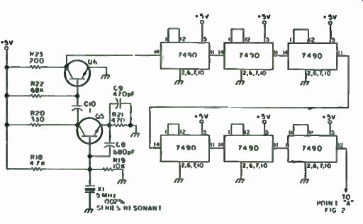
Fig. 10-12. Crystal controlled timebase.
----------
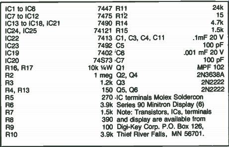
Table 10-1. Parts List.
IC1 to IC6 7447 R11 24k IC7 to IC12 7475 R12 15 IC13 to IC18, IC21 7490 R14 4.7k IC24, IC25 74121 R15 1.5k IC22 7413 C1, C3, C4, C11 .1mF 20 V IC23 7492 C5 100 pF IC19 7402 C6 .001 mF 20 V IC20 74S73 C7 100 pF R16, R17 10k 1/4W Q1 MPF 102 R2 1 meg 02, 04 2N3638A R3 1.2k 03 2N2222 R4, R13 150 05, Q6 2N2222 R5 270 • IC terminals Molex Soldercon R6 3.9k Series 90 Minitron Display (6)
R7 1.5k Note: Transistors, ICs, terminals R8 390 and display are available from R9 100
Digi-Key Corp. P.O. Box 126, R10 3.9k Thief River Falls, MN 56701.
-----------------------
A $50 Self- Powered Counter
To you this may look like another construction project. "A pretty neat little counter," you'll say. "Think I'll build one." Little will you know how long it took to get the bugs out and keep the cost down. This project is the pinnacle of savings. It is a 6-digit (that reads out to a full 8-digit capacity) counter, portable, hand-held, sensitive, rugged, LED readouts, requires no test equipment to build, and more, all for just a little over $50. Costs are sliced down to an absolute minimum by cutting all the frills.
For instance, many counters advertise no-flicker, or non-blinking readout.
This one blinks, but you can only see it on the lowest reading scale, when you are reading signals to 1 Hz. The rest of the time the digits blink for 1 ms, and when was the last time you could see a 1 ms blink? Most hobbyists will use the MHz and kHz scales most of the time anyway so the "blink" will be for 10 us and 1 ms respectively. And, when you are showing the XYL or neighbor your latest creation, show them on the Hz range so they will be impressed by the blinking, counting readouts! While cutting out the non-blinking feature does save some money, the greatest saver is cutting out 3 of the 6 digits! I know, you are wondering how it is that we get a 6-digit counter with 3 of the digits missing. At current prices, dropping 3 unnecessary digits saves nearly $25. Even at TWS a 3 DCU costs $ 18. So if you can liberate an extra $ 18 for this project, you can have all 6 digits! But it is all the more fun to drop 3 digits, build the unit in half the width and shift the readouts around to get a look at 8 digits of the incoming signal. Even in a 6-digit counter you have to shift the range switch around to get readout of say a 14.85 MHz signal to the nearest 1 Hz! With the handi-counter you have just one more shift to get the same capability with only 3 digits!
The basic "brains" for the counter come order a digital dial kit from TWS Labs, PO Box 357, Provo, UT 84601 for $45.95. When you order the digital dial, you get the same stuff you would get if you order the individual kit (a 3 DCU and a timebase), but you get a free AC power supply in addition. In fact, you can power your unit from this supply if you don't want to add nicads like in this version of the handi-counter. Or you can keep the power supply and have a good source of fairly well regulated 5v DC for your workbench.
The fact that the basic counter comes in kit form makes this project all the easier. All you need to do is make some very simple modifications to the kit, add the digit switching circuit, a couple of extra circuits on perfboard and you have an instant 3 x 6 digit counter! Operation. Let's look at how you use the unit before you build it.
Actually, the principle of operation is very simple. There are several front panel controls. First is the on/off switch-a simple enough function. Second is the MHz/kHz selector (both these switches come with the kit); this one selects timebases and does some decimal point selection. We could have labeled it Hz/kHz like its 6-digit brothers; it would only have required putting the decimal points in some other places that were not convenient (and cheap) with this kit.
The third switch, the one in the middle of the panel, we can call the "display selector" switch. This one comes from your corner Radio Shack and is p/n275-405, a 4 PDT switch that currently is priced 69 cents . Other than the box and batteries, this is the only expenditure that is not available in a kit.
You could have a complete counter that would only read to 100 Hz so far.
Back to the 4 PDT switch. It is used to select which 3 digits of the 6 available digits are viewed at any one time. When you throw the switch to the left, you see the left most significant digits and to the right, you see the 3 right most significant. The decimal point jumps around every time to keep you thinking straight. Figure 10-13 shows how it works. For an example, we used a 40 meter signal that is actually 7,224,362 Hz. This is how the counter sees it: Note the placement of the decimal point; also note that in kHz left and MHz right, the readout is the same, but the decimal point is shifted. That is because, if you look at the original signal you can see that there are: 7.2 MHz, . 224 MHz or 224 kHz (see, the readout means the same thing) and finally . 362 kHz. That last 0.362 kHz is the same as 362 Hz, but would demand another timebase switch position, so we merely switch a decimal point and call it a fraction of a kHz.
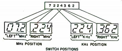
Fig. 10-13. Here is how the digital display in the Handi-Counter shows the
eight complete digits in this forty meter signal. You simply move the digital
display around and "look" at different portions of the signal at
selected times. MHz POSITION KHz POSITION; SWITCH POSITIONS
Suppose you hook the sensitive input circuit of the counter to an oscillator you built. You want a look at the output frequency of the oscillator.
Maybe you see 21.8 on the MHz left setup; that means the oscillator is running at 21.8 MHz. If you were only interested in roughly knowing the MHz range of the oscillator, you would stop right there. If you wanted the kHz range you would leave the display left, and throw the timebase selector to kHz. That would give you a frequency check to the nearest kHz. Suppose you wanted further accuracy, or to know how much it drifts; then flip to the right digit display (still in kHz) and read out in Hz. You can see the flexibility of the whole thing! You have 3 digits in a lot smaller package, for a lot less cost and you are reading a 21 MHz signal out to eight places! Figure 10-14 is the block diagram of the counter and this will help you understand what is going on in there. The easiest process takes place in the kHz position. Here, the timebase selector and display selector switches choose to provide a one second (right) or a 1 ms (left) signal. This is high-accuracy stuff with the timebase being divided by a million to get the one second clock; any errors or drift in the timebase oscillator (already crystal-controlled) are divided by the million too. At the very beginning of the count time ( 1 sec or 1 ms), the timebase gives a reset pulse that starts the counter stages at 000. Then the counter merely counts the input pulses that occur during the selected time period. On the kHz left position, for example, the counter is cleared and enabled for one second. When counting a 60 Hz line input, the counter would start to flash (the part that will impress the average observer) until the end of the counting cycle when it will sit there displaying 0.060 kHz, or 60 Hz.
When the display selector switch is pushed left, we apply a 1 ms gating signal to the counters and count the events that occur in 1 ms, or in other words, we count kHz. A 30 kHz signal will show up as 030. Note that there is no decimal point. There is no need, as the timebase selector is in the kHz position so it reads out as a whole number, not a decimal fraction. From the block diagram, when one switches to the MHz range, the clock now comes from 1 ms and 10 us. The 10 us clock is fed to the counter circuits in the "MHz left" position and merely allows the counter stages to count for 10 u-s.
On this scale, the chance for error from the 1 MHz crystal is greater and the fact that the timebase is crystal-controlled becomes the greatest asset. At the 10 us point the clock signal is only divided by 10. With 10 us gating the counter can count up to 99.9 MHz; in real life the limit is imposed by the fact that the counter circuits will only operate to 30-40 MHz without a prescaler.
Since most prescalers divide the display by ten, you will display MHz on all three digits, so the decimal point can be left out.
It is probably a good idea to explain why there is a different reset circuit than the one with the kit. The reset circuit with the kit is designed to give high accuracy with fast input signals and operate at a 10 ms and 1 ms gating output. While the kit's reset is more accurate than the "extra one" built for the handi-counter, it causes some problems while running at slow speeds.
The reset actually resets a couple of clock pulses before the gating signal enables the counter. That works great at 1 ms and 10 ms and means that you are not depending on the characteristics of the input impedance of a gate and some resistors and capacitors for your reset pulse; the pulse is clock controlled. The trouble comes when the clock is one second. The strobe circuit causes the counter to sample the input signal every second and a half or so and you can extend it to a few seconds by increasing the size of the timing capacitor in the unijunction oscillator circuit. Well, at one second clock speed, the counter resets to 000, waits a couple of clock pulses (seconds), then enables the counter stage and the stages count the input signal. After the one second counting period, it is time for another sample and the display resets again. The result is you don't have the display lit long enough with the number to even read it. You may choose to merely extend the sample time by putting more capacitance in parallel with the timing capacitor (33/4E) in the unijunction circuit that comes with the kit, or you may use the reset circuit shown here.
The reset circuit built for the handi-counter works like this: When the enable signal goes active to allow the counter to count the input signal, a very fast RC differentiating network creates a narrow spike that resets the...
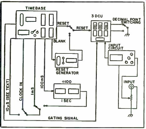
Fig. 10-14. This is the block diagram of the unit showing some of the switching
that is accomplished with only two switches in the unit, a DPDT that comes
with the timebase kit and an "added" 4 PDT.
... stages. You can see that since this spike occurs because of the enable signal, it actually resets the circuits when they are supposed to be counting. This is no real problem at slow speeds, but at higher speeds, if the reset pulse is very wide, it can knock off a pulse or two and give an inaccurate reading. For the 10 us signal knocking a few pulses off can throw the MHz readout way off. In most counters that use this method, they merely adjust the clock signal so that the counters are enabled a little longer, but few of those counters use a gating signal of only 10 us, so that's why we have the two reset signals.
The counter input amplifier shown is pretty sensitive. It works well just picking rf up with a little wire antenna. Its major problem is that you can blow the FET pretty easily. So be careful about input signals.
To calibrate the counter you can use a known accurate signal, or beat the oscillator against WWV. Construction. Building the counter is really not hard. Obviously, the first step is to collect all the parts, then do the layout of the front panel of the case, and finally, mount the pieces in the box. You can use any box for your counter. The key to switch mounting is to keep the switches out of the way of the 3 DCU and timebase circuit boards. The input jack and the sensitivity control are mounted on top of the case. You will probably want a jack for charging your nicads without removing the cover from the box. If you decide to make your unit nonbattery-powered, you will still have a lot of room in the box because all the power supply components mount on the top of the timebase PC board, and the transformer is small enough to sit on the bottom of the case.
Mounting Batteries. The bottom of this hobbyist's box wasn't flat; it had some design raised in there, presumably to add strength. This was a problem in mounting the batteries and he ended up being able to get only one bolt through each holder and that only thumb tight. That only allows the batteries to stay in place, and offers very little strength against drooping, etc. The batteries are mounted to leave a "cavity" so the crystal, which sticks into the case pretty far, has room to keep from getting crushed. This cavity also makes a convenient place to put the three external circuit boards.
The battery mounting bolt leads stick out of the bottom of the case to mess up the effect of the little "feet" on the box. It is easy enough to glue flat grommets to the bottom, with the hole over the bolt heads for better feet than were on the box in the first place. Note: Later experiments showed that it is easier to buy a plastic 4-C cell holder and use it. The holder mounts in a smaller space than the individual cell holders and there is plenty of room for the crystal and external circuits. An added benefit is that the holder is cheaper than four of the individual units.
Building the Circuits. It is easy to build the kits; all the instructions are included. Trim leads very close to the PC boards. While the kit instructions do not stress this, we are going to mount the PC boards back-to-back under some pressure and we don't want any extra long or sharp leads sticking out of the boards. Even trim the leads on the crystal. They don't mention it in the kit, but it helps in sandwiching the boards closer together. Also take care in ...
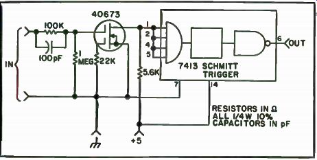
Fig. 10-15. Schematic diagram of the input circuit used with the Handi-Counter.
... running the external wires on the board. They should be laid out so that they do not cross any pins or leads on the back of the board. Under pressure, these can puncture the insulation on the wires and cause a short. If you are using a different physical approach and have plenty of depth in your box, use the mounting method described with the kits and you eliminate many of the aforementioned problems.
Building the Input Circuit. The input circuit is built on a phenolic board, although you can make a tiny PC board for it if you want. Or, if space is at a premium, you can get the timebase extender board that comes in kit form from TWS; it is roughly 2" x 3" and has all three of the external circuits right on the one board. It was mounted near the input selector switch, while in the final version, longer wires were added and it fit in the cavity formed by the batteries, and near the input level control and input jack. Make sure your wires are long enough hookup wire with the kit for most installations. After the circuit is built, put some tape on the bottom of the board so the circuit will ...
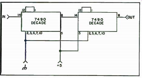
Fig. 10-16. Schematic diagram of the divide by 100, one second extender circuit.
This circuit allows the counter to look at signals in the hundreds of cycles range and provides readout to 1 Hz.
... not touch the battery holders or the other circuits that are stuffed along with it in the battery cavity. Figure 10-15 is the schematic of the input circuit.
Divide by 100, Extender Circuit. The 10 ms clock from the kit drives this circuit shown in Fig. 10-16. The output of the divide by 100 circuit is one second clock used in the timebase generator to make the one second enable signal for the counter. The circuit is very simple, and consists only of two decade dividers in series.
Reset Generator. The reset generator is very simple; it consists of the RC network and a 7400 gate used as an inverter. Figure 10-17 is the schematic of the circuit. The output of the gate is a normal logic 0. When the sample signal comes along (actually the inverse of the signal called the blanking signal with the kit), it causes a positive pulse output and resets the counter stages. Because of the nature of this reset, as mentioned before, it is best not to use it (use " kHz left") when looking at very fast signals. On slower signals, there will be no difference in reading between this and the "MHz right" readings.
Interconnecting the Circuits. Figure 10-18 shows the major interconnections and the hookup of the input circuit. First mount the 3 DCU counting and display unit on the front panel. Then run the power and interconnections as given in Fig. 10-18. Run 1" wires from the terminals on the 3 DCU card.
These will connect later to the switch and the timebase board. Run the decimal point wiring to the switches on the front panel as shown in Fig. 10-19.
Figure 10-20 shows how to connect the reset circuit to the timebase and 3 DCU boards. Figure 10-21 shows the hookup for the interconnecting wiring that does the timebase switching, including the divide by 100 circuit.
When the wiring is completed, put an insulating card (a piece of 3" x 5" file card works great) between the 3 DCU and the timebase card. First mount the whole thing up and tighten down the mounting bolts. Then take the thing apart again and inspect the piece of card for punctures where a wire from the circuit board was too long or too sharp. Trim the faulty wires or pins, reinforce the card with a black electrical tape strip around the puncture (if any), add another layer of insulating card, and remount the boards.
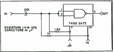
Fig. 10-17. Reset generator schematic. This added circuit provides a reset
for the counter in the low speed ( 1 Hz) readout position.
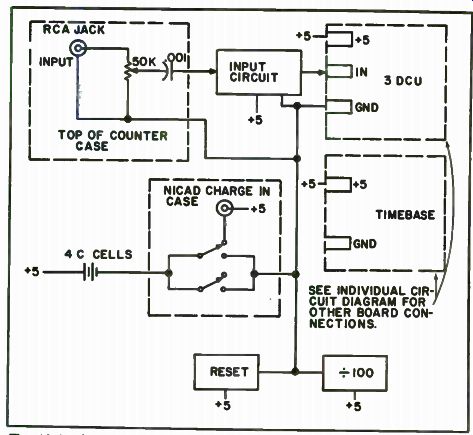
Fig. 10-18. Major power hookups and input circuit hookup. Note the nicad charging
circuit. With a power supply ( charger) plugged in, the nicads will charge
when the unit is off. You may wish to allow them to charge at all times. If
you use the power supply supplied with TW's kit, you turn the unit on and off
by cutting the ac from the ac cord to the transformer input.
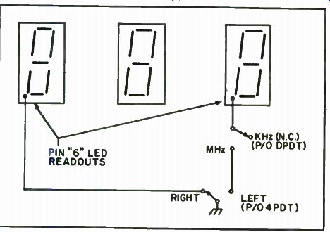
Fig. 10-19. Decimal point wiring diagram.
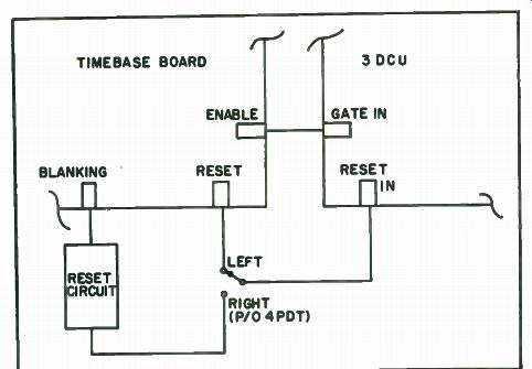
Fig. 10-20 Reset circuit hookup to the timebase and 3 DCU boards.
Put in the batteries, drop the input circuit, divide by 100 and the reset circuit boards in the cavity. Don't forget to install the input jack and pot. Wire the power connections to the batteries. The displays should light.
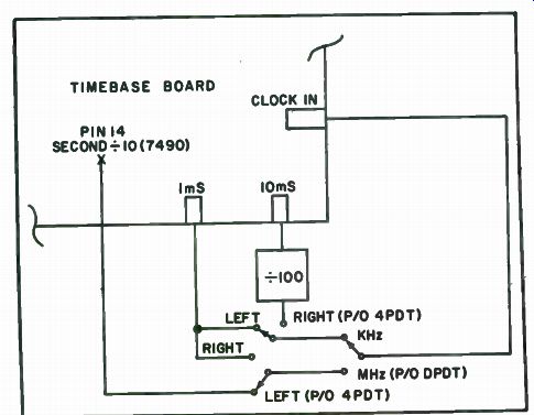
Fig. 10-21. Timebase switching diagram. Note that 1 ms is used on both MHz
right and kHz left. The difference is the decimal point, and the source of
reset pulse. ( See other figures for details.)
Checkout. When power is applied, the readouts may show any number reading at all. This is normal. After a second or two, when the oscillator is running and all the circuits settle, the random numbers should clear. The display should flash "000." Now you are ready to use your counter and look for all manner of signal. Make sure the thing resets in all switch positions and you can tell if your new reset circuit is working properly.
Points to Remember. The unit will only run for a couple of hours from fully charged nicads, so don't leave it sitting around "power on" unless you are using it. The crystal oscillator is extremely stable and will work with little or no warm-up so don't worry about leaving the power on. Build a nicad charger and keep the nicads fresh. Some will want a trickle charger that will always keep the unit "ready to go." You may want to build up the power supply external to the unit, let it trickle the nicads (there is 8v unregulated in there). You can also use cigarette lighter power by using a suitable dropping resistor. For that purpose, it is possible to use the regulator circuit and either positive or negative ground 12 volts. Instructions for mobiling come with the kit.
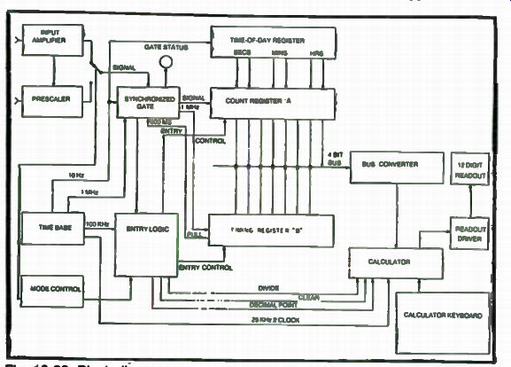
Fig. 10-22. Block diagram.
The Calculating Counter
Traditional counters provide very limited resolution of audio frequencies associated, for example, with organ and piano tuning. The usual one second gate time yields a reading varying between "59" and "61" for 60 Hz.
To determine this frequency with any accuracy, you must measure the period of one cycle ( 16,666 microseconds), reach for your handy pocket calculator, and calculate the reciprocal (or wait 100 seconds perhaps!). We decided to explore the possibility of teaching a counter to calculate frequencies from period measurements. It soon became apparent that designing a circuit to calculate reciprocals was no simple task. A ready-made solution to this dilemma presented itself in one of the "calculator chips" widely advertised at attractive prices. The "One-Chip Calculator" advertised as a type 5001 turned out to be both inexpensive and practical. The chip comes in one of two voltage ratings (for desk or pocket calculator use). While we used the low voltage model, which requires - 8.5 and - 13.5 volt power supplies, the higher voltage unit should be directly interchangeable, with minor power supply modifications.
We wished to construct an all-purpose counter, and our final design includes a basic 30 MHz counter, a high frequency prescaler, a reciprocal calculator, a desk calculator, a digital clock, an interval timer and an incident counter. All logic circuits are TTL, except for the MOS calculator chip and ECL prescaler. Discrete devices are used for TTL/MOS interfacing and for driving readouts.
Design, construction and debugging of a project of this magnitude is virtually impossible without a test-breadboard facility. It is necessary to breadboard each function, and test it in turn. A suitable power supply is also essential, and we recommend construction of the power supply first, but note that use of different readouts or other components may require modification of the power supply.
Theory of Operation. Overall data and logic flow may be followed by reference to Fig. 10-22. The frequency to be counted is connected either to the input amplifier (high impedance) or directly into the prescaler (50 ohms). The prescaler is automatically activated in the MHz mode. Note that the high impedance input may be used in all count modes, and it provides good sensitivity through the two meter band.
The synchronized input gate directs input pulses to register A, an 8 digit decade counter, and timing pulses to register B, a 6 1/2 digit counter.
Gate time in kHz and MHz modes is one second (plus or minus one input pulse period), and in the Hz mode varies between 800 milliseconds and two seconds (800 milliseconds plus one input pulse period). When the input gate doses, entry logic is enabled, and in the kHz or MHz modes, the contents of register "A" are entered serially into the calculator, which displays the entry just as if it had been made from the keyboard. In the Hz mode, the contents of register "A" are entered, trailing zeros are padded to improve resolution and the "divide" function again activated. This sequence causes the number of input pulses stored in register "A" to be divided by the number of timing pulses stored in register "B". The result (with the decimal point appropriately positioned) yields the frequency of the input (with up to four decimal places!). The bus converter interfaces the TTL registers with the MOS calculator, and changes the BCD coding of the TTL to conform to the 5001 chip's requirements.
The time-of-day register constantly contains the time, updated each second. Register "A" utilizes decade counters with preset inputs. In the time-of-day mode, once each second, the contents of the time-of-day register are strobed in parallel into register "A" and then serially entered into the calculator as in the kHz mode.
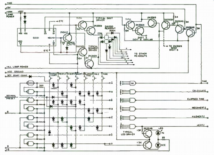
Fig. 10-23. Readouts and Mode Switching. The neg. light is the G-segment of
the left-most readout.
The accumulate and period modes cause the input gate to be controlled either manually or externally, and either timing or input pulses are routed to register "A" as appropriate.
Readouts. Selection of readouts is guided by desired digit size, price, availability, power supply and driving requirements. Readouts for use with the 5001 chip must have decimal points to the right of the digit.
Various readouts are suitable for use with calculator chips. The wide array of LED devices available suggests these would be preferred. Most calculator chips utilize multiplexed readouts, where like-segments of all digits are connected to a common bus line. Each digit is selected (turned on) for a brief period in turn. This driving method reduces wiring and driving hardware, because only eight segment drivers (including the decimal point) and one digit driver per digit are required.
LED readouts may be driven by the newly available 75491 and 75492 Darlington driver arrays; however, as they are NPN devices, PNP pre-drivers may be required. Drivers shown in Fig. 10-23 are also suitable for driving LEDs, with the addition of limiting resistors.
Incandescent readouts require drivers capable of handling substantial inrush currents. Digit drivers should be selected to handle 500 mA. The author's choice of incandescent readouts was influenced by cost at the time, and size of display. Present LED prices make them much more attractive.
Selection of the 2N3569 for drivers was influenced by our junkbox stock, but the 2N2905 (PNP) is probably more suitable. The calculator data sheet shows PNP drivers, and use of the 2N3569 (NPN) requires the circuits of Fig. 10-23 to make the NPNs think they are PNPs. Diodes are required for isolation between each segment and the segment bus.
Table 10-2. Calculate/Count Program.

----------------
Count Mode-khz
Decimal Point Preset at "3"
1. Open Input Gate
2. Close Input Gate ( 1 second later)
3. Clear Display ( CE) A. Enter 5 High Order Digits From Register "A"
5. Enter Decimal Point
6. Enter 3 Low Order Digits From Register "A"
7. Clear Registers Count Nods-MHz Decimal Point Preset at "3" Prepsler Activated
1. Open Input Gate
2. Close Input Gate ( 1 second later)
3. Clear Display ( CE)
4. Enter 6 High Order Digits From Register "A"
5. Enter Decimal Point
6. Enter 2 Low Order Digits From Register "A"
7. Clear Registers Cling Moda-Hz
1. Open Input Gate
2. Open Clock ( Register "B") Gate
3. Close Input Gate ( When Register " B" Full)
4. Close Clock Gate
5. Clear Display ( CE)
6. Enter 8 Digits From Register "A"
7. Enter Three Zeroes
8. Enter " Divide" Command
9. Enter 4 High Order Digits From Register "El -
10. Enter Decimal Point
11. Enter 3 Low Order Digits From Register "8"
12. Enter "Equals" (" Divide") Command
13. Clear Registers (Delay New Count Cycle to Provide 2 Second Update)
Elapsed Time Mode Route Clock ( MS or uS) Pulses to Register " A' (gated)
Route Input to Control Input Gate Update Once Each Second Clear Register -A-
1. Clear Display ( CE) 2 Enter 5 High Order Digits From Register "A 3 Enter Decimal Point
4. Enter 3 Low Order Digits From Register "A Accumulate Count Mode Route Input Pulses to Register -A Update Once Each Second Clear Register "A 1 Clear Display ( CE) 2 Enter 8 Digits From Register A - Time-of-day Mode Blank 2 Digits Update Once Each Second 1 Clear Display
2. Load Register "A • Time-of-day Register
3. Enter 8 Digits From Register " A • Calculate Mode Lock Out Data Entry Sequencer (Keyboard Always Live)
Continuous Count Mode (Hz, kHz. MHz)
Enable Automatic Count Restan ( input gate)
on Register Clear Siva' Single Count Mode (Hz, kHz, MHz)
Manual Count Restart ( input gate)
--------------------
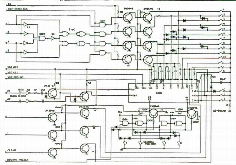
Fig. 10-24. Calculator Input Circuits.
Driving circuits for Nixie and Numitron type readouts are included with the calculator data sheet. Table 10-2 is the calculate/count program.
The 5001 chip provides 12 digits, which is handy for calculating, but not really needed for counting. Although fewer than 12 can be used, you must then either provide overflow detection or take a chance on errors. Note also that there are restrictions upon the size of the arguments that the 5001 can handle without overflow. These restrictions cause an overflow if you at tempt to calculate the frequency to too many decimal places. (You have the choice of zero, 1, 2 or 4 decimals.) The Calculator. The 5001 Cal-tex chip widely advertised is probably the most suitable for this application. Data input is modified BCD, and is readily driven from TTL Circuits. The 5005 and several others use multiplexed inputs, which require more complex input interfacing. Although no investigating was done, the 4016 CMOS switches should be suitable for use with multiplexed inputs. The 5001 is available in 2 voltage versions. If you are not sure which version you have, it would be sensible to use the lower voltage supply to test it. This one turned out to be the 13 volt version. If yours works at the lower voltage, it is a low voltage unit and should not be tested at the higher voltage.
TTL and ECL are devilish creates unless adequate power supply by-passing is done. The surplus boards noted also yielded some very handy power bus strips. These are composed of two 313" wide strips of copper foil separated by a thin dielectric. Feed terminals are provided at convenient locations which permit short leads to ICs. Even with use of these bus strips, 1.0 mF (miniature electrolytic) and 0.1 (miniature ceramic disc) capacitors were liberally distributed from +5 volts to ground. A.1 discap across the supply terminals of every TTL and ECL IC is recommended, if you don't use bus strips. Failure to provide these bypass capacitors will result in mis counts at best, and total non-operability at worst.
Figure 10-24 shows the various input circuits required for the 5001 chip. Pins 5,6,7 & 8 are 1,2,4 & 8 BCD lines, with the exception that a zero is read in as a " 10" (lines 2 & 8 low). A low reading on any line results in a digit entry. The "digit entry" converter at the top of the diagram converts a zero entry into a " 10." The "digit entry" bus is driven high whenever a digit is to be entered, opening the 4 NAND gates to the 2N3646 level converters.
Level converters are also provided for the decimal point entry, divide function and the clear function. Although nonsynchronous calculator clocking could have been used as shown on the 5001 data sheets, we chose synchronous clocking to minimize cyclic errors, and tapped a 25 kHz signal from the time-base countdown chain. Electronic, rather than mechanical decimal point switching, was chosen to permit automatic decimal point placement when selecting functions.
Figure 10-23 shows outputs from the calculator chip.
A Quasi Darlington connection is used for digit drivers. The digit drive transistors must be maintained in full saturation, otherwise an "8" display will result in a dimmer digit than a "1", not to mention possible destruction of the transistor. Digits 3 & 6 (from right) are blanked in the time-of-day mode.
Mode switching uses 8 NAND gates connected as 4 flips-flops. These gates serve as an instruction register and their outputs control the various logic circuits. LEDs are provided near each mode switch to indicate which mode has been selected.
Input Gating. A simple gate which opens for a fixed period of time is not adequate for use when calculating frequency from period measurements.
The synchronized gate used here ensures only full pulses are counted, as opposed to a random gate which may open or close in mid-pulse. This substantially improves accuracy in the frequency calculate (Hz) mode, and reduces hunting of the last digit which is common to all counters.
The front end of the input board (Fig. 10-25) includes a wideband amplifier and a high speed prescaler both described later. Gates in the signal path ( 1D, 2A, 3A, 3B, 3C), flip-flop 21 and the input divider of register "A" should be selected for high speed performance.
Assume for the moment that decade divider 8 is enabled (Fig. 10-26), and we are in the kHz (Standard Count) mode. The first 1 Hz pulse arriving at the count input of FF 21 A causes the Q output to go high (gates 2C & 2D are enabled via gate 10B and the J & K inputs of FF 21B are conditioned to permit it to toggle "on"). The input signal is routed to the count input of FF 21B via gates 1B, 1D, 3B and 2A and the first subsequent input pulse causes FF 21B to turn on. Gate 3A is now enabled, and following input pulses are ...
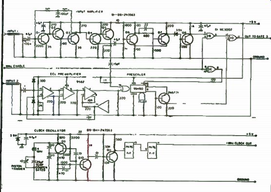
Fig. 10-25. Details: Input Amplifier, Prescaler, Clock Oscillator.
... routed to register A via gates 3A and 3C. FF20A was also set to toggle "on" by FF 21A and the first 1 MHz pulse at the count input of FF 20A causes it to turn on, and gates 5A and 5C cause the display-start line to go high. This readies the display entry logic. ( 1 MHz pulses are routed to register "B," but are not used in this mode.) After exactly one second, FF 21A switches off, and conditions FF 21B to switch off. The next input pulse causes FF 21B to switch off, and gate 3A closes. Register "A" now contains the count of input pulses during a one second interval. FF 20A promptly switches off (about one microsecond later), the display-start line is brought low, and the digit entry logic is initiated. When all digits have been entered (about one-fourth second), the 10/0 line goes low, and the one-shot generates a 1 ms reset pusse, which clears registers "A" and "B" and simultaneously sets decade divider 8 to a count of 9, through gate 4D. About one-tenth of a second later (in the continuous count mode), divider 8 reaches a full count, transmits a pulse to FF 21A, and a new count cycle begins.
Single Count. When line D is high, after the count/display sequence, gates 4C and 4D are locked up by the reset pulse, and divider 8 is held at a count of 9. The start (SCE) line is brought down each time the single count push-button is operated, restarting divider 8, a new count, and resetting gates 4C and 4D. Calculate Frequency (Hz) Mode. A logical 1 on the Hz line enables gate 10D, prevents FF2 1A from resetting from its count input and prevents (gate 10C) the 10/0 line from initiating a reset pulse. Gate 3A is enabled via FF 21A and FF 21B, similar to the kHz mode. It should be noted that FF 20A (which follows gate 3A by one microsecond) routes one microsecond pulses via gate 7A to register "B" in all count modes. In the Hz mode, when register "B" has counted 800 milliseconds, it sends a pulse via gate 10D to reset FF 21A. The next input pulse closes gate 3A via FF 21B, and gate 7A closes about one microsecond later. Register "A" now contains the number of input pulses which were counted during the time (in microseconds) stored in register "B." The display-start line causes entry of the number stored in register "A" a "divide" function, the period measurement in register " B" and a second divide (equals) function (which calculates the frequency), and initiates a reset pulse via the 16/0 line.
Elapsed Time and Event Counting Modes. When the elapsed time line is high, divider 8 is disabled via gate 5D, and either input pulses or timing pulses are routed to register "A," depending upon the status of " D" (gates 9B, 9C and 10B). Microsecond or millisecond timing pulses may be selected by a back panel switch. In the elapsed time mode ("D" is low), the gate may be operated via the regular counter input, or via the manual or external gate inputs. Pressing "Single Count" and " Elapsed Time" together selects event counting, and input pulses are routed to register "A" when the gate is opened manually or externally. In these modes, display-start occurs once each second (gates 5D & 5B), and the reset generator is disabled via gates 1A, 4A and 4B. A single reset pulse is generated each time this mode is selected, which permits each count to start from zero.
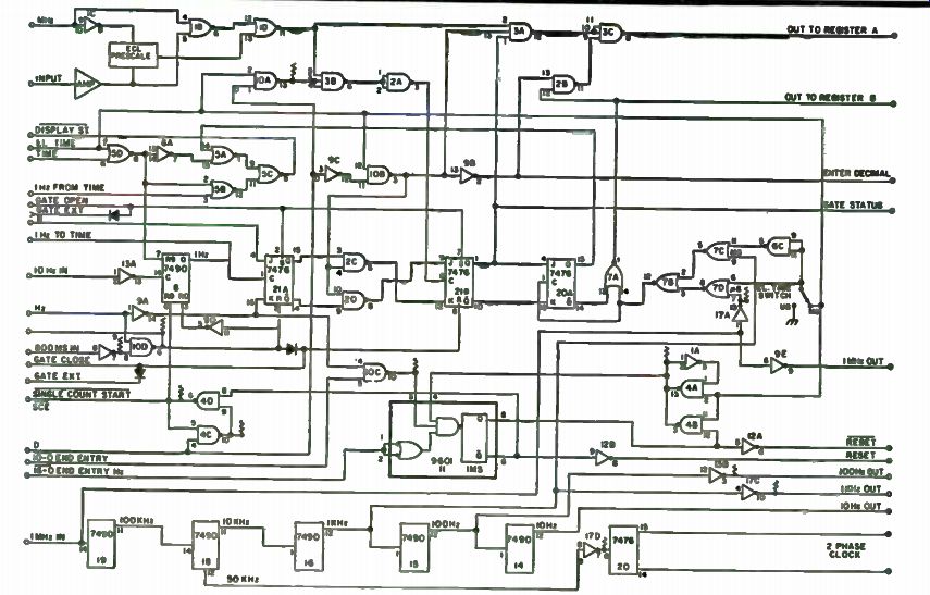
Fig. 10-26. Input Gate, Clock and Reset.
Clock and Countdown Chain. In order to assure count accuracy, the dock oscillator must have high stability. The circuit chosen has proven to be very stable. There is little sense in providing 7 or 8 digits or readout unless the clock oscillator is stable to 107 or 108 or better. When the digital clock is adjusted to keep time to one-half second in 10 days, accuracy is better than 106 . All devices in the clock chain, and the time-of-day register are provided with battery standby. Interfacing between these devices and other logic devices was made via open collector buffers. Provision of pullup resistors to the regular 5 volt line, and powering these buffers from the battery, avoids the possibility of glitches when the counter circuits are switched off.
Registers. Data registers and associated logic are diagrammed in Figs. 10-27 and 10-28. Referring first to Register "A," it can be seen that pulses presented to the input are counted during the interval the input gate is open.
When the gate closes, counting stops and Data Entry Logic is enabled.
Divider 30 (Fig. 5) is caused to count up, at a 20 millisecond rate, from "zero" though 8, and then resets to "zero." Decoder 29 changes the BCD output of divider 30 to a "one of 10" output. Each group of four gates to the data bus is enabled in turn, which causes the BCD output of the associated decade counter (high order first) to be presented to the BCD data bus (gate 24 presents divider 16, gate 23 presents divider 15, etc.). When divider 30 reaches the count of 8, a signal on the "stop entry" line stops further counting of divider 30, resets it to "zero," and in turn prevents further data entry.
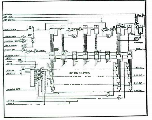
Fig. 10-27. Register "A" and Digital Clock.
At this stage, the calculator is displaying the contents of register "A." In the kHz and MHz modes, no further data entry occurs, and a new count cycle begins.
The time-of-day register utilizes decade and divide-by- 12 dividers to determine the current time. Gates 26A, 27A, 27B, 27C and divider 25 are provided to permit setting the clock. Dividers 1 and 2 divide the 1 Hz pulses by 60, providing one minute output pulses, and storing the "seconds" of the time. Dividers 5 and 6 similarly divide by 60 providing "minutes", and an hourly output pulse. Divider 7 and the divide by 2 (flip-flop) portion of divider 6 provides a 12 hour count register. When a count of " 13" is sensed by gate 8C, the hour register is preset to 1 through the action of FF2 and gates 8B and 8C. The 8280 dividers used in register "A" have a very valuable feature.
When the strobe input is raised to logic"1," the divider is preset to the value found on its BCD inputs.
Time-of-day can then be entered into display, just as if it were a "count." Note that the digits between the "seconds" and minutes, and between the "minutes" and "hours," are blanked in the display, so a dummy entry must be made in these two positions of register "A." Data Entry. Register " B" ( Fig. 10-28) does not require parallel entry, so 7490s were used here (more readily available and cheaper). In the "Hz" modes, divider 18 is caused to count from "zero" up through "15" to zero. Two 7442 decoders provide a one-of- 16 output from the BCD output of divider 18. Table 10-2 shows the data entry "program" for the various modes. Flip-flops 15, 16 and 17, along with associated gates, provide for entry control of both registers, and flip-flops 15A and 15B enter a "decimal" point in the appropriate place during register "A" entry.
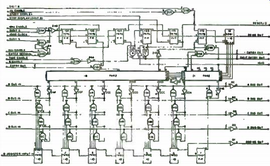
Fig. 10-28. Register " B" and Entry Logic.
Flip-flop 16A is normally enabled, and provides 20 millisecond pulses to the two data entry sequencers. Gate 25A signals the bus converter that there is valid data on the bus, and the converter in turn presents this data to the calculator for 10 milliseconds. The action of flip-flop 16A is inhibited (and no digits are therefore entered) during decimal point entry. Although the 5001 data sheet states 4 ms is required for data entry, anything faster than the 20 ms data entry cycle rate chosen was found to be unreliable with the bargain price 5001. Flip-flop 16B switches "on" in response to a pulse on the start-display line (input gate closure). Flip-flop 17A is then permitted to toggle "on," which unlocks the register "A" data entry sequencer and the "digit entry" line (gate 25C). Register "A" entry sequencer then counts up (entering dies), and when it reaches a count of "8" the stop-display line permits flip-flop 17A to toggle off, which resets the entry sequencer to "zero" and stops further entry of register "A." In the "Hz" mode, a count of "8" on the register "A" entry sequencer permits flip-flop 17B to toggle "on" which enables the 8281 register "B" entry sequencer ( 18) and unlocks the digit entry line at gate 25C. Register "B" entry sequencer then counts up, entering register "B," and at count 15 gate 24D enables the flip-flop 17B "K" input. The next count pulse causes sequencer 18 to return to a "zero" count, and simultaneously toggles flip-flop 17B "off," which disables divider 18.
Input Amplifier and Prescaler. Details of the input amplifier and pre scaler are shown in Fig. 10-25. The input amplifier uses low-cost high speed 2N3563 transistors throughout. The input amplifier has a passband from 1/2 Hz through at least 150 MHz. Some resistor changes were found necessary to optimize response. The 9582 ECL preamplifier was found to have less sensitivity than the discrete preamp, and stability proved a problem. In retrospect, we would eliminate the ECL preamp and use the discrete preamp for all input signals.
Clock Oscillator. Time base stability is very important if accurate counts are to be expected. The oscillator circuit was chosen after much experimentation. The crystal is a 4 MHz HA type (high accuracy) ordered for room temperature use. This frequency seems to be about optimum for thermal stability, and use of a series/parallel combination of NPO and negative temperature capacitors for the crystal series capacitor permits stability to be adjusted. The 10 pF capacitor is a glass piston trimmer can be anything smaller than 10 pF (4 pF probably is about right if you can find one). Q9, Q10 and Q11 are 2N3563 or 2N4274. Use of this oscillator permits stability to one part in 10 period. Only a very slight difference in time keeping ability was noted when the unit was run "warm" for a similar period.
Mode Switching. Use of 8 open collector TTL 2 input NAND gates (or inverters) connected as 4 SR flip-flops permits a completely electronic mode switching system. The configuration of these flip-flops is set by pressing one of the mode push-buttons. The flip-flops then "remember" what mode switch was last pushed.
Outputs at the first three flip-flops are decoded by six 3-input NAND gates. The fourth flip-flop is used to control the single count function, and also, together with the "elapsed time" mode, to provide an "accumulate" mode. LEDs indicate the mode presently in use. Operation of either the kHz or MHz button presets the calculator to 3 decimal places. This permits display of the decimal in the appropriate location. An extra decimal point LED was mounted between the fifth and sixth digits (from the right) and connected via a driver to the MHz function. This provides a reading of XX. XXX. xx in this mode. (Although it might appear that the MHz function should preset 2 decimal places, the decimal point is entered in the proper place by the data entry logic.) Germanium diodes should be used in the "decimal preset" line to ensure that TTL inputs are brought below their switching thresholds.
Power Supply. In order to avoid loss of power to the digital clock, a battery standby has been provided for the clock circuits. Referring to Fig. 10-29, a constant current regulator, comprised of a 2N3055 and a 2N3569, maintains the Nicad battery in a fully charged state. The voltage regulator using another 2N3055 and a 2N3698 is somewhat unusual. A voltage doubler driven by G1 and G2 provides sufficient current to the 2N3055 to maintain it in saturation when the input voltage drops to 5.2 volts or less. This ensures adequate output voltage to drive the TTL clock circuits until the battery voltage drops to about 4.7 volts. At this point, zener diode Z1 (with diodes D5 and D6) reduces the base current to the 2N3055, which results in a drop in output voltage. Lowered voltage to the TTL countdown chain causes a loss of clock drive to the voltage doubler, and results in a complete shut down of the voltage regulator. Deep discharge of a Nicad battery would result in permanent cell damage.
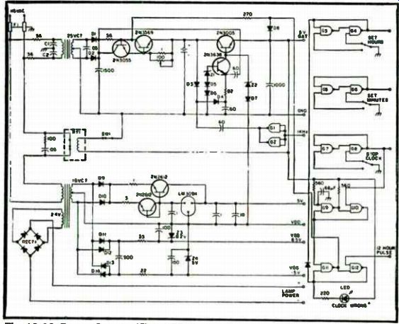
Fig. 10-29. Power Supply. This LED signals a power off condition until the
clock is reset.
Zener diodes Z1 and Z2 with their associated forward diodes must be chosen to provide about 5.7 volts at the base 9f the N3055, and about 5 volts at the base of the 2N3638.
The main 5 volt supply uses a PNP 2N2612 transistor to provide about 4 amperes of regulated DC, controlled by the 1 Ampere LM309K. The second 2N2612 is diode connected to provide a voltage drop similar to the base-emitter drop of the pass transistor, and as it is mounted on a common heat sink provides thermal stabilization. MOS voltage levels are provided by simple zener regulators. Note that Vdd is grounded, wheras the 5001 data sheet references voltage levels to Vss. Lamp power is unfiltered, which reduces readout brilliance changes with the widely varying readout load.
Three bounceless switches are provided for setting the time. Gates G9, G10, Gil and G12 increase the battery charge rate upon restoration of power after discharge. The high rate continues until first the "stop clock" (set seconds) switch is operated, and then a 12 hour pulse is received at midnight or noon. (That is, the high rate stops at noon or midnight after the time has been reset.) Using the Calculating Counter. The completed counter has proven to be a very useful tool. By merely switching the unit on, the precise time is immediately displayed. Instead of those laborious parallel resistor computations with pad and paper, a precise calculation can be quickly made on the calculator. A short piece of wire attached to the input and placed near an antenna allows checking of transmitter frequencies. (A hand held business portable yielded a reading of 155.610.15 MHz-authorized frequency 155.610.) As indicated earlier, while we wished to be able to measure frequencies through 2 meters, low audio frequency resolution was a prime target. All frequencies above 10 Hz may be measured to 5 or more significant figures.
An Inexpensive Modularized 50 MHz Counter
Need a relatively simple but effective counter? If it has to be easy to build and it has to be able to count to 50 MHz without using a prescaler you'll love this project. After giving the design approach considerable thought, we decided on the plug-in board method. Then we proceeded to break up the total circuit into the individual circuits that make up a frequency counter and design PC boards for each of them. Counter circuits are pretty basic and there are only so many ways to design one, so this one may look a lot like others. There are, however, a few new ideas.
One of the worst features of any counter is the awful current drain that the LEDs in the display manage to consume. Even with current-limiting resistors, 8 digits at 20 mils per segment can pull 1.12 amps. We got around this by scanning the display so that only one LED is on at a time. This reduces current consumption by one eighth. We also decided to get rid of that ridiculous number of resistors, since scanning the LEDs gave us a 10 percent duty cycle. This meant that the average current through the LEDs would be 10 percent of the maximum current without resistors. Checking the specs for the LEDs we were using (MANS) showed that at 5 volts the...
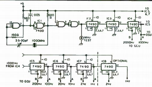
Fig. 10-30. Timebase Oscillator and Divider.
...maximum current per segment would be 192 mils. But 10 percent of that is 19.2 mils and is within the maximum of 40 for the LED. The maximum current drain is now reduced to 134.4 mils when the display is showing an 8.
Another change we made is the use of a 74LS90 as the first counter in the chain. The 74LS90 is pin replaceable for the 7490 and will count in excess of 50 MHz. Some designs use the 74196, which uses inverted logic as compared to the 7490. The 74LS90 uses the same logic so board design is simplified.
We also added the option of selectable gates, 0.01 sec, 0.1 sec, 1 sec and 10 sec.
Breaking the counter down into individual boards, there is the Time Base Oscillator and Divider (TBOD), Display Scan Unit (DSU), Decimal Counter Unit (DCU), Gate Control Unit GCU) and Preamp. All these units...
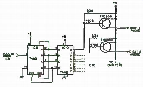
Fig. 10-31. Display Scan Unit.
...plug into a master board which has all the interconnecting circuit paths etched into it.
Approximate cost, less cabinet, is about $85 using all new parts, less if you have a well-stocked junk box and can make the boards yourself. Figures 10-30 through 10-48 illustrate this entire project.
Timebase Oscillator and Divider. The TBOD is constructed on a PC board that is 3.5" by 2". Due to the compactness of the circuit it was necessary to use jumpers for the frequency outputs. A double- sided board could be made and eliminate that need, but in the effort for simplicity we decided against it. The TBOD consists of a 7400 NAND gate for the oscillator and a series of 7490s wired to divide by 10 in the bi-quinary mode.
This method gives a symmetrical square wave at the output, needed for proper gate timing. Also, the divide by 5 signal is brought to the edge of the board, as these frequencies are also needed. 1000 Hz is also used by the Display Scan Unit, so it has two outputs.
Curious as to the stability of this circuit since the crystal only has a tolerance of . 005 percent, we checked it against a 1 MHz signal with a known accuracy of 1 x 10.
Provision has also been made for bringing the 1 MHz signal out to the back panel of the counter for checking it against another signal.
This is also the most expensive of the units, costing about $15 with all new parts.
Display Scan Unit
The DSU is also built on a 3.5" by 2" PC board. The DSU has a 7492 divide by 12 counter wired to reset to 0 at the count of 10.
The BCD outputs of the 7492 are connected to the BCD inputs of a 7442 decimal decoder, which is used to scan the display LEDs by switching the Vcc on and off through a PNP switching transistor. The emitters of the transistors are connected to positive 5 volts and the collectors are routed to the anodes of the LED display. Pull-up resistors are used to keep the transistors biased off, along with current limiting resistors on the bases. If 5 volts does not provide enough brilliance from the LEDs, a slight modification on the board will enable you to use more than 10 volts, however. More than that and the LEDs may burn out.
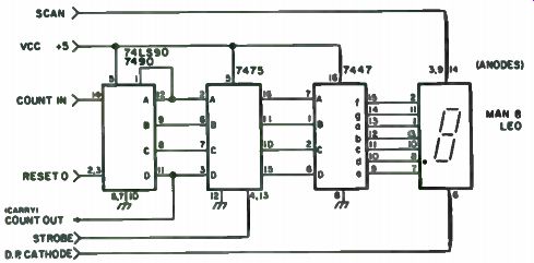
Fig. 10-32. Decimal Counter Unit.
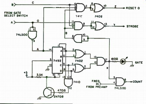
Fig. 10-33. Gate Control Unit.
The outputs of the 7442 are active low. That is, the output selected is at ground and all others are high. Grounding the base of a PNP transistor turns it on and switches Vcc to the proper LED. Because the 7492 is wired to divide by 10, the scan rate figures out to 100 Hz. This is fast enough to eliminate any flickering, but allows enough brilliance for normal room fighting.
With all new parts, the DSU costs about $6.25.
Decimal Counter Unit. The DCU is constructed on a 3.5" by 1.7" PC board. Except for the first DCU, all use standard 7490s as counters. The first DCU uses the 74LS90 by Fairchild, which was described earlier, for a 50 MHz count rate. Also, each DCU has a 7475 quadruple bistable latch, a 7446 or 7447 BCD to seven-segment decoder, and a socket for the LED. Any Monsanto LED may be used here as the pin-outs for most of them are identical. We used the MAN8, which is yellow, simply because we had them.
However, the large . 6" MAN6 or the . 27" MAN7 will also plug in. Both of these are red.
For the LED socket, use the already preformed side mount socket or be cheap and bend the leads of a wire-wrap socket.
The 7475 is used to transfer the accumulated count of the 7490s to the display when strobed by the Gate Control Unit. A logic one is needed on the clock inputs to transfer the input information. When the clock is low, the latch will store the information until the next strobe pulse. li the input has not changed, the output won't either. If new information is present at the input, the outputs will change to agree with the inputs.
The outputs of the 7475 are connected to the inputs of the 7447 which decodes the BCD to the proper coding to display the corresponding decimal number on a seven-segment readout.
Four of the DCUs have provision for using the decimal point so that the display can be wired to show the frequency in either kHz or MHz. One need only wire the proper decimal point to ground through the gate select switch.
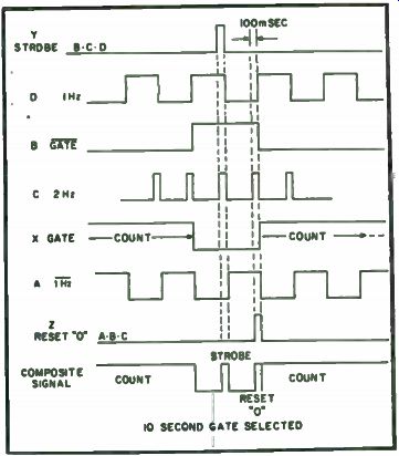
Fig. 10-34. Gate Control Timing.
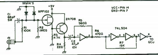
Fig. 10-35. The Preamp.
The cost of the DCU will be about $6.50 for the 50 MHz version, and a little less than $6 for the standard version.
Gate Control Unit. The original circuit for this was unsatisfactory, as the time needed for the strobe and reset 0 pulses was equal to the gate time. On the faster gates this was no problem, but on a 10 second gate it could be annoying having to wait 20 seconds for updating the display. So we rede signed it with the basic idea that we wanted a 10 second gate and the resets to occur within one second. A look at the timing diagram may help in understanding the operation of this circuit. Refer to the schematic for lettered lines. Note also that the board has a gate LED incorporated on it, eliminating the need to front panel mount one. It will show through the display window to the right of the digits.
The GCU is built on a 3.5" by 1.7" PC board. It consists of four ICs: a 7492, divide by 12; a 7410, triple-three input NAND gate; a 7402, quadruple two-input NOR gate; and a 74LS00, chosen also for the high toggle speed.
Let us assume we have selected a 10 second gate. Through the gate select switch, 1 Hz and 2 Hz signals are routed to the inputs of the GCU. One gate of the 74LS00 is used to invert the 1 Hz and apply it to the clock input of ...
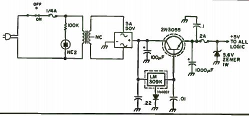
Fig. 10-36. Power Supply.
... the 7492. Normally this IC would count to 12 and reset to 0, but with the 7410 gate connected to the A, C and D outputs, it will be forced to reset at the count of 11. Zero detecting the outputs with a NOR gate and NAND gate will produce a pulse that is high for 10 seconds and low for one second, which is the time between reset and the next input cycle. Another gate of the 74LS00 is used to invert this pulse.
By combining the inverted gate pulse with the 1 Hz and 2 Hz signals, and then inverting the outputs of the other two gates of the 7410, the Strobe and Reset 0 pulses are generated and transferred to the rest of the counter.
Through trial and error it was found that there had to be a minimum amount of time between the two pulses and this circuit provides it. Unfortunately, due to the minimum pulse width needed to reset the 7490s in the counter (50 nsec), the fastest gate time allowable is . 001 second. This is probably faster than needed anyway.
The current limiting resistor for the LED should be chosen for the particular LED being used. Generally, about 180 ohms should be right. Any color may be used.
Fig. 10-37. 50 Mhz Frequency Counter.
This is also the cheapest unit, costing about $4.00 with all new parts.
The Preamp. We used a 74LSO4 to obtain a 50 MHz working speed, a 2N708 for Q2 and a slightly different input scheme, in addition to the k20AW counter. Finally, sensitivity became livable. A scope and rf signal generator (HP 608D) showed a sensitivity of 10 mV from 10 MHz on up. At audio frequencies, about 50 mV was needed for reliable operation.
The reason for all that extra space on the board layout is that in the future, an onboard prescaler using the 11C90 by Fairchild will be incorporated. Provided, of course, that the circuitry is as simple as that using a 95H90. With the 11C90, the counter should operate in excess of 500 MHz.
Power Supply. Due to heavy current demand, about 1.3 amps, we decided on the circuit shown to regulate the 5 volt line, rather than use two LM309s. All components can be mounted on the rear panel with appropriate mounting hardware and solder lugs. Heatsink the pass transistor and LM309K. You can use a bridge rectifier module or individual diodes. They should be rated for at least 5 amps at 50 volts. The transformer is a 12. 6v AC at 3 amps, or parallel two smaller rated ones. Use a 2N3055 for the pass transistor or a suitable substitute with similar ratings.
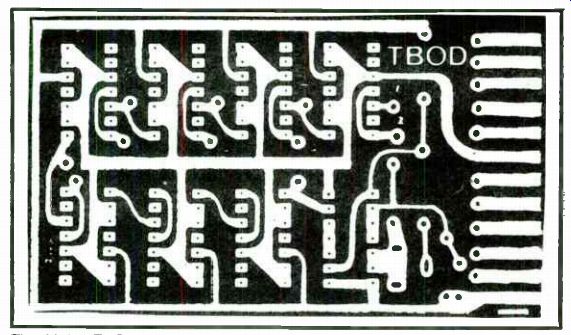
Fig. 10-38. TBOD board (full size). The fuses should be of the fast blow type.
Fuse holders mounted on the rear panel provided the best method, but they can
be soldered in inside the chassis. The power switch can be eliminated so that
the counter is on whenever the line cord is plugged in.
General Construction and Testing. After etching and drilling all the boards, install the jumpers first because two on the GCU are under ICs.
Next put in the resistors and capacitors, and then the transistors and ICs.
The LED sockets on the DCUs come next; then install the LEDs. Install the sockets on the master board.
Wire the power supply in the case, along with the front and rear connectors and switches. Secure the master board to the case with small angle brackets, at least 4" behind the front panel. This will allow the boards to be installed and removed easily. Or the master board may be hinged at the bottom to tilt back. Next do the main wiring from the power supply to the ...
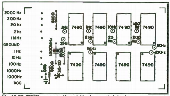
Fig. 10-39. TBOD component layout. Use jumpers to bring frequency outputs
to edge. 1 board per counter. Dot indicates pin 1.
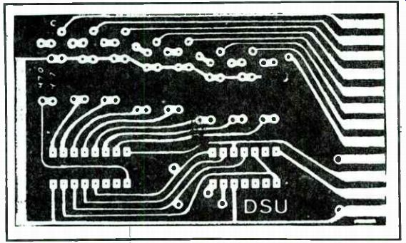
Fig. 10-40. DSU board (full size).
...master board and the front panel switches. Use RG-174 for the counter input and the 1 MHz test output. Location of the controls and cutouts is entirely up to the builder and depends on the case used.
Before installing any boards, check the power supply for proper operation. If it's working, turn the power off and install the TBOD in the 12 contact socket on the left (from the front of the counter). An accurate frequency counter will be needed to set the 1 MHz oscillator, at least 1 x 10'8. Turn the power on and with the counter connected to the 1 MHz test output, adjust the trimmer to read 1 MHz, plus or minus a few Hertz. If it won't adjust, try another 7400. This is an initial adjustment. After the rest of the boards are installed, and at least a one hour warm-up period, recheck the frequency. Before turning off the power, check the divider chain for proper frequency outputs. If everything checks out, turn the power off and install the GCU board. Select the one second gate and turn the power on. If the ...
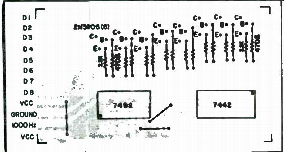
Fig. 10-41. DSU component layout. 1 board per counter. Dot indicates pin 1.
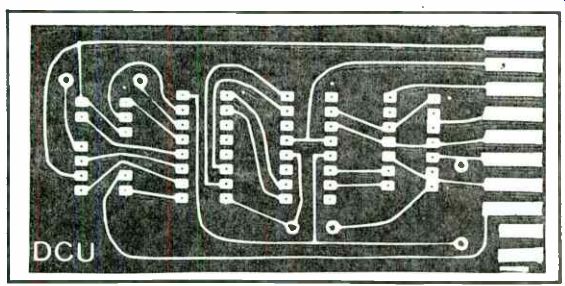
Fig.10-42. DCU board (full size). GCU is working, the gate LED will blink
on for one second and off for 10 msec. Check the Reset 0 and Strobe outputs
with a scope for a 10 msec pulse. If the GCU checks out, turn the power off
and install the DSU board.
Turn the power on and check each of the DSU outputs with a scope for proper switching. A frequency of 125 Hz should be measured. If the DSU is working, turn off the power and install the DCUs. Turn on the power and check that the display reads all Os. If not, make sure all the boards are in the sockets tight or check for unsoldered connections, or bad ICs. If all Os are displayed, turn off the power.
Install the Preamp board and turn the power on. The display should still read all Os. If not, the DSU may need bypass capacitors on the Vcc line on the master board. Any signal on the Vcc line greater than about 20mV will trigger the Preamp and cause false counting with no input. Any input signal will have to exceed this by at least 10 mV to be counted.
If you get all Os on the display, proceed to check out the whole counter by using a signal generator to check the frequency response and sensitivity.
You may want to keep a graph or record of the results for future reference.
Fig. 10-43. DCU component layout. Use side mount socket for LED ( see text). One DCU uses 74LS90 for 50 HMz count speed. 6 or 8 boards per counter. Dot indicates pin 1.
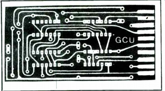
Fig. 10-44. GCU board (full size).
All that's left to do is recheck the TBOD frequency and button up.
Troubleshooting. If you run into difficulty getting the oscillator to zero on exactly 1.000 MHz, try another 7400. Some will oscillate better than others. It has something to do with the characteristics of different batches.
You can use a scope or another counter to check the divider chain for proper division. On the GCU, a dual-trace scope is nice because you can check and compare the waveforms at more than one point and reference them to another. Most problems here are caused by loose ICs in the socket.
Actually, most problems can be cured simply by trying a different IC. If you still run into difficulty, look for solder bridges, bad connections, wiring errors, or even the possibility of a leaky or bad transistor.
One can save in construction costs by not using sockets for the ICs, although it's a good idea to make certain the IC is good first. It's not fun unsoldering them. Do use sockets for the LEDs, though. The preformed ...
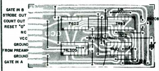
Fig. 10-45. GCU component layout. Use sleeving to insulate resistor lead.
1 board per counter. Dot indicates pin 1.

Fig. 10-46. Preamp board (full size). side mount ones are best, but a wire-wrap
socket will do just as well if you carefully bend the leads with needlenose
pliers.
Try for a trade-off between price and visibility on the display. Sure, those large 6" LEDs are easy to read, but expensive. The cheaper, . 27" ones will work just as well, and they can be had in different colors: red, green, yellow or even orange.
The Amphenol PC card sockets are available from Cramer International, Newton, Mass., or the local office in your area.
The cabinet will have to be at least 3 1/2" high, 10 1/2" long, and 7" deep.
Make sure you leave at least 1/2 " between the LEDs and the back of the front panel for removal of the plug-in cards.
If you don't need more than one gate, eliminate the switch and hardware the circuit. The switch used here is shorting miniature rotary, Centralab #PS- 11. The extra position and pole made it possible to turn the power on when selecting the timebase. For a complete parts list, see Table 10-4.
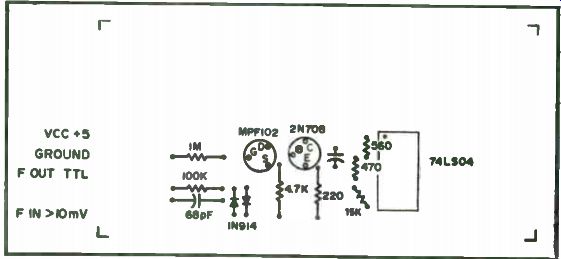
Fig. 10-47. Preamp component layout. Resistors are 1/4 Watt. R5, R6, R7 are
mounted vertically. 1 board per counter. Dot indicates pin 1.
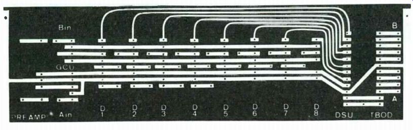
Fig. 10-48
---------------------

Table 10-4. Parts List for Frequency Counter.
TBOD 1 7400 7 7490 1 PC Edge Connector Amphenol #143-012-03 8 14 Pin DIP Sockets 2 680 Ohm 1/4 Watt 1 150 Onm 1/4 Watt 1 3.5-20 pF Variable E.F. Johnson #274-0020-005 1 .005 uF Disc 1 1.000000 MHz Crystal 1 PC Board DCU 1 74LS90 (50 MHz Version)
7 7490 8 7475 8 7446 or 7447 8 PC Edge Connectors Amphenol #143-010-03 8 Seven -Segment LEDs (See Text)
8 14 Pin DIP Sockets 8 14 Pin Wire Wrap Sockets 16
16 Pin DIP Sockets 8 PC Boards Power Supply 1 12.6 V ac, 3 Amp Transformer 1 1 50V, 5 AMP Bridge Rect.
1 2N3055 1 LM309K 1 100µF, 25 V 1 1000p,F, 10 V 1 .01 e LF Disc 1 1 8 8 8
0.1 uF Disc
.22 Disc 1N 4001 DSU 7492 7442 PC Edge Connector Amphenol # 143-012-03 14 Pin DIP Socket 16 Pin DIP Socket 470 Ohm 1/4 Watt 2.2k 1/4 Watt 2N 3906 PNP Transistors PC Board GCU 74LS00 7402 7410 7492 PC Edge Connector Amphenol # 143-010-03 4 14 Pin DIP Sockets 1 470 Ohm 1/4 Watt 1 3.3k 1/4 Watt 1 2N708 NPN Transistor 1 LED 1 @ 180 Ohm 1/4 Watt PC Board Miscellaneous Gate select switch BNC connectors, plastic window, use holders, hardware, knobs, cabinet, etc.
------------------------------ 300 MHz Frequency Scaler
This project is about building an IC frequency counter good up through the VHF range. That design has a built-in frequency scaler, and is good through almost 300 MHz. For those who have a low-frequency counter and just need a scaler to extend the range, here is a simple design which can be built for about $20. The heart of the unit is a Fairchild µ6B95H9059X divide-by- 10 scaler IC, which costs about $16 in unit quantities; we call it a 95H90 for short, and it's ICI in Fig. 10-49, the schematic diagram. The output of this IC is fed into a 2N5771 PNP transistor which amplifies the output and provides a voltage change. If you have a counter which will go up to about 15 MHz, then this part alone will extend your range to 150 MHz. But if you have a slower
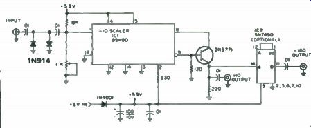
Fig. 10-49. VHF scaler schematic diagram. All 0.01 capacitors are disks.
All resistors are 1/4W, 10%. counter, then you will need IC2 as well. This
is an inexpensive ($1.30 or so) SN7490N TTL decade counter, which does a second
division by 10. Both IC's together will take a 150 MHz signal and divide it
down to 1.5 MHz.
The IC's need a voltage between +5 and about +5.3 volts. While you could build a power supply, that only increases the cost. The easiest way to provide power is with four D cells or a 6-volt lantern battery, which provides + 6 volts. The 1N4001 diode, or another silicon power diode, drops this to about +5.3 volts. The scaler needs about 150 mA, so a set of four D cells will last about 10 or 20 hours with intermittent use.
Figure 10-50 shows a printed circuit board layout which can be used to mount the scaler, and Fig. 10-51 shows the parts placement on the board.
Leave the copper border around the board, to act as the ground connection for the board. Use phono jacks or rf connectors, and bypass the +6 volt lead.
The purpose is to let rf into the box only via the input lead.
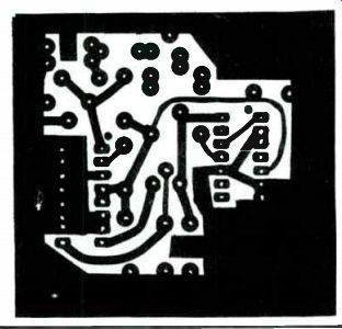
Fig. 10-50. Copper side of PC board, actual size.
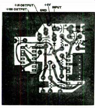
Fig. 10-51. Parts layout diagram (component side). In use, avoid over-driving
the scaler. Start with a low input level, and feed in just enough rf to get
a counter reading. With a 19- length of wire connected to the input lead you
should be able to activate the scaler with a 1 or 2 watt hand-held unit from
a few feet away.
Increased Speed for the k20AW Frequency Counter This project involves the construction of a frequency counter with a low frequency (0-20 MHz) input and a divide-by- 10 prescaler capable of extending the upper frequency knit to 300 MHz. The counter is built using mostly surplus ICs and junk box parts and it works the first time you plug it in. By sorting the ICs according to speed, we were able to obtain a stable upper frequency limit of 32 MHz in the low frequency position. Much experimentation was accomplished on the front end of the counter, including the 40673, the 7413 and the 7400 input selector. Maximum attainable speed remained in the 32 to 34 MHz range.
The main problem appeared to stem from the limited speed of the 7473 flip-flop which comprises the divide-by-two function of the first decade.
Simultaneously with the discovery of the apparent problem with the 7473, low cost Schotty TTL ICs became available from some of the surplus companies. (They are available from Solid State Systems, P.O. Box 773, Columbia, MO 65201.) A 74S73 flip-flop was obtained and plugged into the IC5 position on the circuit board and things started to happen. Using a four turn wire loop on the counter input and a grip dip oscillator as a signal source, the counter's upper limit was found to be 62MHz! Subsequent checks proved that the initial test was not a fluke and the counter was now stable from 20 to better than 60 MHz.
IC Audio Frequency Meter
The 555 integrated circuit can easily be made into an inexpensive linear frequency meter covering the audio spectrum. The 555 is used in a monostable multivibrator circuit. The monostable puts out a fixed time-width pulse, which is triggered by the unknown input frequency.
Referring to Fig. 10-52, transistors Q1 and Q2 are used as an input Schmitt trigger. The unknown frequency input is clipped between 9 volts and ground by these transistors. Positive feedback is used to insure the waveforms have fast, clean edges. The output of Q2 is a square pulse with the same frequency as the input signal. The output of Q2 is differentiated by C2 and R2 to provide a short pulse for the 555. A small signal diode is connected across the differentiator to insure that the 555 input never exceeds 9 volts. The 555 is connected in the standard monostable circuit.
Since a Schmitt is used to trigger the monostable, square, sine and ramp type waveforms may be used at the input to the frequency meter. A nominal voltage of 1 volt rms is required to trigger the Schmitt circuit.
The range scale timing resistors R3, which determine the monostable pulse-width, are small potentiometers mounted directly on the circuit board.
These pots are used to calibrate each frequency scale.
The output of the monostable is a fixed width pulse. Every time a zero crossing of the unknown frequency occurs, the monostable is triggered.
Thus, as the frequency of the trigger pulse increases, the monostable output has a greater and greater duty cycle. The frequency limit on any one range is determined by the R3C3 time constant re-triggering, and a constant 9 volts will appear at the output.
The monostable output is a pulse with a duty cycle dependent upon the input frequency. Thus, by integrating or averaging the output waveform, a DC voltage is developed. This voltage is directly related to frequency.
Resistor and capacitor R4C4 is used as a pulse averager, important on the...
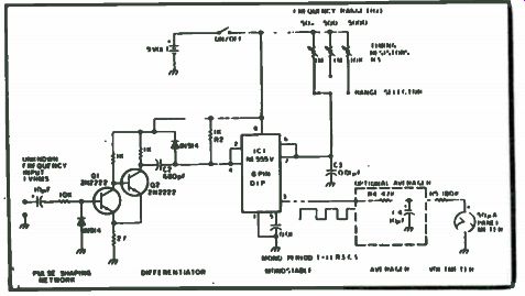
Fig. 10-52. 555 timer frequency meter.
...can act as a waveform averager. Input frequencies greater than 50 Hz will be averaged by the meter fairly well; however, at lower frequencies the meter will respond to each cycle of the unknown frequency input. The meter is used as a high impedance voltmeter. A 1 mA meter could be substituted with a change of resistor R5. For a 1 mA meter, R5 should be about 9.1k and R4C4 should be changed appropriately. R4 should be a factor of 10 less than R5, and the same R4C4 time constant should be kept. This would make C4 a very large value, so R4C4 could be left out if the lower frequencies are of little interest (less than 50 Hz). The range scales are set up in decades. To calibrate each scale, a standard input frequency is connected to the input. About 1 volt rms is needed to trigger the first stage. The monostable must be less than the maximum input frequency to be measured on each scale. With the maximum input frequency applied, each range potentiometer should be adjusted until the value of the input frequency corresponds to the full scale meter reading.
The duty cycle of the monostable should be roughly 90 percent at the maximum frequency input for each scale setting. If, for a 90 percent duty cycle, the meter will not read full scale, meter resistor R5 should be lowered accordingly. Each scale setting should be calibrated by adjusting the respective R3 potentiometer.
During operation, when the scale reads off scale on any range, the scale should be changed to the next higher setting. Once calibrated, this frequency meter should read within 5 percent of full scale. The useful frequency range of the meter is from tens of Hertz to well over 50 kHz.
Although decade ranges are shown, the ranges between the decades can easily be added to give as many frequency ranges as deemed necessary.
The Speedy Audio Counter
he need for fast and accurate measurement of the low frequency tones in an electronic organ provided the basic drive to produce this counter (Figs. 10-53 through 10-55). An earlier version was slightly less costly, but far too slow and lacked the needed resolution. This design works well, and should find acceptance with those wishing for precise measurements for most audio frequency applications.
Most electronic organs contain a master oscillator board that uses 12 slug-tuned coils for generating the highest tones, or the top octave. These are followed by a divider chain that provides successively lower octaves. It was decided to measure one of the lower octave ranges that spans from C6 ...
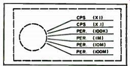
Fig. 10-53. Range
switch scales.
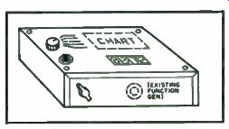
Fig. 10-54. Oblique view showing general outward appearance.
... at 1046.50 Hz to C5 at 523.25 Hz. With a conventional counter, a 10 second gate would provide tenths of Hertz resolution at best, and a longer gate time is out of the question. The only reasonable approach is to count the number of higher frequency pulses that occur during one or more cycles of the frequency being measured. For example, if the number of one microsecond pulses were counted during one cycle of A5 at 880.00 Hz, you would get 1136. A 10 cycle count gives 11363, and 100 cycles will read 113636. The period of one cycle of A5 is . 00113636 seconds, so 100 cycles requires just over . 1 second. You get the required resolution and fast update to the counter. To calculate the required display reading, just divide the reference frequency by the input frequency in Hertz.
A look at Fig. 10-56 shows that CMOS integrated circuits are used throughout. A four stage display counter consisting of 4026s count and decode to seven segments in decade fashion. These were used in preference to 4033s, as they have a display enable input that permits us to blank the display while resetting or counting. No latches are used as it was found a "blinking" display is actually easy to use. A new display means an updated count. 4049s are used with 680 ohm resistors for segment drive to MAN-1 readouts. Three 4518s are used for the timebase divider to provide 100 kHz pulses, or . 1 second and 1 second timebases. A 4518 is also used to divide the input to give xl, x 10 and x 100 ranges. Two sections of a 4001 are used for the crystal oscillator and buffer and two sections of another 4001 comprise the input amplifier. The input amplifier is biased slightly above or below the threshold point to prevent random triggering. A 4013 and three ...
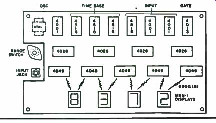
Fig. 10-55. Top view of component board.
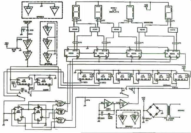
Fig. 10-56. Schematic.
... sections of 4001 are used to provide synchronization and division of the input, reset, display gating and clock pulses to the counter chain. This gating system requires a minimum of parts, yet provides a 50/50 gate and display cycle. The reset is one-half cycle of the reference frequency that immediately proceeds the count. As the 4026s require less than 0.5 usec for reset, it may be possible to use a higher reference frequency.
A two section, six position switch permits switching between the two count modes. Position A gives a direct reading in Hertz per second. Position B gates for 0.1 second. These two scales give a positive reference for gross tuning adjustments or quick identification of an unknown frequency.
Switch position C provides pulses at a 100k rate and D at a 1 microsecond rate. Positions E and F bring in the input divider to give an effective x 10 and x 100 in resolution. An example of expected readings of A5 at 880.00 Hz would be: A-0880, B-0088, C-0113, D-1136, E-1363 and F-3636. The more significant digits drop off on the higher resolution scales, but it was felt that an overflow indication was not needed.
Construction was on a piece of perfboard with holes spaced . 1 inch, mounted under the top cover of an existing function generator. The cabinet measured 7" wide, 5" deep and 3" high. The perfboard was slightly smaller with a section removed to permit the switch and input jack to be mounted on the top. The LEDs, ICs and resistors were mounted on the top of the board, and point-to point wiring used for connecting the components. The power supply is mounted on one end of the box. The crystal, originally from a BC-221 frequency meter, was removed from the metal cover and mounted on the board. If you have enough room in your cabinet, it would be better to leave it as is, and mount it with a clip or octal socket. A slot was cut out to reveal the LEDs and covered with plastic laminate for protection. A switch position scale and a chart of frequencies and their respective periods were typed up and pasted to the top, covered with more of the plastic laminate.
How Accurate Is Your Counter?
There is much misunderstanding among the ranks as to counter frequency accuracy, how a counter should be calibrated and the relationship with one's transmitter output frequency. This project's intention is to shed light upon the multiple ramifications involved in frequency counter calibration.
A most likely starting point, therefore, is the counter time base oscillator. This usually is comprised of a 100 kHz, 1.0 MHz, 5.0 MHz or 10.0 MHz crystal oscillator which may or may not be temperature stabilized with an oven. Typical time base accuracy may be as good as one part in 10,000,000 (1/10) or less per 24-hour period. If measurements with reasonable repeatable accuracy are expected, the counter will require a minimum warm-up time of one hour with 24 hours' time being recommended. If the counter is being calibrated to factory specifications, a 24-hour period becomes minimum and 3 months is not unheard of.
A laboratory-type crystal reference oscillator used to calibrate the basic time base oscillator in a counter generally does not reach its stabilized aging rate until a minimum "ON time" of 3 months. This type of standard has its complete oscillator circuit encased in a heavily constructed double oven (an oven within an oven). The typical size of such an oven may be as small as 8" long and 3" in diameter and ovens twice this size are quite common. Such oscillators, when calibrated against WWVB or WWVL, 60 kHz and 20 kHz, respectively, have accuracies as great as one part in 100 billion ( 1/1011), with 1/10 transmission from Boulder, Colorado is 1/101°, one part in 10 billion. Because of signal path distortions, however, the accuracy is de graded by about two orders of magnitude or possibly more. This is known as "The Doppler Shift." The received accuracy is now 1/108 or less. Under the most optimum of receiving conditions and using the best calibration techniques, including an overall time period of 6 weeks for the daily corrections of the crystal oscillator frequency, one could achieve a counter time base accuracy of one part in 10 frequencies of 2.5, 5.0, 10.0 or 15.0 MHz because of the limited accuracies available. The low frequency transmissions of WWVB and WWVL are used as they are not subject to the same types of transmission frequency distortions. In addition they can be and are transmitted with much higher accuracies. The transmitter oscillators of WWVB and WWVL do not use crystals. They are controlled by atomic references.
The Cesium Beam standard is an atomic resonant device which provides access to one of Earth's invariant frequencies in accord with the principles of quantum mechanics. It is a true primary reference and requires no other reference for calibration. A cesium atomic beam resonator control led oscillator is used and is the nation's primary frequency reference. The accuracy of transmission is 1/1013, one part in 10 trillion.
The transmissions of WWVB on 60 kHz are intercepted on receiving equipment of very narrow bandwidth, usually a few Hz wide. The time interval between a local reference oscillator and the frequency of WWVB are compared minute by minute on a strip chart recorder which records the phase differences. The resolution of this comparison is typically 1 us. One part in 101° takes 104 sec. to achieve a 1 usec. error (somewhat less than 3 hours). The transmission of WWVB is coded in the binary coded decimal system. The characters are formed by variations of the carrier in ± 10 dB levels. This presents time-of-year information each minute: the minute, hour, day of the year and the millisecond difference between the broadcast signal and UT2 time.
The crystal oscillator, although not the most stable, is still the most economically available to the hobbyist. It is also compact in size and fits easily into the geometry of a compact frequency counter. The frequency counter does have a number of inaccuracies and the crystal reference frequency oscillator is the major one.
The crystal is the time reference base for a divider chain which basically sets up start and stop trigger pulses in the counter. The counter has a number of these, 1Hz, 10 Hz and 1 kHz being typical. Besides the time base inaccuracy there is also an inherent trigger error which causes a ± 1 count in the readout. The crystal when first turned on has a large drift error. 'This is overcome by use of an oven and a warm-up period. Thereafter the crystal has an aging rate. This is a constant periodic upward change in frequency with time. All crystals have it. After about 90 days of ON time this rate becomes quite predictable and can be compensated for if the oscillator is equipped with a dial capable of a 1,000 to 1 or better resolution. On the finer laboratory oscillators this vernier readout can be related to time in microseconds.
The average hobbyist is most apt to set up the counter's reference oscillator by zero beating the counter's time base reference oscillator against WWV's high frequency transmissions. This is generally performed aurally after a warm-up period of 1-5 hours. Most often, the inexperienced hobbyist may wind up by beating against the audio of the transmitted signal in which case the crystal will be set to the wrong frequency. WWV usually uses 440 Hz for a period during the hour, then shifts to 600 Hz. If the oscillator has been zero beat to one of these, the error will become apparent when the modulation frequency is changed as the apparent zero beat will have disappeared.
A comment quite often heard by lab technicians and radio experimenters contains the following substance: " I have the audible capability to zero beat a signal emanating from the speaker of my receiver." If this is so, then these individuals have indeed been endowed with a very special human ability, especially when one considers that the human ear cannot hear frequencies below 30 Hz regardless of their amplitude. This also brings into view the necessary unusual hi-fi characteristics required of the receiver's output transformer which probably does not respond below 100 Hz-to response. What one actually is hearing is a difference in the amplitude in the noise frequencies accompanying the signal.
A recommended procedure that affords quite good zero beat capability and is readily available to most radio experimenters is as follows:
• Tune in the WWV frequency to be used. The reception of the signal should be free of fading.
• The oscillator signal to be calibrated should be coupled so that its amplitude closely equals that of the incoming WWV carrier level.
• Zero beat aurally as closely as possible, then continue refining the adjustment while observing the receiver "S" meter indication. As zero beat is achieved the "S" meter will reach either a maximum or minimum stabilized indication. This reading will be maximum if both signals are of the same phase relationship or minimum if the phase is out by 180 degrees. It is of little concern which is obtained just so the meter needle has stabilized its position.
If the crystal is of high stability quality and is in an oven, one might want further refinement in the long-term stability capability. In such case it will be required that the crystal oscillator be left on continuously. Further refinements in the zero beat setting will be required each 24 hours, first to correct for the initial phase error setting and then to correct for the crystal aging rate. These further refinements could result in parts in 107 accuracy.
For long-term stability a 1.0 MHz or higher crystal is recommended.
Zero beat becomes more difficult the higher the WWV referenced frequency. This follows because the resolution of adjustment is reduced and you are working to a finer tolerance.
Assume that the received signal is accurate to 1 part in a million (± 10) and that the adjustment you have just made was set to zero beat with ± 10-6 of the received signal. This will produce a short-term accuracy of ±2/10 of ±294 Hz depending on which side of the WWV carrier frequency you are zeroed in on. This accuracy will decay with time elapse between the act of calibration and use of the counter.
For those fortunate enough to have the means to perform more accurate measurements, the following is supplied.
• Counter minimum ON time: 90 days.
• Compute oscillator drift rate for single measurement spans. The average fractional error of frequency is equal to the fractional time error which is given by: M = t2.- t1
àf = Average frequency error ti = Initial time comparison reading Where
= Final time comparison reading
Example (Time comparison reading at 9 am May 1 = 4.64 ms. A reading on 9 am May 4 = 1.70 ms.):
àf 4.64 ms - 1.70 ms 1 day 3 days 8.64 x 10 2.94 29.4 3 x 9/74 x 10 _ 25.92
= 1' 19 or 1.19/10 10
That is, the average oscillator error during this period (or assuming a constant frequency drift, the instantaneous error at 9:00 am on May 2) is 1.19 parts per million high. The average frequency of the oscillator during this measurement interval is given by: f av = f nom. (1 + -àf ) Where f av I = Average frequency f nom. = Normal Oscillator frequency M Average frequency f error
Thus, continuing with the above example and an oscillator with a nominal frequency of 1.0 MHz, f av = 106 ( 1 + mg). 1,000,000.119 Hz
Using this method of continuous corrections and recording continuous data one is able to iron out the propagation anomalies of WWV and approach a precision better than 1 part in 108.
An Incredible Counter Calibrator Wouldn't it be exciting if it were possible to have all of the following in one simple small package?
• The maximum readout accuracy a frequency counter or reference oscillator design will permit.
• A calibration device so simple that it requires only a level set control, a momentary switch and two BNC coax connectors on its panel.
• A compact package, all solid state and no warm-up time required.
• The cost of building under $60.00, if everything is purchased off the parts house shelf (under $25.00, if you know where to shop).
• Fast calibration, once the counter or reference standard to be calibrated has reached stability.
• Fun and excitement for both operator and spectators while in the process of calibration.
• Accuracy as great as one part in 10-11 (if the counter could only have this kind of stability!). The only other equipment required is a family color TV set.
A wild dream? Not at all. Such a device is available and, in addition to the above features, it beats the long, drawn-out WWVB methods used by calibration (metrology) laboratories throughout the country. This long-awaited method is called the color bar calibration method. Once you possess this device, calibrating your counter timebase oscillator or other reference standard becomes as exciting as using the instrument for its intended purpose.
The method to be described has been developed by Dick Davis of the National Bureau of Standards, and additional information relating to frequency measurement methods can be obtained by writing their Time and Frequency Services Section.
NBS consulted with the heads of the four broadcast networks (NBC, CBS, ABC and PBS), suggesting that they could provide a public service by precisely controlling the frequency of their TV color burst. This would require a modest one-time expenditure. The networks obliged by purchasing rubidium signal sources so modified that they included a synthesizer to generate a 3.579545454... MHz signal to generate their color-burst subcarrier. The rubidium frequency oscillators have accuracy beyond one part in 100 billion, but are offset from the exact frequency by about - 3000 parts in 10.
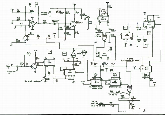
Fig. 10-57. Schematic diagram of the color bar calibrator.
With that out of the way, you should be moderately excited, at least.
But first the question is, "How does this accuracy manifest itself in my color TV set?" All color television receivers lock onto the color subcarrier signal, and, if the color set is tuned to a network program, its internal 3.58 MHz oscillator generates a replica of the atomic oscillator signal back at the network studio. This 3.58 MHz signal from the color receiver is not a substitute for the oscillator in the frequency counter. It is a calibrating signal that can be used to set the oscillator. In only 15 minutes, one can match the results of days of data gathered from the NBS radio stations WWVL or WWVB. In order to interface the counter oscillator with the TV set, a small box will have to be built (Figs. 1-57 through 1-60) containing 12 inexpensive ICs, a $1 color TV quartz crystal, 3 cheapie transistors and a few other simple components. This small box is called a color bar generator. All of its components fit on a 4" x 7" PC board.
Essentially, this box takes the 3.579545454 MHz network signal and phase-compares it with the 1.0 MHz, 5.0 MHz, 10.0 MMHz, etc., frequency standard or crystal timebase you have in your workshop.
The block diagram in Fig. 10-61 illustrates one of two ways the equipment is interfaced with the TV set. Basically, the color bar generator produces a wide vertical bar on the face of the picture tube simultaneous with receiving a network telecast.
With the crystal timebase oscillator of the counter coupled into the color bar generator, the bar generator's level control is adjusted for a comfortable bar presentation level. The bar will be moving horizontally across the face of the TV screen. If moving to the right, the counter oscillator frequency is high; to the left, it is low. Adjusting the counter crystal frequency in the proper direction will slow the horizontal movement of the bar until it stops moving. Pressing the momentary switch on the color bar generator positions the bar on the screen. Just keep pushing until the bar positions itself where you want it. Now, going back to the counter's crystal frequency adjustment, further corrections of the frequency will cause the spectrum of colors to roll through the bar presentation. If the colors are rolling from left to right through the bar, then the frequency of the oscillator is on the high side; if moving to the left, the converse is true.
When the colors are moving slowly through the bar, the frequencies or divisions thereof are on the same frequency, but not in phase with one another. (The frequency of the counter timebase is already much closer than one could ever adjust it by any aural beat frequency method.) Further adjustments in phase are necessary in an attempt to cause the rolling of colors to slow even further. When a single color can be retained for about seven seconds, the timebase accuracy has parts measurable in 10-8. If a single color can be retained for about 15 minutes, then you have attained a crystal timebase stability measured in parts in 1011. One thing to remember is that, if the crystal oscillator and associated circuitry does not have this inherent stability, then it will never be attained no matter how long a warm-up period is given the counter. However, one thing is certain: This
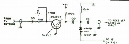
Fig. 10-58. Schematic diagram.
system will squeeze out every bit of accuracy of which the counter is capable. Now that you know what this device does, and if you have the appreciation of this advancement in the state of the art of frequency technology, your adrenalin should be running at top speed.
As stated earlier, the illustration in Fig. 10-61 shows how to interface the equipment by going into the antenna system of the TV set. This method has at least one drawback. Coupling the signal through the TV antenna causes the signal to pass through more of the TV circuitry than is needed, thus producing a visual beat note. This shows up on the TV screen as an annoyance.
A second method uses only the video circuits needed, eliminating this beat note. This method requires getting into the inside of the set and adding a small coupling capacitor, a length of RG-174 50[1 coax and a BNC connector. Essentially, you must tap into the TV chrominance bandpass amplifier stage. It in no way degrades the normal operation of the TV set. If you have the technical competence to expose the innards of your TV set, mother, father or spouse willing, then it is recommended you do so. Otherwise, the antenna input method will suffice.
What makes the color bar generator work is best illustrated by the schematic in Fig. 10-57. Let's see just how this thing takes an odd frequency like 3.57954545 and makes it harmonically related to a 10 MHz crystal and/or any submultiple, that is, 10 MHz divided by N where N = 1,2,3, up to 100. This allows one to compare frequency sources of many frequencies.
The crystal oscillator used in the frequency counter as a timebase reference or, for that matter, any oscillator used as a reference frequency ...
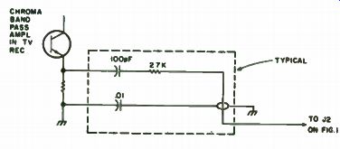
Fig. 10-59. Schematic diagram.
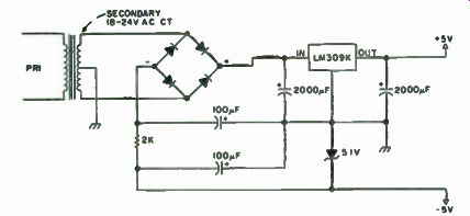
Fig. 10-60. Schematic diagram.
... standard, is fed into the J1 input to Q3. The signal is divided by 16 and then by 11, for a total of 176, and drives the base of Q1, which is a phase locked loop comparator.
The 741 operational amplifier (connected as an RC integrator) drives a voltage-controlled crystal oscillator operating at the color subcarrier frequency of 3.58 MHz. The other input to the comparator comes to the Q1 emitter from the loop output circuit. The output from the VXCO drives a 74123 one-shot circuit for pulse-shaping of the oscillator output.
Two signals are taken from the one-shot, and the positive-going transitions are coupled through a 7402 NOR frequency doubler, the output of which is fed into the inputs of a 8280/74176. Part of this signal is divided by two and fed back to Q1 for phase lock.
The result of phase lock is that you have a crystal-controlled oscillator operating at the subcarrier frequency phase locked to a local standard. This permits you to inject a signal into a television receiver and compare it to a network color subcarrier. The second part of the injected signal to the 8280/74177 binary counters is further divided by 7 and 13, providing a total ...
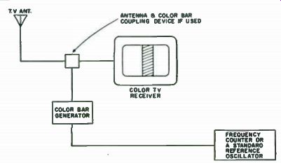
Fig. 10-61. Block diagram.
... division of 455. The resultant frequency of 15,734,265 Hz is equal to the horizontal oscillator signal of the color TV receiver. This will produce a stationary vertical bar on the TV screen. This horizontal rate signal is used, with the output of the modulator, to drive the receiver. The block diagram of Fig. 10-61 shows the signal being interfaced through the antenna terminals of the TV receiver. Using this method requires the addition of a single transistor circuit and a pair of terminals to accept the TV antenna. This additional circuitry connects between the TV antenna and then antenna terminals on the TV receiver. See the schematic in Fig. 10-58.
The second method does not require removing the antenna from the receiver and placing it onto the bar generator, but does require obtaining a schematic of the receiver so that a point in the chrominance bandpass circuit can be located. A typical chroma interface is shown in Fig. 10-59.
A 15 MHz oscilloscope will be helpful in determining that all of the ICs are operating and dividing properly. There is only one circuit in the unit that requires tuning, and that is the 3.58 MH crystal stage; C10 requires adjusting to produce doubling of the frequency at pin 13 of the 7402 IC. Check pins 4 and 13 of U3 for equal amplitude signal. Now connect the color bar generator to the TV set, tune in a color program, preferably a network program but not absolutely necessarily at this point and adjust the level control RI for an acceptable presentation of the vertical rainbow color bar on the screen. Adjust the 7-25 pF C 1 crystal trimmer capacitor until the movement of the bar slows sufficiently. This will place the crystal frequency so that it is within range of the 741 op amp voltage swing and so that the varicap can lock the crystal on frequency when the local frequency standard approaches phase resonance.
A VTVM at pin 6 of the 741 op amp is another good test point.
Variations of C1 will cause changes at pin 6. When everything is working properly, the device for calibrating the frequency standard is ready to be used.
Everything is now ready for that very exciting moment, except for an extended period of warm-up time for the local standard. This period depends upon how accurate a calibration one is looking for. Obviously, if you are seeking the ultimate, then it is recommended that the oscillator, once turned on, remain on indefinitely. For a starter, I would suggest a 24-hour warm-up be considered as minimum. Then start a program of measuring the frequency every 24 hours, preferably at the same time each day. The stability will be erratic for about a week. If a careful record is kept, you will note that this stability will improve over the next 90 days, when it will settle out with a predictable aging rate thereafter. So there is no misconception at this point, it should be understood that, if the standard oscillator is one of mediocre quality (has no oven, not a low drift crystal cut, etc.), then one cannot expect accuracy of better than perhaps parts in 1.0-7 or worse. In this case, the unit should be warmed up for a period of five to 24 hours, calibrated as best you can, and used as soon thereafter as possible. If the crystal has an oven, the expected accuracy will be better. The quality of the crystal and the oven are of major consideration.
--
Next: Oscilloscopes