The Benefits of Sidetone Monitoring
Sidetone is used in amateur circles to denote a tone from a CW keying monitor. But the term comes, of course, from the telephone industry, where a certain amount of the voice energy fed into the microphone unit of a telephone handset is deliberately coupled to the receiver unit in the headset so a person can barely hear himself talk. It was determined that transmission efficiency was improved by this scheme and a person using a telephone tended to maintain a steadier, more level talking level-especially in a slightly noisy environment. The method must have some value, since, besides in the telephone system, one will find audio sidetone employed in various commercial radio receivers, military transceivers and aircraft communications transceivers. This is in spite of the fact that these transceivers also employ various advanced forms of speech processing designed to keep the average modulation level as high as possible.
Amateurs might also consider the value of using audio sidetone in both mobile and fixed station installation. The use of such sidetone is mainly possible where a handset is used or a microphone/headset combination is employed. Otherwise, there is the possibility of audio feedback taking place unless a good directional microphone is used while the audio sidetone is monitored via a loudspeaker.
Simple Methods. A few simple methods for making the necessary audio sidetone interconnection in a station setup are as follows:
• If a separate transmitter and receiver are used, one can make an interconnection between the microphone amplifier stage in the transmitter and the audio preamplifier stage in the receiver. This should be done after the volume control in the receiver and utilizing a separate potentiometer to control the level from the microphone amplifier output in the transceiver. Figure 12-1 shows the basic idea. The audio stages in the receiver must remain activated during transmit periods for this scheme to work or the receiver transmit/ receive function suitably rewired to accomplish this. A relay is used to break the audio side-tone circuit when in the receive mode, since feedback can easily result if the high receiver loudspeaker output level in the receive mode gets back into the microphone circuit.
• If a transceiver is used, it may or may not be possible to utilize a scheme similar to the above between the receiver and transmitter portions of the transceiver. Some transceivers utilize complicated switching schemes for transmit/receive functions and the dual use of the low level audio stages both in the transmit function (as microphone amplifiers) and in the receive mode (as preamplifier after the product detector stage). In most transceivers, however, these functions are kept separate and one can switch the receiver section audio amplifier stages, via a relay, to pick up the output of one of the microphone preamplifier stages on transmit. A separate potentiometer should be used to control the level being fed into the receiver section audio amplifier stages and this potentiometer serves as the audio sidetone level adjustment.
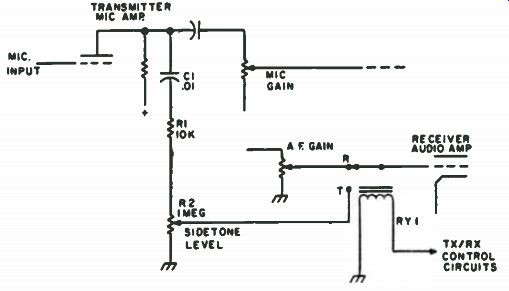
Fig. 12-1. Typical audio sidetone interconnection between separate transmitter
and receiver or sections of a tube-type transceiver. The only added components
are C1, R1, R2, and RY1.
The simplest scheme to achieve audio sidetone monitoring is via a separate small amplifier which is used between the microphone and the station loudspeaker or headset and is energized only during transmit periods. Any one of the number of simple amplifiers can be used, such as the solid state PA amplifier modules available from Lafayette Radio or Radio Shack for about $3. Although called PA modules, these modules will not exactly create enough undistorted volume to disturb the household. However, they are very suitable for audio sidetone purposes since they have a high impedance input which can be bridged across any microphone output without greatly affecting it, and their low impedance output can be used to drive either a loudspeaker or a low impedance headset connected across a receiver's output. At the low levels needed for audio sidetone, monitoring, their distortion is very low. They require Yi volts for operation, and this can be obtained in tube/type transceivers by a simple half wave rectifier and filter across the filament line. Figure 12-2 shows a typical arrangement. For mobile transceivers they can be powered via a dropping resistor directly from the battery line.
The secret to obtaining maximum benefit from audio sidetone monitoring is in the adjustment of the sidetone level. You have to trick yourself, the same as the telephone company people do! Pick up your telephone and listen for the audio sidetone level as you speak to another party. It has been carefully chosen, as you will be inclined to speak up consistently rather than whisper into the hand set. If the sidetone level were too loud, you would be inclined to speak more softly. If it is too comfortable to hear, you would be inclined to become intrigued with the reproduction of your voice, but not necessarily inclined to maintain a steady voice level. The sidetone level has been deliberately chosen so you can just hear it, and this is the adjustment to make for monitoring the audio sidetone level in a station. After a while, you will become unaware of the sidetone level, but you will try to speak at a consistent output level that allows you to detect the presence of the sidetone.
Audio sidetone monitoring is a relatively simple accessory to add to any station. The simplicity of the idea has probably been obscured by the usage of so many other speech processing devices such as audio compressors and clippers. However, if one can add only one or two dB more effective transmission efficiency to a station by audio sidetone monitoring and completely without any added distortion of the modulated signal, the idea seems worthy of a try.
Design Your Own QRP Dummy Load
A dummy load can prove to be a handy little gadget when it comes time to tweak-up the final in your handie talkie, QRP rig, or even CB set.
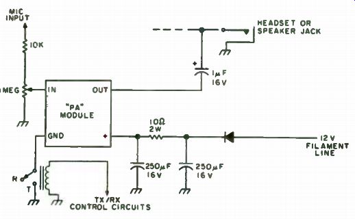
Fig. 12-2. Use of an inexpensive PA module amplifier provides audio sidetone
with a minimum of circuit modifications.
Unfortunately, there doesn't seem to be anything on the market that lends itself to the task, unless you're willing to invest in an expensive kilowatt model. The only way to get around it is build your own, an easy accomplishment with a little forethought and a handful of components.
Choosing the Resistors. Ideally, the resistors in a dummy load should act purely resistive (no reactance) over the frequency range they are going to be used. The only inexpensive resistors that come close to meeting this requirement are the carbon (composition) type. Wirewound resistors, al though cheaper and available in higher wattage values, exhibit too much inductance and are bothered by the skin effect. By contrast, carbon resistors are less subject to skin effect problems, so their resistance stays fairly constant as the operating frequency increases. In carbon resistors, reactance is mainly due to inductive effects in the leads and stray capacitance between the leads and nearby metal. These effects remain negligible up to around 100 MHz providing that the resistors are properly mounted and have values greater than 25 ohms.
------------------
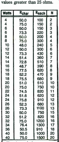
Table 12-1. Dummy Loads Using
Standard 2W Resistors ---------
The above design values will not result in a mismatch greater than 1.1:1 even when the tolerance is worst case.
------------------
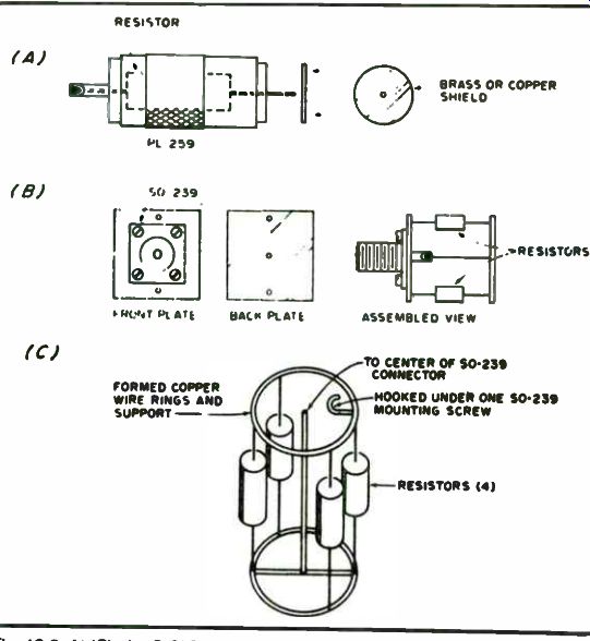
Fig. 12-3. At (C), the S-239 connector is mounted in the can lid. Make sure that the bottom ring does not make contact with the can.
Proper mounting dictates that leads should be kept as short as practical, and that there should be some separation between adjacent resistors Design. Because carbon resistors capable of handling more than two watts are expensive and difficult to locate, the only convenient way t achieve high power dissipation is to use several resistors in parallel. This increases reactive effects, but it offers greater power dissipation as a acceptable trade-off, unless you need an extremely accurate dummy load Also, it should be remembered that the power rating of resistors is continuous free air rating, so for short duty cycles, a dummy load can easily stand more. For example, with the 33 percent duty cycle of SSB the power rating may safely be increased by three, while the 50 percent CW duty cycl will allow an increase of two. A good rule to follow is to touch the resistor occasionally. If they are too hot to handle then they are dissipating too much.
The actual design of the dummy load is accomplished by starting with two parameters, the desired total power dissipation and the desired characteristic resistance. Assuming that all resistors have the same values and power ratings, the following equations may be used for designing a multiple-resistor dummy load:
Number of resistors needed = Desired power dissipation of dummy load Power rating of each resistor, and Value of each resistor
= Total resistance of dummy load x Number of resistors needed
All too often the calculated value for each resistor will not be a standard resistance, a factor that will complicate matters. Table 12-1 helps to sneak around this problem by offering values based on the standard two watt resistors.
Construction. The actual construction depends upon the number of resistors that the above equation tells you are needed. If you can get away with just one, whether it be a 1/4 or 2 watt, then the design in Fig. 12-3A should do the job. Here, the resistor is soldered inside a PL-259 connect, with a small metal plate soldered to the end as a shield.
For higher power operation, the circuit in Fig. 12-3B allows compact mounting for 20 resistors or more. In this circuit, two copper or brass plates are used for mounting to eliminate capacitive coupling between adjacent leads. After the SO-239 connector has been mounted, a series of small holes are drilled in both plates for the resistors. A hole is also drilled in the center of the back plate and a wire soldered between the center conductor of the coax connector and the back plate itself. As always, leads should be kept as short as possible.
If shielding is what you need, and even higher power dissipation, then the circuit in Fig. 12-3C may be installed inside a pint or one half pint paint can. Transformer oil can be added to increase the short duration power handling capacity by a factor of three or four. A note of caution however: Don't use motor oil-because of its lower boiling point, it has a nasty habit of blowing off can lids, and sending hot oil all over the place.
In the interest of accuracy, it's worth the extra money to invest in 5 percent resistors for these circuits. This will give a tolerance of ±2. 5 ohms for a 50 ohm dummy load, which results in a mismatch of only 1.05:1.
Fig. 12-4. Bottom view of the can.
Home-Canned Dummy Load
In today's times of high prices, it is nice to know that home brew dummy loads are still within the price range of the poorest amateur. Half gallon gallons can be constructed for less than $3 using readily available materials.
One-gallon paint thinner cans were prepared for the project by cutting off their bottoms with an ordinary can opener (Figs. 12-4, 12-5 and 12-6). This was followed by a thorough washing and drying procedure to remove any trace of the flammable contents. Next, twenty 470-ohm, two-watt 10 percent resistors ( 10 for each load) were sorted between two of us so that we had equal numbers of high and low values. This gave us parallel combinations that were very close to 50 ohms. Each group of 10 was then soldered between two 3" x 3" pieces of 1/16" brass plate predrilled to accept nine resistors in a 2"-diameter circle with the tenth one in the middle.
A hole was then punched on top of the can to accept a suitable connector. In this case, a flange-mount SO-239 was the choice. The flange of the connector was soldered to the can to make an oil-tight connection. The rear of the connector was also epoxied over to prevent oil seepage through the center conductor.
The resistor network was then mounted in the can, supported by a 2" length of heavy-gauge wire soldered from the center pin of the connector to ...
Fig. 12-5. Brass plate.
Fig. 12-6. Resistor network.
... one side of the resistor assembly. Four pieces of copper braid were soldered to the bottom of the resistor network at each corner and then soldered to the can for support and to provide a good ground plane.
The can was sealed by cutting a piece of 1/16" copperclad PC board approximately 1/4 " larger than the base and soldering this to the bottom of the can.
Testing the load on a Hewlett-Packard network analyzer model 8407A showed that the loads were purely resistive at 50 ohms up to 32 MHz. The can was filled with a gallon of 30- or 40-weight motor oil (the cheapest brand available). The dummy load was designed for transmitters in the 200-watt class, but it is able to take at least twice that power. It is advisable to loosen or take off the cap of the dummy load when in use to vent any expanding oil or fumes that may come off when the load is used at high power.
Instant SWR Ridge VSWR measurement is widely used by radio amateurs for adjusting and matching their antennas. One hobbyist saves a lot of walking and tunes his antennas. He started out with a model 190B Tektronix constant amplitude signal generator, which is easy to obtain now on the surplus market. He modified the signal generator slightly, built a 50-ohm resistance bridge and merged them to come up with an extremely stable and accurate vswr bridge.
If you don't want to modify your generator, you could build only the resistance bridge portion.
The 190B signal generator is perfect for this vswr bridge because of its constant output level, which means that once the incident (forward) voltage is set, you can tune a very large frequency band without needing to readjust every few kilohertz or so. And there are other advantages. The frequency range covers 160 through 10 meters. With this hobbyist's generator-bridge arrangement, everything is complete in one package, so it's handy to use.
Because of its low output level, there is no QRM radiated into space.
The following steps describe how to modify the signal generator and install the resistance bridge:
• Remove the external attenuator pad and its socket from the unit.
(Note which pins the wires are on.) Fabricate a 1 1/2"-square aluminum plate to mount an SO-239 rf socket, and attach the socket to the unit.
• Drill a 5/16" diameter hole midway between the power switch and the SO-239 rf connector. Refer to Fig. 12-7. This hole will be for the vswr function switch.
• Remove V50, a 12AU7 tube used as the meter amplifier, and discard it.
• Build the 50-ohm resistance bridge according to the schematic shown in Fig. 12-8. Caution should be used in the wire dress because the frequencies will range up to 50 MHz.
• Install the resistance bridge in the 190B signal generator.
• Remove the wire from pin 3 of the attenuator socket (blue/white/ yellow). It was a heater voltage supply on older units.
Fig. 12-7. Completed vswr bridge using modified Tek 190B generator.

Fig. 12-8. This is the circuit of the 50-Ohm resistance bridge. R1 should
match R2. RX should be trimmed so that incident (fwd) voltage equals reflected
voltage.
The 1:1 and 2:1 positions of switch Si are simply 50-Ohm and 100-Ohm resistors to ground. When switched in, these positions give a quick self-check of the unit. D3 and D4 are the feedback diodes for the Tektronix 190B generator. All diodes = 1 N270.
• Ground the wire from pin 2 of the attenuator socket (white/red) at the newly installed SO-239 socket. The coax shield also connects at this point.
• Connect the wire from pin 1 of the attenuator socket (white/blue) to the resistance bridge.
• Replace the 500-ohm meter-zero pot with a 10,000-ohm pot. Re wire as shown in Fig. 12-8.
• If desired, the existing meter can be replaced (Fig. 12-7), but it's not necessary.
• Install the four-position swr function switch in the 5/16" drilled hole, and wire to the resistance bridge as shown in the schematic of Fig. 12-8.
• A chart for determining vswr is shown in Fig. 12-9.
Copy it or cut it out and tape it to your unit. Calibration is simple. After the unit is complete, turn it on. Do not have a load connected to the coax connector. Adjust the incident voltage (INC) for full scale, then switch to the SWR position. The meter should read the same in each position. If it doesn't, trim RX until the meter reads the same. Now, switch to the 1:1 position. The meter should fall to zero, indicating a balanced 50-ohm load into the bridge. Switch to the 2:1 position.
The meter should read approximately 30 percent of full scale, indicating about 2:1 vswr. If all this happens, box it up.
Now the beauty of this device takes hold! Because the generator's output is constant, when you vary the frequency dial, the meter will track your vswr curve over the entire amateur band you're testing. The first thing you will notice is that somewhere there is a dip, which is the resonant point of the antenna. The amount of dip indicates the impedance (in vswr). This dip will then give the necessary clue for any adjustments.
There are several possibilities for the generator-bridge. A 500-ohm pot could be substituted for the 50-ohm Ra resistor togive the bridge an impedance range of 0-500 ohms, or a complete LC impedance bridge could be installed for maximum use of the generator-bridge. Old coax can be tested with the generator-bridge by shorting one end of the piece being tested and measuring the vswr. The loss in decibels can then be calculated.
If nothing else, the generator-bridge is a very good test rf generator to have in your ham shack. You can adjust beams with gamma matches, verticals (both trapped and mono-band), dipoles, inverted vees and even mobile antennas using this generator-bridge.
UHF SWR Indicator
There are many inexpensive standing wave ratio indicators that are listed as good up to two meters and do function well. At frequencies above approximately 150 megahertz the results leave something to be desired.
There are several valid reasons why the swr indicators are inadequate.
In order to have good sensitivity at the lower frequencies (80 meters), the coupling loops used for forward and reflected wave samplings are usually 6" long, and are close-coupled to the center conductor of the transmission line.
If the sampling loops are shortened and loosely coupled, then the sensitivity for the lower frequencies is greatly reduced.
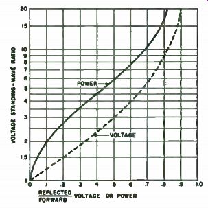
Fig. 12-9. Chart for finding vswr when ratio of reflected to forward voltage
is known.
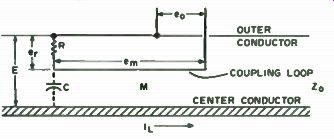
Fig. 12-10. Distributive capacity element.
Another reason for poor operation is that the coupling loops required for low frequency operation represent almost a quarter wave at the three quarter meter band (---- 500 MHz). Distributed capacity between the long coupling loops and the inner coaxial conductor is excessive.
The diode rectifier characteristics become more important at the higher frequencies. The position of the pickup loops with regard to spacing, direction and concentricity must be very carefully aligned if their electrical characteristics are to be as similar as possible. Once aligned or positioned, the loops must remain rigidly affixed if a level of confidence in the indicator is to remain.
If the coupling loop is to be a small percentage of a wavelength ( 1/20 or about 5 percent), a length of 1" is about the maximum to be considered. If the indicator is to be used with low power transmitters ( 1/2 to 2 watts), the loop should approach the 1" length. For high power transmitters, the loop may be as short as 1/2". This is that portion of the loop that is parallel to the coaxial center conductor.
The coupling loops form a circuit with a resistor such that the mutual coupling is positive (+) in one case, and negative (-) in the other. The same effect could be obtained if a single loop was used for sampling, then rotated 180 degrees and then sampled. Inspection of the equations that follow will show this is taken into account.
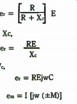
That portion of the loop parallel to the center conductor and the resistor form a third component, the distributive capacity element (Fig. 12-10). The output rf voltage eo is made up of e, and e.. A voltage divider is formed by distributive element C and R. Then,
{_±2 _ E R + X,
and if R is much less than Xc,
RE e, = X, and since jwC equals 1/Wc,
e, = REjwC
e_r = I Ejw (±M)1
by induction.
The sum of e, and em is (factoring out jw)
eo = jw ( CRE ± MI)
The directivity of the indicator, its ability to discriminate between the forward and reflected wave components, depends upon the relationship CR
= ma., where Zo is line impedance.
Substituting for CR, e = jw
( EM ± MI) = jwM ( E ± I) n Zn
Another relationship must be established before again substituting in the rf output voltage equation for eo. It is important to note capital letter E is used to designate the line voltage.
The voltage E at any point on a transmission line is the sum of the forward and reflected voltages, or E = ef + e, It should be remembered that e, during the next few equations represents the reflected voltage; it should not be confused with er, the voltage across resistor R. Then,
= er e, Zo Zo
The minus sign is because the reflected wave travels in the opposite direction.
I = It + h where Ir = - er Z o
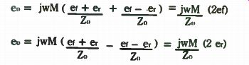
There are two cases to consider: (a) when the resistor is toward the load; and (b) when the resistor is toward the source. So, substituting for E and I in the eo equation for each case,
= jwM ( et + e, + et - er ) = jwM (2ef)
Z0 Z0 Zo eo = jwM ( et + er _ e t - e r ) jwM (2 er)
z o Zo
The equations show that the rf voltage from the loop before rectification is directional and proportional to the voltage in the transmission line (due to the forward and reflected wave respectively). Figure 12-11 shows that even though Es is zero, E, and Er are still present.
The frequency limits of the indicator are exceeded when resistor R is not very much lower than distributive element C, and when mutual inductance M is not nearly purely reactive.
Construction Details. A length of copper water pipe is used for the wave sampling section of the transmission line. The use of tubing helps to maintain a constant line impedance, keep the inner field distortion to a minimum and radiation leakage down. For the center conductor, a #7 or a #3 AWG copper wire will provide a line impedance of 75 or 50 ohms, respectively. Thin wall model builder's brass tubing of equivalent o. d. was used in constructing the indictor for this project (Figs. 12-12 and 12-13). To accommodate the sampling loop, drill three Vs" diameter holes 3/4 " apart in the copper tubing. Form the insulated sampling loop, and insert the leads through the three holes. Single conductor, tinned, #22 AWG, with thin wall insulated sleeving added, maintains its shape better than stranded wire for the sampling loop. With 3/4 " lead protruding out of each hole, temporarily bend each load so as to make the loop captive. This will help ...
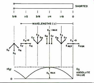
Fig. 12-12. UHF swr indicator.
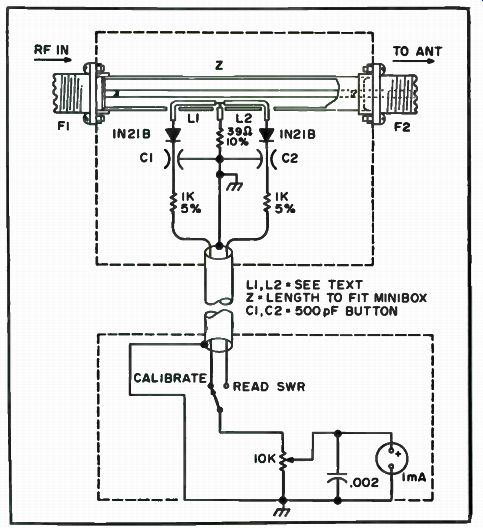
Fig. 12-11. Diagram of voltage standing waves on transmission line.
... prevent the loop from slipping out of position during the fastening of the end fittings.
Solder the end of the conductor selected for the center lead to a mica-filled SO-239 coaxial fitting. Other types of fittings such as the N or the BNC may be used, but different mechanical arrangements will be required.
The other SO-239 fitting requires modification if no other holes are to be drilled in the outer copper tubing. The modification consists of removing the center pin of the connector. Depending upon the brand and vintage of the connector, some pins are removable by a simple "C" ring clip. Others have a rolled-in ridge for fastening, etc. After the pin has been removed intact, use a drill to establish clearance so that the pin can be freely inserted from the rear side of the connector.
Temporarily slide the copper tubing and loop subassembly over the center conductor with the fitting previously connected to one end. Deter mine through inspection the proper length the center conductor should be to permit the recently removed center pin to slide into the fitting with the slightly enlarged hole without protruding. The fitting must also butt against the end of the outer copper line. After the proper length has been deter mined, solder the pin to the center conductor.
Make two rings about 3/4 " long by cutting the ends off a standard copper elbow or coupler section. With all burrs removed, the rings, line and end fittings are ready for soldering. A 250 watt gun or iron will speed the assembly.
If the assembly is to fit inside a ready-made minibox, the box selected and the length of the line should be compatible. The box will help keep the sampling loop from being disturbed once positioned. A 3/4 " hole in each end of the box is required, with one hole slightly elongated, so that when the box ends are sprung back slightly, the line assembly may be inserted. The assembly of the rest of the components is straightforward.
To adjust the loops, the line should be inserted into a transmission line, first in one direction and then the other until the two sets of readings are almost identical (except reversed). Once obtained, place a drop of quick drying model cement at each of the sampling loop exit leads, without disturbing their placement. Figure 12-14 is a typical meter scale.
If the 1N21Bs and resistors have been matched even with the humble ohmmeter, and the parts layout is reasonably symmetrical, little effort should be required to position the pickup loops.
The line and meter may be mounted together in a larger single box if desired. It may also be desirable to use a set of connectors in the interconnecting cable to insert an extension cable when needed to provide remote readings during backyard antenna matching sessions.
The directivity of this indicator, and its ability to discriminate between forward and reflected wave components from 50 MHz to 500 MHz (and maybe even higher), is excellent. The use of type N fittings is recommended for frequencies above 500 megahertz.
Simple VHF Monitor
This little converter, when used with an inexpensive portable transistor radio, will monitor a wide range of VHF frequencies. It can be built in a few minutes using junk box parts. Even if the parts have to be bought, they will cost only a few dollars. It doesn't provide communications receiver quality, but it is useful when tuning up a transmitter or for general coverage reception. It mounts next to the ferrite loop of the transistor radio to make up a complete receiving system. Reception over a wide range of frequencies is possible by altering the tuning coils. The components specified here cover the range of about 120 to 150 Mhz. This range provides a lot of fun in ...
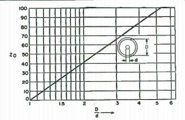
Fig.
12-13. Ratio of diameters to line impedance.
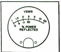
Fig. 12-14. Typical vswr meter scale.
... listening to aircraft radio communications, the 2 meter ham band and other services.
The circuit (Fig. 12-15) is that of a regenerative converter. The incoming signal, tuned by the tank coil L-1 and capacitor C-2, is mixed in the transistor with an oscillator frequency controlled by L-3 and C-7. The difference frequency is adjusted to fall in the standard broadcast band.
The converter is built on a small piece of perforated board. Parts layout is not critical. However, all leads should be kept as short as possible and the oscillator and input tank coils should be mounted at right angles to each other. The completed assembly is mounted in a small open backed metal box to minimize the effects of hand capacitance. Tuning is accomplished by drilling a 1/4 " hole through the box in line with the adjustment screw on the oscillator tuning capacitor. A small piece of 1/4 " wooden doweling is then cemented to the tuning screw with a drop of Eastman 910 (or equivalent) cement.
A small dual gang variable capacitor could be used but would be more expensive. Tuning of the input tank circuit is very broad and does not require adjustment after it has been initially set. A hole could be drilled in line with C-2 to permit peaking, using an insulated screwdriver, after the unit is packaged. A BNC connector or RCA type female phonograph connector is mounted at the top of the box for connecting the antenna. Good reception on local signals was obtained with a piece of # 14 wire 19" long for the antenna.
Coils L-2 and L-4 can be 100 microhenry VHF rf chokes, or if you don't have any in your junk box you can use TV peaking coils or simply scramble wind about 20" of fine wire on a 100k 1/4 watt resistor.
The completed converter is fastened to the back of the radio using vinyl tape or rubber bands. Placement is not critical, but try to locate coil L-3 as close to the ferrite loop as possible. Connect the battery and turn the converter on. Tune the radio until a loud hissing sound is heard. Typically this will occur on at least two spots on the dial. Tune the receiver to the loudest hiss. Turn the converter power off to be sure that you are tuned to the output of the converter. Next tune in a signal with C-7 and peak C-2 for maximum signal strength.
Tuning is best done with C-7, although a certain amount of peaking can be done with the transistor radio tuning. As with most regenerative type devices, a high level signal can readily capture the tuning. Although the converter has limitations, you can get excellent reception from aircraft over 200 miles away, and from ground stations up to 30 miles away.
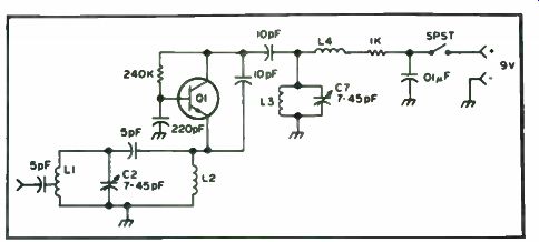
Fig. 12-15. Schematic of low cost VHF monitor. L-1: 4 turns #22 wire on 1/4'
diameter form. Center tapped. L-2, L-4: See text. L-3: 4 turns #22 wire on
1/4' diameter form. Q-1: NPN VHF transistor 2N2222 or equivalent.
VHF Noise Snooper
Are you quite sure that nothing can be done about that noise level at your QTH? Just one of the problems with noise is its frequency content.
Here is a new approach to noise tracing, using a piece of equipment you most likely already have.
Simply cut or unsolder one end of either of the FM detector diodes in an AM/FM portable, and you have an ultra portable, ultra sensitive noise detector. A schematic is usually unavailable for these Japanese sets, but you can usually spot the diodes sitting side by side between the last i-f cans and the audio transformers. Shorting one diode will probably work as well.
First find a blank spot between stations and start out. You'll probably have to walk to keep out all tire noises. As you move, the noise will go in and out like airplane flutter, slowing down and getting steady when you are very near. Then you can point the end of the whip at the noise source for a null.
One noise was found so accurately that the vertical position on the pole was pinpointed for the power company linemen.
Of course there are other problems. When you rid the neighborhood of all those power leaks, you really notice the cars.
RF and Modulation Monitor Around most ham shacks, several uses can be found for a simple rf and modulation monitor. This one is little more than a glorified crystal detector, but it monitors outgoing rf, aids in the tune-up of transmitters and antennas and lets you hear how your transmitted signal sounds.
Of course, single sideband -if the carrier is properly suppressed- will sound through this monitor like you're talking with a mouthful of wet cement. Amplitude modulated signals should sound clean and natural.
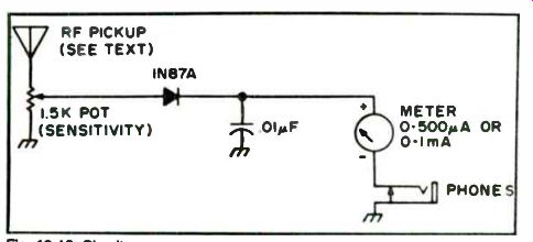
Fig. 12-16. Circuit.
This circuit (Fig. 12-16) can be built in a small phenolic box measuring 3 3/4 " x 2 3/4 " x 1 3/4 ". A metal minibox also can be used. The rf prove is 5 feet or so of #22 enameled copper wire folded and taped into a whip about a foot long and soldered to a phono plug. At low frequencies and low power levels, a longer piece of wire may be necessary for sufficient rf pickup. Almost any germanium diode should work, but a 1N87 gives higher output than a couple of other general purpose diodes.
Build a Simple Field- Strength Meter with Class The manual for one rig suggests that a " better procedure" for loading it up is to use an swr bridge on forward or a field strength meter to peak plate and loading controls for maximum output power. The field strength meter seemed the easy way out, since a bridge costs $ 15. The meter would cost next to nothing to build considering the abundance of gear that is probably in your junk box. Take the junk box approach to measure output power.
When you go scrounging parts for this project, remember about the choke. Anything that will choke rf works. So, substitute freely, but don't change from a diode to a resistor.
The design is standard (Fig. 12-17), but the antenna is quite unconventional. Instead of using a piece of 12 gauge bare copper or coat hanger wire, we used 22 gauge tinned copper wire bent into the form of initials.
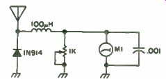
Fig. 12-17. Schematic.
-------------

1 diode, 1N914 or just about anything else
1 50 uA meter
1 rf choke
1 pot, 1k or thereabouts
1 0.001 uF capacitor
1 mini box
1 banana plug
1 banana jack
2 shouldered washers
Plenty of twenty-two gauge wire
Table 12-2. Parts List.
---------------------
Construction. Select the amount of wire you feel necessary to complete your initials or whatever. Straighten the wire with a vise and a pair of pliers.
Starting at the top of the left initial, make a bend to form the beginning of the antenna. Try to use one continuous piece of wire to make the antenna. To insure this, draw your idea on a piece of paper first. If you use one piece of wire the antenna will look a lot better, and you will eliminate having to solder on extra pieces of wire. The joints make bulges in the antenna which just don't look as nice on the finished meter. Solder a few spots to hold this thing together. You can also attach a banana plug.
With the antenna done, we built the guts of the meter. The easiest way to go is to mount the pot and use its terminals as tie points. The wiring is the easiest you'll ever do and is almost impossible to mess up.
Conclusion. Taking a lead from modern art, you can make just about anything for an antenna on your FSM. You've got to admit, now that we have an alternative, that bare copper does look a bit uncouth! This meter may not be the best or the smallest, but it does have class! For the parts list, see Table 12-2.
--
Next: Bench and Lab Supplies