AMAZON multi-meters discounts --- AMAZON oscilloscope discounts
Build a Simplified, Sensitive Millivoltmeter
Here's a practical instrument suitable for home construction which is based upon an integrated circuit (NATIONAL type LM 4250 C). Switched ranges of 5 mv to 500v are provided (Fig. 3-1). Construction. Layout has not proved to be critical in the prototype but input leads and associated switching have been kept compact; 2 percent tolerance resistors have been used throughout. Initial zero adjustment on the 5 mv range is set by selection of Rb in association with potentiometer R2 which is used for fine control. No zero drift has been observed on the prototype even on the most sensitive range.
An internal calibration check is provided on the 5v and 50v ranges by a pushbutton connection to the positive supply rail. This facility is used to adjust the meter deflection initially to 1.4v on the 5v range by means of pre-set resistor Rm. The value of the associated fixed resistor rf may also be varied if found necessary to suit the internal resistance of the meter used.
A miniature main switch serves to reverse the input polarity when required. The power supply comprises two mercury-button type cells (ER 675) contained within a small paxolin tube, spring loaded to maintain contact pressure. Other options are possible, of course. Consumption is minimal, being approximately 60 microamps for full-scale deflection. The unit is housed in an aluminum die-case box.
Input impedance is approximately the value of Rc for the range concerned, shunted by the input-lead capacitance (approximately 50k to 5 megohms, according to the range used). Overload protection is provided by two back to back signal diodes. Repeated application of 30v DC on the 5 mv range has had no detrimental effect on the prototype. External shunt resistors may be used to monitor DC currents down to quite low values.
Figure 3-2 gives examples scaled for measuring 5 microamp and 0.5 microamp full scale deflection on the 5mv range.
Rf may be measured by the use of a suitable probe (Fig. 3-3). The approximate input impedance of this device is 6k at 2 MHz, falling to 1k at 25 MHz. The probe is usable to about 100 MHz.
Application. Since the instrument is sensitive and self-contained, it lends itself to a variety of tasks, some beyond the means of conventional multimeters. The very low power consumption means that battery life is very near shelf life.
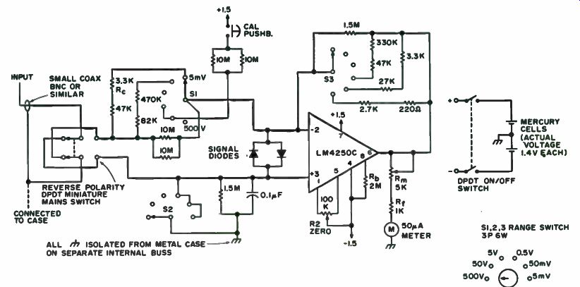
Fig. 3-1. Circuit diagram. ALL ISOLATED FROM METAL CASE ON SEPARATE INTERNAL
BUSS. MERCURY CELLS (ACTUAL VOLTAGE). REVERSE POLARITY. PDT MINIATURE MAINS
SWITCH CONNECTED TO CASE
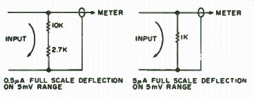
Fig. 3-2. External shunts.
The ability to read currents of less than a microamp enables diode and semiconductor device reverse and leakage currents to be read. With the millivoltmeter suitably insulated EHT tube currents can be measured (CRTs).
A Battery Voltage Monitor
A device introduced by Litronix, Inc., has wide application as a voltage monitor in all types of battery-operated equipment. The RCL-400 Battery Status Indicator is a current-controlled LED which has a voltage sensing integrated circuit incorporated into a small LED package.
The only additional circuit component necessary to build a voltage monitor is a suitable zener diode, or string of forward biased diodes, to bring the device into its normal operating range. The RCL-400 is designed to turn on at 3v and off at 2v; thus normal operation can be provided by selecting V2 = Vcc 3v ( Fig. 3-4).
When Vcc drops to Vz + 2v, the LED is switched off by the internal IC voltage sensing circuit to give a low voltage indication. Since the device has a relatively constant current demand in the on region (- 10 mA), the zener power rating need only be 1/4 w for most battery-powered equipment. One precaution is necessary: You must be sure that the voltage across the LED does not exceed 5v ( its maximum rating). For low voltage IC circuits using a nominal 4.5 y battery pack, the required value of Vz is only 1.5v. It is easy to obtain this value by simply substituting a pair of silicon diodes in series with the LED. Fig. 3-3. Rf probe.
The Easy Ammeter
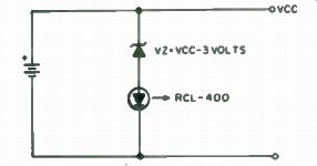
Fig. 3-4. Schematic.
Have you ever wanted to measure the current flow of a particular transistorized device that is sitting on your workbench? Too many people sometimes bypass this important step due to the inconvenience of breaking the power lead and then having to resolder it again.
Here's a really easy way to measure current flow. Since most transistorized gear is powered from a battery pack of some sort, all you have to do is stick a piece of double-sided printed circuit board between any two batteries, as shown in Fig. 3-5.
Touch the two meter leads to each side of the PC board and there you have it-instant current reading without cutting and soldering any wires.
Adding An Ammeter to Your Car
In an effort to simplify the operation of automobiles, most car manufacturers have, for many years, incorporated an alternator indicator light on the instrument panel in lieu of the ammeter of days gone by. While this indicator light requires less attention while you are driving, it does not give you complete information on the state of your electrical system.
Perhaps your car should have an ammeter. Sometimes over a period of time, the output of an alternator steadily deteriorates and does not charge the battery properly. Eventually the battery can completely discharge and leave you stranded.
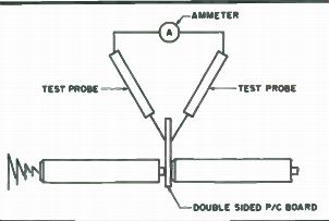
Fig. 3-5. Circuit board between two batteries.
You have to be very careful installing a new alternator because you could accidentally ruin a relatively new battery. For example, if during the entire time that the alternator was failing, the indicator light on the instrument panel would turn off during normal driving it would indicate that the alternator was "charging" and apparently, according to its indication, there would be no problem. It would be better to have some type indicating ammeter which would indicate the state of the system as to whether the battery was being charged or discharged. This section describes a method of installing an ammeter into your existing automobile system without any changes or modification to the existing system and at a very low cost. In fact, it is so easy and inexpensive to incorporate it into your system that you shouldn't be without one, especially if you operate mobile radio equipment which adds an additional drain to your car battery.
Advantages. This system has several advantages which make it attractive for an amateur to install in his car. These advantages are:
• All leads are at ground potential, so there are no problems with shorts in the system or the necessity of fusing the conductors.
• No heavy currents pass through the indicator, so small conductors may be used.
• Although the system makes use of shunt resistance to measure the current, a unique method is used so that no additional voltage drops are added into the present electrical system.
• It is very easy to add to your existing electrical system-no changes in existing wiring.
• The ammeter circuit can easily be adapted with a switch and resistor to read system voltage.
• It is inexpensive to install and depending on the type of meter movement you install, the cost can range anywhere from $1.50 to $7.00. With these advantages, certainly many amateurs will want to install an ammeter to their car electrical system to monitor the battery charging rate.
Typical Electrical System. Referring to Fig. 3-6, a diagram for Ford Electrical System is presented. This system incorporates an electromechanical voltage regulator and is the type used in many cars (although other systems such as General Motors are similar). As you can see, the alternator consists of a stationary 30 stator winding in which the output goes to a set of diode rectifiers. These diodes are arranged in such a manner that the output at the battery terminal of the alternator is always positive. There is a rotating field which excites the stator winding during normal operation.
As you can see, the alternator is always connected directly to the battery through a terminal block. It is at this point that the other electrical loads in the car are connected. The neutral from the stator winding is grounded through the field relay winding in the voltage regulator and its contacts are normally open. When the ignition switch is turned on, a certain amount of voltage from the battery is connected directly to the field through the charge indicator light on the instrument panel. After the engine is started, and the alternator is producing current, the stator current flowing through the field...
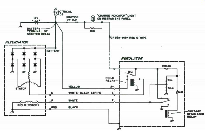
Fig. 3-6. Ford electrical system with electromechanical type regulator. (Other
electrical systems are similar.)
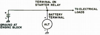
Fig. 3-7. Simplified diagram excluding the regulator.
...relay winding pulls the contacts down which in turn bypasses the indicator light on the instrument panel. In other words, as long as the alternator is producing current of sufficient magnitude to hold the field relay contacts closed, the charge indicator light will be off, indicating that the alternator is producing current.
This system works fine as long as all elements in the system are operating under normal circumstances. However, as long as the alternator is capable of producing enough current to operate the field relay contacts, the charge indicator will be extinguished even though there may not be enough current produced to charge the battery. Under these circumstances, the charge indicator light does not give a true picture of what is happening in the system, and it also does not indicate the amount of discharge or charge condition of the battery.
Figure 3-7 is a simplified diagram of the battery-alternator connections without the regulator or field windings shown. As you can see, the alternator is continuously connected to the battery and to the other electrical loads usually at the terminal of the starter relay. During normal operation of a car, the alternator performs two functions. First, it produces enough current to operate the electrical loads in the car and second, it produces current to flow back into the battery to charge the battery during normal driving conditions.
There may be a time when a faulty alternator does not produce enough current to do both, and it is under these circumstances that you may end up with a dead battery and no forewarning of that condition.
Also, from the diagram, it appears logical that the correct location for a charge indicator would be somewhere in the battery circuit, either between the positive terminal on the alternator and the positive terminal on the battery, or between the negative terminal on the battery and ground. This indicator should have a zero center scale so that it would indicate a discharge condition (battery drain) or indicate a charging condition from the alternator.
The usual method of connection is to add some type of shunt into the system in order to sample the amount of current flowing in the conductors to provide an indication. However, if a shunt is added into the circuit (such as the 1/4 ohm shunts which are used on most automotive ammeters you can purchase at a store) you incorporate an additional voltage drop into the system.
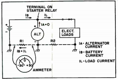
Fig. 3-8. Basic electrical system showing resistance in ground path circuit
discharge condition (engine stopped and electrical loads connected).
Ground Paths. Figure 3-8 indicates a simplified electrical diagram showing electrical loads connected to the system. This is a discharge condition in that the engine is stopped and there is no output from the alternator. Since the alternator remains connected to the system, it would appear that some drain would also result from the alternator. However, keep in mind that the alternator windings are connected to the positive terminal through diodes, and therefore, no reverse current can flow through the alternator. Under this condition, the alternator current 1A = 0. Applying Kirchhoff s Law which states the sum of the currents entering a junction is equal to the sum of the currents leaving the junction, we have the battery current 1B entering the terminal and the load current 1L leaving that junction. Since the alternator current is equal to zero, 1B = 1L., simply stated, the battery is supplying all of the required power to operate the load.
Let's discuss for a minute the theoretical versus actual conditions. We normally think of the negative terminals of the battery, alternator and loads as all being grounded together so that all negative terminals are at the same potential. However, in most cases, we are depending on the frame of the car as a ground return path, and since steel is a mediocre conductor, there is always some inherent resistance incorporated into all automobile electrical systems. This resistance is represented as R1 between the battery negative terminal and the alternator negative terminal and R2 between the alternator and the electrical loads. Applying Ohm's Law, the voltage drop across R1 would be:
E = (IB)(R1)
Granted, the resistance of R1 is small, in the neighborhood of 0.01 to 0.1 ohms, but the currents are very large-in the neighborhood of 10 to 30 amps (except during starts when it is much higher). Consequently, the voltage drop across R1 is a measurable quantity and can be used to indicate which way the current is flowing in the battery-alternator loop. This is shown on the meter in Fig. 3-8 as a discharge situation.
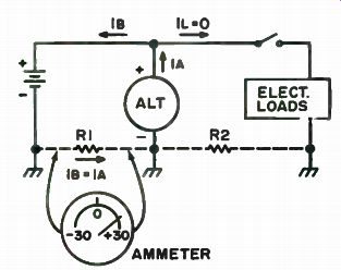
Fig. 3-9. Charging condition-engine running with electrical loads off.
Figure 3-9 is a diagram of a basic charge condition in which the engine is running and no loads are connected. Again, applying Kirchhoff s Law with 1L = 0 we have: 18 is equal to 1A, and the voltage drop across R1 is E = (1B) (R1), but is of the opposite polarity of the discharge condition in Fig. 3-8. As the battery becomes charged, the alternator current charging the battery gradually tapers off and so will the voltage drop across R1. We get a direct indication of the condition of the battery and we know exactly when it has reached full charge condition.
In Fig. 3-10 there is a diagram showing normal operation of the vehicle in which the engine is running and certain electrical loads are connected.
Under this situation, again applying Kirchhoff s Law, we have is and h, leaving the terminal and the alternator current, I A, entering the terminal.
Stated as an equation, 1A = is + 1L. This means that the alternator has to supply enough current to operate the electrical loads and charge the battery at the same time. Of course, as the battery becomes fully charged again, the battery current will gradually taper off, and the alternator will be operating mainly to supply cm- rent to the electrical loads connected to the system.
Ohm's Law Applied. It is apparent that there will be some voltage drop which can be measured across this ground path resistance, but just exactly how much will be measured and how can it be utilized in a charge indicator? Let's take for example, that the ground path has a resistance of only 0.01 ohms and that a typical alternator is capable of producing at least 30 amps. The voltage drop across the ground path of resistance would then be:
Therefore, E = IR = (30) (. 01)
E = 0.3 volts
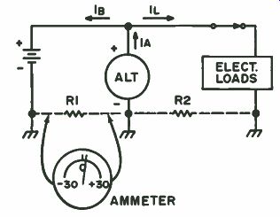
Fig. 3-10. Typical operating condition with battery charging current tapering
off.
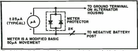
Fig. 3-11. Actual diagram for adding an ammeter to car electrical system-no
changes are required to existing wiring.
This voltage is easily measured and the instrument may be calibrated in terms of amps, that is, 0.1 volts would indicate a current of 10 amps.
If the normal charging rate is, for example, 10 amps, the voltage measured would be 0.1 volts. From this example, it is clearly evident that there is plenty of voltage available for a sensitive indicator and it can be used to advantage in a charge indicating instrument without adding additional shunt resistance into the electrical system. The next problem is to deter mine how and where to connect the meter in the circuit.
Basic Ammeter Circuit. Figure 3-11 shows the actual circuit used in a car with a 50 uA meter. This instrument, as with most instruments (even the very inexpensive tuning indicator instruments) can be converted to a zero center scale instrument so that the meter now has become a ±25 uA meter.
A meter protector circuit was installed across the terminals to limit the current during starting, and a 2k resistor was added into the circuit to allow for calibration of the meter.
As mentioned, the basic movement that was used was a 0-50 uA meter manufactured by Midland, Model No. 23-206. However, any meter may be used, possibly up to a 0-1 mA meter, depending on your own particular situation. You may want to use a VOM to check your particular ground path circuit under normal conditions to find out how sensitive a meter movement will be required in your particular case. After this has been determined and you have a meter available, the next step is to carefully remove the plastic cover on the meter. Then, after removing the two retaining screws of the dial, it must be carefully slipped out from under the pointer. Then, all that is necessary is to erase the lettering not required and to add in new lettering according to your own particular circumstances.
The next step is to convert the instrument to a zero center scale type instrument. This is easily accomplished by moving the zero adjustment until the pointer is at mid-scale. It is possible to do this on almost all instruments, including the little horizontal movements that are available through surplus outlets for $ 1.50. The quality of the instrument is governed only by your own particular needs. The final step is to replace the dial and plastic cover and install the protective diodes across the meter terminals along with the multiplier resistor used for calibration.
Installation Details. The next step involves installation in the car and connecting the meter leads to the proper points in the electrical system. It is best to use solid conductor wire of approximately 18. gauge, and if you can find Teflon-coated conductors, so much the better. Since the leads will be near hot parts of the engine, Teflon-insulated conductors are more resistant to heat and grease in this type environment. The two leads from the instrument circuit should be routed through any available opening in the fire wall and around to the alternator and negative terminal of the battery. One conductor is connected to the ground terminal on the alternator housing.
The other conductor is connected to the negative battery terminal right at the battery post. To check to see if you have the right polarity, leave the engine off and turn on some load such as headlights or press on the brake pedal. The instrument should swing from the zero center scale to the left indicating a discharge condition. If it swings the other way, the leads should be reversed. The next step is to get a rough calibration on the instrument.
Turn on headlights or some other load with a known amp rating and roughly calibrate the instrument based on this amount of load. If you have another ammeter, you can use it to check and calibrate your new instrument.
It is imperative to connect the ammeter circuit into ground path R1 between the battery negative terminal and the alternator ground terminal.
Otherwise, if by mistake it is connected between the battery negative terminal and ground near some of the electrical loads, it is easy to see from these basic diagrams that you would get roughly twice the indication on discharge which is the sum of the voltage drops across RI and R2 in a discharge condition. In a charge condition, the indication will be the difference between the voltage drops across R1 and R2 since the voltage drops are in opposite directions. This obviously will give you false indications and will be useless as far as determining the state of charge of your battery.
Conclusion and Results. You are probably wondering at this point as to whether or not it would have been easier to buy one of the commercially available ammeters for 6 to 10 dollars and not have the problem of converting another meter for use in this project. It is true it may have been easier, but the meter movement in commercial automotive instruments is not known for its quality and there are usually no means of calibrating the commercial instrument. Also, most commercially available instruments make use of an additional meter shunt into an electrical system of approximately 1/4 ohm.
Admittedly, this is not very much resistance to add into a circuit, but a quarter ohm at 20 amps could introduce an additional voltage drop into the automobile electrical system.
Simple Remote Ammeter Using a Bus-Bar Shunt
This is really a simplified method for cutting ammeter shunts. There are two things that will not happen. It will not be necessary to do any deep math, and the meter will not get pinned during the cutting process.
The voltage drop along a piece of wire is proportional to its length and the current through it. If a piece of heavy wire is hooked up as shown in Fig. 3-12, all of the sport is taken out of making meter shunts.
A power supply, ammeter, resistor and the bus bar that is about to become a shunt are all connected in series. Long thin flexible leads from the 0-5 mA meter may be used. After all, they are going to carry no more than 5 mA. The negative lead is tied to the power supply and bus minus. The power is turned on and adjusted to give the required current. This is shown on the standard VOMQ. The plus lead of the 5 mA meter is touched to the bus near the minus lead. There should be a small deflection seen on the meter. The lead is then slid along the wire until full scale deflection is obtained. That point on the wire is marked.
If a single range is all that is required, it only remains to solder the leads in place. The resistance change at the point of soldering will be small in comparison to the resistance of the meter. Therefore, the soldering operation will not upset the calibration.
Leave a little more bus at each end than is needed. If the shunt is rather long, then slide insulation over it before the final soldering. The wire may be wound on a convenient coil form in order to make it somewhat more compact.
If a 0-20 amp range is needed and there aren't more than 2 amps available, or the shack VOM doesn't have a high amp range, all is not lost.
Set things up as shown in Fig. 3-12 and adjust the power supply for, say, 2 amps. Then slide the plus lead for 20 divided by 2 or 1/10 of full scale. This ...
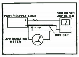
Fig. 3-12. Setup for shunting meter.
... will generally prove to be adequate calibration if the standard is reasonably close. Later, when the high current supply is finished and a higher range standard is available, it will take almost no effort to touch up the calibration.
If the shunt turns out to be 10" long for 500 mA, then halfway there, or 5 " up from the cold end will give a 1000 mA or 1 amp shunt.
A multi-range ammeter (Fig. 3-13) was constructed with this method in less time than it used to take to make a single shunt. Again, since the meter and its leads are carrying only 50 uA or 5 mA (whatever the basic movement is), then a cheap multi-position switch and light hook-up wire will do the job. Number 22 wire may be used for shunts up to about 1a.
This should get some of those low range mA meters out of the junk box and into circulation. And isn't that like getting a new meter for an old one? Although a 5 mA meter was used in this example, other meters may be used.
Find That Meter Resistance with This Simple Bridge
There comes a time in every hobbyist's life when he must seek that unknown meter resistance. Here's a simple solution to that age-old problem. The schematic is shown in Fig. 3-14. It's equivalent circuit is shown in Figs. 3-15A and 3-15B. In Fig. 3-15B, R2 is equal to R2, and R BP is the equivalent parallel resistance of branch 1 and branch 2. Neglecting RBP, the current through R2 would be 1.5 (E)/1500 (R) = 0.001 A or 1 mA, the full-scale reading of most meters. Thus, when we reinsert R BP, we know that the current is less than 1 mA. This keeps the current through each branch (Fig. 3-14) less than 1 mA, protecting both meters.
In Figs. 3-14 and 3-15A, when the resistance of branch 1 is equal to the resistance of branch 2, the currents through both are equal. Thus, you know that when the reading on the meter under test and the current reading on your meter are equal, the resistances of the two branches are equal.
The resistance of branch 1 is equal to the resistance of M1 (which must be known) plus R1, a potentiometer with a calibrated dial. If we select Rmi, then, when R1 is equal to Retest, the resistances of the branches are equal.
If the resistances of each branch are equal, the currents through them are equal.
To find the meter resistance, one must plug in the meter under test and rotate R1 until the currents through both meters are equal. Then we know that RI = Retest and its resistance can be read directly off the calibrated dial.
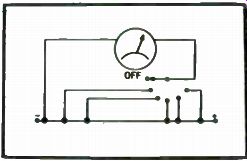
Fig. 3-13. Multi-range ammeter.
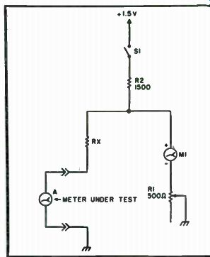
Fig. 3-14. Schematic.
The smaller the value of potentiometer R1, the more accurate is the measurement of Rm-test. This is because the dial can be calibrated in smaller units.
As an option, a more accurate circuit is shown in Fig. 3-16. A rotary switch can select different values of resistance to be added to R1. Thus, R1 can be made as small as you wish. Rm-test is now equal to R1 plus the switched-in resistance.
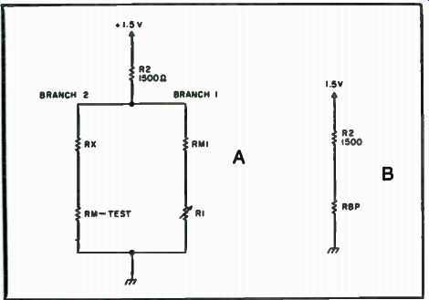
Fig. 3-15. Equivalent circuit.
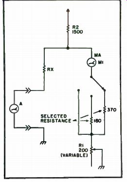
Fig. 3-16. More accurate circuit.
Let's say you wanted to measure a meter's resistance using only R1 (Fig. 3-14). If your dial was calibrated with 100 notches, the result would be 5 ohms per notch. If we use the circuit in Fig. 3-16, the potentiometer is only 200 ohms, leaving 2 ohms per notch on the same calibrated dial. Thus, we see how there is more accuracy in a circuit such as the one shown in Fig. 3-16.
Choose a meter with a low resistance. Also, if you prefer, you can use an ohmmeter to read the resistance of R1, thus saving yourself the trouble of finding a calibrated dial.
As you can see, the circuit is a flexible one and can be customized by the builder. All that is needed is a pen, paper and E = IR.
--
Next: Capacitance Meters