AMAZON multi-meters discounts --- AMAZON oscilloscope discounts
Build a Simple Capacitance Meter
A time-honored and very practical supplier of components for the latest experimenter's project continues to be the junk box. A well-stocked junk box not only reduces the cash outlay of a project, but also serves as a source of comfort and inspiration to the happy owner.
A major factor limiting the utility of these readily available goodies is the difficulty of identifying them properly. The number of books describing transistor checkers, IC probes and programs for identifying and checking ICs points not only to the popularity of the junk box source of supply, but also to the difficulty mentioned above.
Capacitors are a part of this problem. It seems that the original equipment manufacturers, the source of many of these components, delight in concealing the true value with an esoteric part number.
Cheer up! All is not lost. This is an unbelievably uncomplicated and cheap device that will go far toward blowing the cover of all those mysterious micas, discs and ceramics smirking at you from your hoard.
The Circuit. This little device is ridiculously simple and inexpensive. It consists of an oscillator and a rectifier, with a meter to indicate the value of the rectified current. Let's refer to Fig. 4-1 and be a bit more specific. U1A and U1B are two NAND gates of a CMOS quad two-input NAND gate. You can get one for $ 0.29 if you don't have one. These two gates are cascaded, biased in the linear mode by the resistor network and caused to oscillate by capacitive feedback around the two gates. The output is a square wave which is buffered by the third gate U1C to insure an output of constant amplitude. We apply the output of the buffer to the diode rectifier through our unknown capacitor. If the unknown capacitor is small (has high reactance) in comparison with the frequency of the oscillator, it will pass a small pulse on each cycle which will be rectified by the diodes. The meter will read the sum, or integral, of these pulses. The larger the value of the capacitor, the larger the pulses, the greater the sum and the higher the meter reading. Simple, isn't it? This is a basic counter circuit. With a given value of capacitor, if the oscillator frequency is increased, there will be more pulses per second, thus a higher integrated meter reading. This forms the basis for a very simple and useful counter which is linear over quite a few octaves. We are simply turning the circuit around to measure capacity instead of frequency.
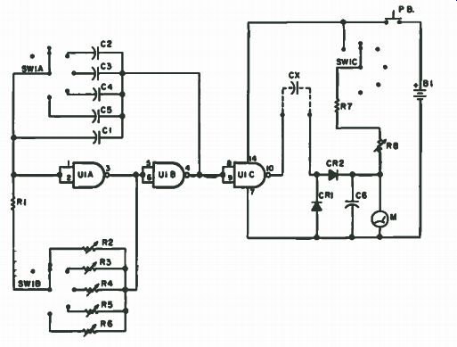
Fig. 4-1. Schematic.
Table 4-1. Values for a 1 mA Meter Movement.
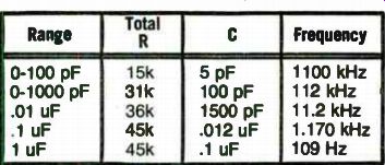
Circuit Details. The circuit was set up to use a 1 mA meter movement. The values shown in Table 4-1 list the oscillator frequency, capacitor and resistor values for a 1 mA meter movement. There are five ranges arranged as decades. The lowest range is 0-100 pF, the next 0-1000 pF, etc. Each range is linear, so it is quite possible to read a 5 pF capacitor on the lowest range. The highest range then reads full scale on a 1 uF capacitor.
It would be inadvisable to use a meter with less sensitivity than 1 mA if the 0-100 pF range is desired. Note that with the 1 mA meter, the oscillator is running at a frequency slightly greater that 1 MHz. This is approaching the top frequency for this chip in this circuit. Conversely, if a sensitive meter such as 50 uA is available for this use, it should be desensitized to some extent if the 1 uF range is desired. With a 1 mA meter, the oscillator frequency is only 109 Hz on the 1 uF range. The 50 uA meter would require this frequency to be reduced to 5 or 6 Hz for this range, which would require awkward capacitor values in the oscillator and an excessively large smoothing capacitor to provide a steady reading on the meter. Approximate oscillator frequencies for meter movements from 50 uA to 1 mA may be interpolated from Table 4-1.
Construction. Table 4-2 lists the necessary parts. The instrument was housed in a discarded multimeter cabinet. One of the many miniboxes available would be entirely satisfactory. The circuit was constructed on a piece of perforated board which was mounted on the meter studs. Trimpots were used to set the battery check and individual capacitance ranges. The 5 pF capacitor for the 0-100 pF range was soldered directly across the IC socket and is in the circuit at all times. A five-position two-pole rotary switch is required. We added a battery check position on the switch, which required a third pole and sixth position on the switch. A push-button for the battery check function would do as well. The two leads to the binding posts of the unknown capacitor should be routed in the clear and not twisted together for neatness; their mutual capacity will show on the low range! Calibration and Operation. When the unit is completed, it should work just fine, but it probably will not. First check to make sure the gates are oscillating. Since they are biased in the linear mode, all gates and outputs should be at about half the battery voltage. If they are at zero of full voltage, they cannot oscillate. If they are at about half-voltage, they just about have to oscillate if the circuit is wired correctly. When oscillation has been proven, the diode circuit will rectify and indicate on the meter, unless a diode is reversed or there are other wiring errors. This is not a cranky circuit.
After you find the wiring error and get the thing working, the rest is a snap. With a fresh battery, set the battery check trimpot for a full-scale reading on the check position of the switch. In spite of the junk box complex, most of us have some capacitors that are marked. Calibration was begun on the most sensitive range. Select three or four 100 pF capacitors and set the trimpot for a full-scale reading. Micas are usually pretty close and very little discrepancy will be observed.
Also, check some smaller values, such as 50 pF, 10 pF and 5 pF to make sure that the scale is linear and all is well. Using the 100 pF capacitor, decade up to the next range and set the trimpot for 10% full scale. Now try a 1000 pF. It should read pretty close to full scale.
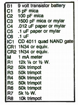
Table 4-2. Parts List.
---------------
B1 9 volt transistor battery C1 5 pF mica C2 100 pF mica C3 1500 pF mica or mylar C4 .012 uF paper or mylar C5 .1 uF paper or mylar C6 .1 uF IC1 CD 4011 quad NAND gate CR1 1N34 or equiv.
CR2 1N34 or equiv.
M 1 mA meter R1 12k 1/4 or 1/2 W. R2 50k trimpot R3 50k trimpot R4 50k trimpot R5 50k trimpot R6 50k trimpot R7 5k 1/2 W. R8 10k trimpot
----------------
In short, if you have a selection of known capacitors, you will be able to set each range without difficulty. Note that once you have proven the scale is linear, you can use intermediate values to calibrate. A . 5 uF capacitor can be used to set the 1 uF range, for example. It is best to try three or four different capacitors of different types for each range. You will find that consistency can be achieved and the calibration is sufficiently accurate for all practical purposes. If you are a nitpicker and have a friend with a good bridge, you can achieve good accuracy.
Operation is very simple. Place the capacitor across the binding posts and depress the button. Read the capacity on the meter. If the meter tries to go beyond full scale, go to a higher range. If the meter reads less than 10% full scale, turn to a lower range. That's all there is to it! The circuit is self-limiting; the meter may bang over full scale if the capacitor is too large for the range selected, but the current supplied will not burn out the meter.
No current is drawn from the battery unless you depress the push-button, so the battery cannot be run down because you forgot to turn the thing off.
Current drain while checking is less than 5mA. Build This Digital Capacity Meter One of the common problems any constructor faces is determining the exact capacity of a capacitor from his junk box or for use in af filters, etc.
Small (and cheap) RLC bridges are not accurate enough and if, for example, you try to measure 100 mixed values of capacitors from a surplus pack, you may well run out of patience. Furthermore, in the age of integrated circuits and frequency counters, everybody is getting lazy. Well, here is an instrument which eliminates all these troubles, presents the value of capacity instantly in digital form, is highly accurate and is fairly simple to construct.
First, some information about the C-meter:
• It measures capacitors from 1 pF to 1 uF in two ranges-9999 pF and 999.9 nF.
• Display is four digits in these ranges, with leading zero suppression and overflow indicator.
• Accuracy is better than ± 1% of full range ± 1 digit for higher values of capacitance in both ranges; for lower values of capacitance it is still very good (i.e., it is possible to determine if the measured capacity is 1 or 2 pF). This accuracy is of course in relation to the standard used for calibration of the C-meter and applies only to capacitors with a good Q.
• No warm-up period is required. It measures immediately after switching on, with full accuracy.
• Operation is extremely simple, with only two controls: zero adjustment and range switch.
• With the exception of a power supply, the whole unit fits on two small printed circuit boards.
• The price of the complete unit should be around $50, depending on how familiar you are with cheap sources of TTL integrated circuits.
Maybe most of them are in your junk box.
The basic principle is very simple and well known; the only difference is how it has been used. There is a similar unit, but it measures only higher values of capacitance and uses different devices.
Figure 4-2 shows the block diagram of the C-meter. The heart of the unit is the monostable multivibrator (MMV), which produces gating pulses.
The length of these pulses is directly proportional to the value of capacitor Cx. Consider the practical limits of your MMV integrated circuit, the crystal oscillator and the frequency counter. The MMV integrated circuit used in this case is number SN74121. Using only Cx and no CF, with the highest permissible value of the timing resistor, will result in a pulse length of about 25 usec. The crystal oscillator frequency must then be 40 MHz in order to obtain " 1000" on the display. But, if due to the long leads to the terminals for Cx, hum, etc., the display is not stable, especially for values of Cx under 100 pF, start with a value for Ce of 1000 pF. This should cure the problem. With no Cx on the terminals there will be " 1000" on the display. Instead of resetting to "0000," reset the counter to " 9000;" then with no Cx it will count to " 10000," but the first digit will not be displayed and the resultant display is "0000." Similarly, for higher range, the counter can be reset to "9990." Reset circuits are then a bit more complicated and the overflow indicator must be a two stage counter, but this is not a serious complication.
Capacitance ratio between range 1 and 2 is 1:100. To obtain a correct reading on range 2, the frequency of 40 MHz (for range 1) must be divided by 100, resulting in a frequency of 400 kHz.
The last part of the C-meter is the timing circuit. It generates trigger pulses for the MMV, strobe pulses for latches and reset pulses for counters.
The last ones are distributed with the help of a few TTL gates.
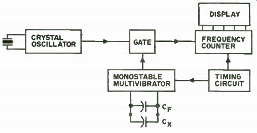
Fig. 4-2. Block diagram.
Flicking of the least significant digit is not suppressed for two reasons: to simplify construction and to enable recognition of differences between, say, 17.0 and 17.5 pF. In the latter case, the display would change from 17 to 18. Using cheap Minitrons for display determines the frequency of the timing circuit; it must be low enough to read both values comfortably, e.g., 17 and 18. After a few tests leave it at about 2 Hz. The timing oscillator is then running at 20 Hz and is divided by 10 with the SN7490. Pulse " 4" is used for triggering the MMV, "6" is used as strobe pulse for latches and "8" is used for reset pulses. This system works very well and leaves about 100 ms between trigger and strobe. With 1 uF and 40k ohm, the SN74121 generates about 25 ms pulses, so that it is well within the above 100 ms. Any other combination of the outputs from the SN7490 is, of course, possible (Fig.
4-3). The instrument can also be divided into two parts:
• Crystal oscillator, MMV, timing circuits and gate.
• Frequency counter and display with overflow indicator.
This arrangement reduces the size of the printed circuit boards which are mounted in parallel and interconnected by means of a few wires. Both parts can be tested separately before final assembly of the whole C-meter.
Frequency Counter and Display with Overflow Indicator. This unit is mounted on a single-side printed circuit board 110 by 80 mm. Using a single-sided printed circuit board for such a complex circuit results in a few jumpers being necessary. However, the use of double-sided printed circuit board would not be fully justified-it would be much more difficult and expensive.
This unit is basically a four-stage frequency counter with overflow indicator,' which reacts only to every second pulse from the last decimal counter. Decade counters used are SN7490, with the exception of the first one, which must handle frequencies around 40 MHz. An SN74196 is used here instead, as it can handle frequencies over 50 MHz. Latches SN7475 and BCD-to- seven-segment decoders SN7447A are used to drive 7-segment incandescent displays (Minitrons) of a cheap foreign make, type 3015-F. If any other type of 7-segment display is used, you must check to see if the pin arrangement is the same. If not, the printed circuit board must, of course, be modified accordingly. The overflow indicator uses an SN7473, one surplus plastic switching transistor and an LED (TIL209 or similar). Use IC sockets for the Minitrons only (MOLEX type); all the other integrated circuits are soldered directly into the printed circuit board. With surplus integrated circuits this is a bit risky. The decision is yours.
There are four resets for the counters, as well as one for the overflow indicator and strobe for the latches. Two wires are for switching the decimal point of the second Minitron for the higher range.
Oscillator, Gate, MMV and Timing Circuits. One of the most successful of harmonic oscillators is shown in Fig. 4-4. It is reasonably stable and the output voltage is high enough to drive a buffer stage, which drives high speed gate IC14A (SN74H00). Crystal X is a harmonic type (3rd or 5th harmonic) and any frequency between 35 and 45 MHz is suitable. Coil Li has 10 turns of 28 SWG enameled wire on a 5 mm diameter with a tuning slug.

Fig. 4-3. Note: Cut off pin 4 of ICs 2 and 3 (SN7490).
Capacitor Co tunes with Li to the harmonic frequency of the crystal X. The coupling coil is 2 turns of insulated wire (24 SWG) over the "cold" end of L1.
The buffer stage Q3 must safely drive the buffer gate IC14A. The easiest way to check if IC14A is driven enough is to measure the voltage with an rf diode voltmeter at pin 11 of IC14. If the rf voltage is low or unstable, change the value of the base resistor of transistor Q3 or the transistor itself. Unstable or low rf voltages (e.g., under 2v) will result in unstable or no display of the measured value of capacity. So get it to work one hundred percent. This is probably the only difficult part of the whole instrument.
The rf output from IC14A is fed into another gate IC ( 14B) and divided by 100 (IC15 and IC16). Range switch SIB blocks IC16 for range 1 via IC20E, so that at the output (pin 11) of IC16 there is logical " 1." At the output of IC14C (pin 3) is a 40 MHz signal. If the range switch S1B is in position 2, gate IC14B is blocked, the output (pin 8) is logical "1," IC15 and IC16 divide the 40 MHz by 100 and the 400 kHz output (pin 11 of IC16) goes via IC14C to pin 4 of the gate IC14D. One half of IC17 (dual Schmitt trigger) works as an oscillator; a 47 uF 10 V solid tantalum capacitor and a 470 ohm resistor make up the timing circuit for approximately 20 Hz. This frequency is fed into IC18 (an SN7490 decade counter). The B, C and D outputs of IC18 are used to produce trigger, strobe and reset pulses. Trigger pulse "4" from pin 8 of IC18 is reshaped in the second half of IC17 and fed into IC21 (the SN74121 MMV), which produces a pulse with length directly proportional to the value of capacitor Cx (+C F). This pulse (at pin 6 of IC21) is used to enable gate IC14D. The output from IC14D (pin 6) goes to the counter input.
Strobe impulse "6" is formed by the B and C outputs from IC18 (the decade counter) in the gate IC19B (SN7400). The output is a negative impulse and, as the SN7475 latches require positive pulses, it is inverted in one of the hex inverters (IC20B) of SN7404.
Reset 1 and 4 pulses are common for both ranges. The D output from IC18 goes via IC19A to Reset 1 (negative pulse). Reset 2 must be a positive pulse- thus, Reset 1 is inverted in IC20A. For range 1, the Reset 3 pulse must be positive. With S1B in position 1, gate IC19C is open but the output pulse is negative--it is therefore inverted in IC20C. The Reset 2 output is logical "0", as IC19D is blocked.
For range 2, the Reset 2 pulse must be positive. Switch SIB is in position 2 and gate IC19D is open, while IC19C is blocked and the Reset 3 output is logical "0." Power Supply. The last part of the C-meter is the power supply. It is very simple, thanks to IC22 (MC7805CP). This integrated circuit has built-in overcurrent and thermal protection and is a very good buy for the money (Fig. 4-5). The output voltage should be very close to +5v (according to the specifications ±0.2v, but there are a few worse than ±0.1v). It is rated for 750 mA minimum (short circuit current limit) and this value just suits our requirement (about 700 mA with display "88881. The typical input-output voltage differential of the MC7805CP is 2v, but to be on the safe side use 8v AC. With a large smoothing capacitor the input voltage is over 9v DC. Do not try to go under this value (at nominal mains voltage); otherwise, when the mains voltage drops, you are in trouble.
A small capacitor across the output improves transient response. The connection between the 5000 uF and the input of IC22 should be as short as possible. Use heavy wires-they eliminate voltage drops and improve stability.
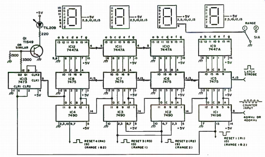
Fig. 4-4. Schematic
To suppress spikes from TTL integrated circuits, it is essential to connect a few capacitors of 0.1 uF and 50 or 100 uF tantalum at intervals on both printed circuit boards. The 0.1 uF capacitors are Siemens, type B32540-A3104-J metallized polyester. Their advantage is very low induc tance, but even the ceramic disc capacitors will do the job. Be careful about the polarity of tantalum electrolytics.
By the way-the IC22 regulator needs a heat sink to dissipate about 3w. A small piece ( 100 x 100 mm) of 2 mm (approximately 14 gauge) aluminum is more than adequate; if a metal box is used, just mount the regulator on the rear side of the box.
Construction. Mechanical construction is probably the weakest point of most of the equipment. Not everybody has a well-equipped mechanical workshop.
But C-meters can be built in your home. One can be built into a homemade cabinet. The basic dimensions and the general idea are shown in Fig. 4-6.
U-shaped parts a and d can be bent in a big vise. The other parts are very simple. Aluminum (2mm, 14 gauge) can be used for all parts of the cabinet. Start with parts a, b, c and d, and then measure the inside dimensions and cut front and back panels e and! accordingly.
The front and back panels are held 94 mm (inside dimension) apart by means of four 4 BA screws 102 mm long. This sub-assembly is then inserted between the two U-shaped parts a and d. Parts b and c prevent the front and back panels from moving and hold parts a and d together.
After drilling all necessary holes into the front and back panels, clean the front panel and mark all holes with a pencil on a piece of thick white paper which does not change its dimensions with moisture. A white plastic sheet would be even more suitable. Cut off all the marked holes with a sharp knife.
Use transfer letters (Letraset or similar) for descriptions of the functions on the panel. Then cut a 1.5 mm thick piece of clear Perspex (Plexiglas) and drill all holes with the exception of the ones for display LEDs and overrange LED. Cut a piece of red Perspex (3 mm thick) which will fit exactly into the hole for the LED display in the front metal panel e.
Perspex is supplied with paper sheets glued on both sides. Do not remove these; mark all the holes and outside lines with a pencil and then make cuts with a sharp edge along the outside lines, about 0.2 mm deep. Use the sharp edge of a small chisel (along a steel ruler) with success. Do only one cut at a time. Break both ends of the cut slightly with your fingers. Lay the Perspex over the edge of the bench and break carefully. Try this procedure a few times on Perspex off-cuts. The operation is not difficult but does require a bit of practice.
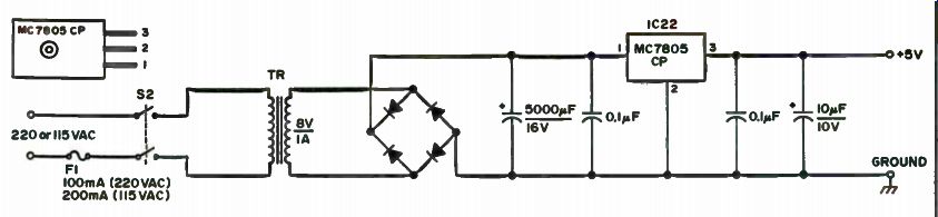
Fig. 4-5. Note: MC7805CP mounted on a heat sink.
Drilling of holes in Perspex is also a little difficult. The best method is to use a drill press with a maximum of 500 rpm. A bit of practice on a piece of off-cut is not a waste of time. Only after drilling all holes, cutting the right dimensions and smoothing the edge with sandpaper should you remove both paper covers and wash the Perspex with soap and water. A front panel made this way looks professional and is really worth the effort.
The printed circuit board with LEDs is fitted parallel to the front panel by means of four screws with countersink heads so that they are covered with the paper and not visible.
Both terminals of Cx must be made from a good insulator or fitted on a piece of Teflon (PTFE). Perspex tends to absorb moisture from air-a bad insulator will cause erratic readings.
The transformer, IC22 and the 5000 uF electrolytic capacitor are fitted onto the rear panel. Use a small transformer (or increase the depth of the box), so that it does not interfere with the printed circuit boards.
For the second construction of the instrument, you could use a ready to-use plastic cabinet with a metal front panel. This is the lazy man's construction and it is, of course, less mechanically difficult. Due to the bigger size of the box, it does not need the cooling holes that proved to be necessary in the previous construction. The construction of the front panel is the same as in the previous case.
Fiberglass printed circuit boards should be well washed with soap and water after etching, rinsed, dried and polished with steel wool. Then spray both boards with soldering varnish and let them dry in the oven. This protection is very important. Otherwise, after a few years you might be surprised to find that your C-meter does not work. Only after this procedure can you start drilling the holes into the printed circuit boards. Holes 0.8 mm in diameter are adequate for all components and wires, except the five thick interconnecting wires for the ground and +5v.
Soldering should be done with a small soldering iron-preferably temperature controlled. Start with the jumpers; a few long ones should be insulated wire, while the others can be bare wire 0.6 to 0.8 mm in diameter.
Then solder the components and integrated circuits. Be sure that all integrated circuits are positioned the right way. Do not forget to cut off pin 4 of ICs 2 and 3 (SN7490), before soldering them onto the printed circuit board.
You can test each printed circuit board separately. Use your laboratory 5v power supply or the one for the C-meter. The current consumption of the frequency counter part with display is approximately 500mA; of the second part, around 200 mA. To test the counter sub-unit, Resets 2, 3 and 4 must be grounded and Reset 1 must be connected to +5v. Then connect a square wave generator to the counter input. A circuit of the timing oscillator IC17 (SN7413) can be used (use pin 6 as output). The display will start counting at a random number and will continue to over 9999 and 0000 again.
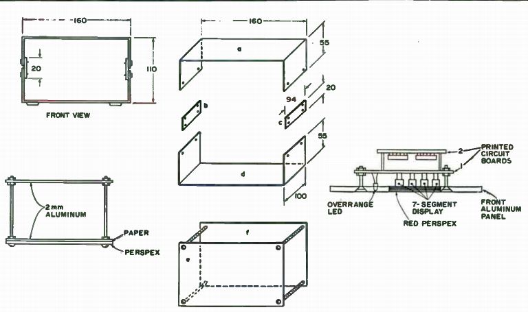
Fig. 4-6. A C-meter can be built into a homemade cabinet.
The second part of the C-meter can be checked with a frequency counter (output from IC14D pin 6). You must, of course, simulate the function of the range switch S1B. Output frequencies (at pin 3 of IC14C) must be exactly at the ratio of 1:100. The latch and reset pulses can be checked with an oscilloscope or, preferably, with a logic probe.
Alignment. If both parts of the instrument work satisfactorily, solder the two printed circuit boards together. Five thick wires should be soldered onto the counter board. To make this operation easier, use differently colored insulation on the interconnecting wires. The same applies to the range switch wiring.
Check the output voltage of the power supply. If possible, load it with a 6.8 ohm resistor to check if the, output voltage is stable. This checking is important, as any voltage over 5.25v can damage some integrated circuits.
Then check the current consumption of the whole unit. It should be under 0.75 A. If everything is alright, you can start with alignment.
Set "Zero Adj" (ZA) and "Zero Preadj" (ZP) to the center positions.
Solder a few (two or three) capacitors, which are stable with temperature, across the Cx terminals (inside the cabinet). Used plastic molded silver mica and polystyrene. In parallel, solder a small mica trimming capacitor (20 to 50 pF). The total value of all of them should be about 980 pF. They form capacitor C F. The difficult problem here is to get hold of a very accurate capacitor whose value is between 5000 and 10,000 pF. The future accuracy of the instrument depends upon the accuracy of this capacitor. So have a good look around for it. Note that either input terminal is grounded. Of course, the one marked "+" is not very sensitive to hum, etc.
With no capacitor Cx you should be able to adjust the instrument to show zero on the display, with the values of resistors 12k and 22k next to ZA and ZP. But if you used a crystal of a frequency lower than 40 MHz, these resistors will be slightly higher in value (say 33 and 10k) and vice versa. By the way-they must again (like ZA, ZP and C F) have a very low temperature coefficient. It is best to start with ordinary resistors and replace them, after finding the right values, with high stability ones.
Anyway, adjust zero with ZP and then connect the precise capacitor Cx. If it reads low, adjust capacitor C F to the lower value. Remove Cx and adjust zero with ZP (changing 12k and 22k if necessary). Try it again with Cx and adjust C F. Remove Cx and adjust the zero with ZP. (Basically, when the display shows a low value, you must lower the value of Cr, and vice versa.) Continue in this way until the display shows zero without Cx and the right value with Cx. During this procedure ZA is adjusted to the middle position.
And that's it. Now you can take, say, 20 mica or polystyrene capacitors 200 to 500 pF, measure each one of them, mark the value and add them one after another in parallel on the terminals of Cx. The difference in total readings should at any point be not more than ±2 digits. If more, then the insulation between terminals 10 and 11 of IC21 (MMV) or between terminals Cx is bad and must be improved.
This procedure of adding measured capacitors in parallel, demonstrated the excellent linearity of the SN74121 MMV. It is really amazing how these small plastic 14- and 16-legged spiders perform.
The higher range 2 does not need any alignment, as it is automatically alright when the lower range 1 is adjusted.
Conclusion. Inside the cabinet, the integrated circuits, display, IC22, etc., dissipate over 5w. Certain crystals tend to be unstable at the high temperature which can develop when the instrument is switched on for a long period of time. In this case, drill a lot of small holes in the top and bottom of the cabinet in order to allow air to circulate along the printed circuit boards.
Take advantage of this instrument-it measures with practically full accuracy within a second of being switched on. Just adjust the zero by means of ZA (with range switch in position "pF," even when measuring in the nF range) and connect the capacitor across the terminals Cx. If you measure a lot of capacitors, check the zero from time to time, as it drifts slightly with temperature.
The overrange flickers when you exceed the range. This is much better than a steady signal.
If you are measuring solid tantalum capacitors, connect them with the correct polarity at terminals Cx. The polarizing voltage across these terminals is about 3v DC. This low voltage limits accurate measurement to only low voltage electrolytic capacitors.
If the reading is not stable and changes by more than ± 1 die, then there is something wrong with the capacitor and you would do best to throw it away.
How Many pF Is That Capacitor, Really?
Tucked away in our junk box someplace, most of us have jars, boxes, paper bags or whatever of surplus capacitors- capacitors that are perfectly usable but not particularly useful because we can't decipher the color code or numbering system that designates their value. Many of us have also had occasions when we wished to twist up a "gimmick," or check the value of an unmarked air-variable or determine the exact value of a ceramic disc before we install it in a particularly critical circuit. The more sophisticated tinkers may recall a time when they wanted to measure the stray capacitance between the leads in a wire bundle or between the foils on a printed circuit board. If any of these situations sound familiar, read on, because here is a project to help you out of all those dilemmas. When completed, it will provide you with the capability to measure any value of capacitance between 0 pF and 1 uF by merely pushing a button and reading a meter. Not only that, the cost is reasonable, construction is quick and easy and the parts are available from your nearest Radio Shack or mail-order parts supplier if they aren't already in your junk box.
The circuit is an adaptation of an old principle which, simply stated, says that the AC current flow through a capacitor is dependent upon the voltage applied, the frequency of the waveforms and the value of the capacitance. In this case, use of a square wave allows the capacitor to charge to its full potential and permits measurement of current flow as a linear function of capacitance.
In operation, depressing the read button applies the regulated 15-volt output of the LM78L15 to the LM566 phase locked loop voltage controlled oscillator (VCO). Regulating the Vcc input to the VCO insures that the calibration of the capacitance meter will be stable as long as the battery voltage remains above approximately 16 volts. The frequency at which the VCO oscillates is determined by selection of the proper RC combination (R1/C1, R2/C2, etc.) with the rotary switch. The square wave output from pin 3 is fed directly to the unknown capacitor whose value determines the current flow and subsequent meter reading. Rectification and filtering are provided by diodes D1 and D2 and the 30 uF electrolytic capacitor. The switch selected RC combinations provide six linear scales: 0-10 pF, 10-100 pF, 100-1000 pF, 1000 pF- 0.01 uF, 0.01-.1 uF, and 1.1 uF. Accuracy, dependent primarily upon the tolerance of the meter and the capacitors used for calibration is approximately ±5 percent. If a high quality meter is used and 1 percent tolerance capacitors are available for calibration, an accuracy ±2 percent-or better is possible.
For the most part, component selection is noncritical. The values of frequency-determining capacitors C1 through C6 may deviate from those specified by as much as 50 percent, but should be as stable as you can find to insure that the accuracy of the instrument is maintained under changing environmental conditions. The prototype used an aluminum electrolytic for C6 and ceramic discs for the remainder. After a night in the car at 15°F, the . 1-1 uF scale read 10 percent low and the other scales were in error to some lesser degree until the instrument warmed up to room temperature. Diodes D1 and D2 can be either silicon or germanium, and the value of the 30 uF electrolytic can vary from 22 to 50 uF. The higher value will provide better filtering action at the low operating frequency of the 0.1-1 uF range, but slows the meter response when the circuit is activated. For R1 through R6, the fancier multiturn trimpots are nice and ease calibration, but the cheaper single-turn variety are more than adequate and are what the circuit board was designed for. If you're going to splurge anywhere, capacitors C1 through C6 and the meter movement are where quality counts most in this project.
Construction is accomplished by referring to Figs. 4-7 through 4-10 and Table 4-3. Begin by drilling and lettering the front panel. For professional looking results, the panel can be roughed with a stainless steel pad, or, if you prefer, sprayed with the background color of your choice. Lettering is most easily accomplished using "Dri-Transfer" letters available from Radio Shack, stationery stores and other sources. For durability, the lettering should be sprayed with a dear protective coating such as Krylon. After lettering, install the meter, binding posts and push-button switch, and then put the case aside for the moment.
Next install the remaining components, including the rotary switch, on the circuit board. R1 through R6 and C1 through C6 mount on the foil side, ...
-----------------------
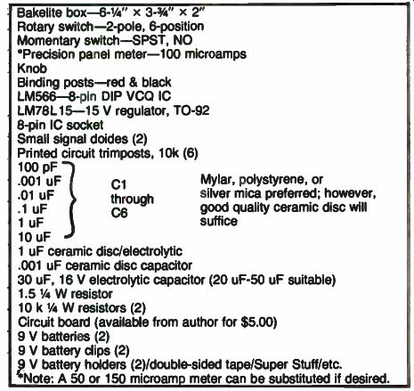
Table 4-3. Parts List.
Bakelite box-6-1/4 " x 3-3/4 " x 2" Rotary switch-2-pole, 6-position Momentary switch-SPST, NO
*Precision panel meter-100 microamps Knob Binding posts-red & black LM566-8-pin DIP VCQ IC LM78L15-15 V regulator, TO-92 8-pin IC socket Small signal diodes (2)
Printed circuit trimpots, 10k (6)
100 pF
.001 uF I C1 Mylar, polystyrene, or
.01 uF through silver mica preferred; however,
.1 uF I C6 good quality ceramic disc will 1 uF suffice 10 uF 1 uF ceramic disc/electrolytic
.001 uF ceramic disc capacitor 30 uF, 16 V electrolytic capacitor (20 uF-50 uF suitable)
1.5 1/4 W resistor 10 k 1/4 W resistors (2)
Circuit board (available from author for $5.00) 9 V batteries (2)
9 V battery clips (2)
9 V battery holders (2)/double-sided tape/Super Stuff/etc.
*Note: A 50 or 150 microamp meter can be substituted if desired.
--------------------
... the remaining components on the reverse. The circuit board is supported by the switches and the leads from the binding posts. Solder a short length of solid conductor (a clipped-off resistor lead will do fine) directly to the tip of the screw end of each five-way binding post. Fit the board into position over the binding posts and push-button switch terminals and install the nut on the shaft of the rotary switch. Solder the leads from the binding posts and lugs from the push-button switch to the board. Connect the meter leads to the points indicated and connect and install the batteries using double-sided tape or "Super Stuff' to hold them in position next to the meter.
After admiring your handiwork, you're ready for calibration. Use the most accurate capacitors available and begin with the x 1 scale (0-10 pF). Connect the calibration capacitor to the terninals and adjust R1 for a meter reading that matches its value. When you have completed this procedure for the other five scales, install the completed instrument in the case and grab a handful of those previously unusable capacitors out of your junk box.
When measuring values of less than 10 pF, stray capacitance can be a problem, so connect the capacitor leads directly to the terminals if possible.
If not, plug in a set of extension leads with banana plugs on one end and alligator clips on the other. Position them as they will be when you are making the measurement and check the stray capacitance. Subtract this reading from the indicated value of the unknown capacitor to obtain the ...
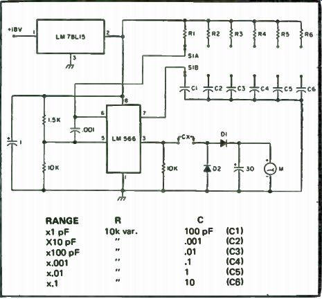
Fig. 4-7. Note: All capacitance in microfarads unless otherwise annotated.
... actual value. If extension leads of more than 2" are required, the same procedure should also be used on the x10 ( 10-100 pF) scale.
A Digital Capacity Meter Simple Construction Project
There are many means of taking the measure of a capacitor. For the range of capacitors that the instrument to be described can handle (approximately one microfarad to 99,900 microfarads), the best method to refer to is time versus voltage. Mother Nature and science reached a detente relating the charge or discharge to reach some specific limit. The charge limit reaches 63 percent of the applied voltage in RC seconds, where R is in megohms and C is in microfarads. Thus, if you were to apply exactly 10 volts to a capacitor which you made sure was totally discharged, through a resistor of 1 megohm, and you monitored the voltage rise across the capacitor with a voltmeter that did not load down the circuit, you could use a stopwatch to time the number of seconds it took for the voltage to hit 63 percent of 10 volts, or 6.3 volts. It is easy to see that a 1-microfarad capacitor would time out at 1 second and that a 100-microfarad condenser would time out at 100 seconds.
You could work the same general method using the discharge curve, but your point of measurement would be when the voltage had fallen 37 percent from a fully charged capacitor. Herein lies the rub, for it is much harder
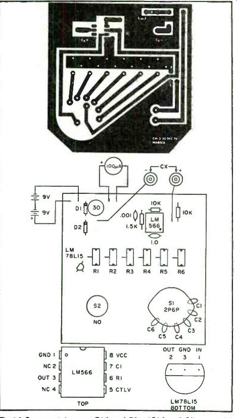
Fig. 4-8. Component placement. R1 through R6 and C1 through C6 mount on foil
side of board, all other components on reverse.
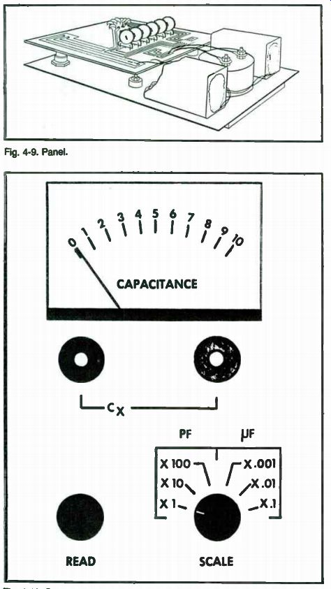
Fig. 4-9. Panel.

Fig. 4-10. Suggested front panel layout.
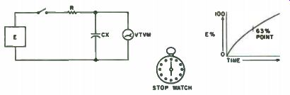
Fig. 4-11. Basic concept of capacitor measurement using time versus charging
voltage rise.
to tell when a capacitor is fully charged than fully discharged. It takes about six RC time constants for a capacitor to charge to about 99 percent of final full charge, so you would have time to read the paper if the capacitor under discussion was a 92, 000-microfarad unit from your favorite computer.
Figures 4-11 and 4-12 diagrams the basics required to translate the time-versus-voltage method of capacitor measurement into terms of electronic hardware.
Figure 4-13 is the schematic diagram of the actual unit, which works as follows: Note the "Function" switch S- 1-1a, 1-b, 1-c (three pole, double throw). In the OFF position, this switch performs the following three tasks:
• It provides a short across the capacitor connected to the test leads so that you start out with a fully discharged capacitor
• It blocks the flow of 60 Hz timing pulses to the counting system, which consists of a squaring circuit followed by a divide-by-six counter which produces 10-Hertz pulses.
• It makes the reset terminals of the three 7490 decade counters HIGH, which is the condition required to make the three-digit display show all zeros prior to making a count.
In the Test position of this switch, the following conditions prevail:
• The short is removed from the capacitor under test and it is connected to the measuring circuitry which starts out basically with the range switch S-2 (one-pole, four-positions) and the 741 op amp used as a comparator.
• It connects the 60 Hz timing waveform to the sine wave squaring circuit which uses two sections of the 7408 and gate package.
• It puts a ground on the 7490 reset line so that the counters will now be enabled to count.
Switch S-2 is the range switch, giving scaling factors of 1, 10, 100 and 1,000. The zener-regulated nine volts positive is applied to the capacitor under test through one of these range resistors. Notice that the inverting input of the op amp is connected to a positive voltage through a voltage divider. Under conditions where the positive voltage to this input is greater...
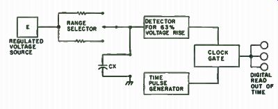
Fig. 4-12. Basic translation into electronic hardware.
...in magnitude than the positive voltage applied to the noninverting input, the output of the op amp (pin 6) is highly negative. When the charging voltage of the capacitor under test reaches and just slightly exceeds the reference voltage on the inverting input, then pin 6 (output) goes highly positive.
In this fashion, by changing output polarity, the comparator gives a fixed point in time when the charging voltage just exceeds the reference voltage applied to the inverting input of the op amp.
Now all you have to do is provide a means of automatically starting a "clock" coincident with the start of the charging cycle and use the flip-flop of the comparator to stop the clock. Then the capacity of the unit under test is merely the multiplier of the range switch times the number of full and fractional seconds shown on the three-digit readout.
Tackling the bits and pieces of how this all happens, consider the output swing of pin 6 of the comparator. It goes from approximately minus 8 to plus 8 volts in the course of normal operation. The function of Q1 (2N3904) is to convert this voltage swing to standard voltage levels acceptable to the TTL logic blocks used in the unit. In addition to this interfacing function, the output from the collector is inverted in polarity, which you will see is needed to fit the rest of the circuit functions.
Since the timing chain starts in the power supplies, just a word should be said about that here. The 5-volt supply is run of the mill with a 1-amp capacity regulated by an LM309K. You can lash up any kind of a plus and minus 9-volt supply you care to for the op amp, but it must be zener regulated, at the least. From the transformer for this split supply, you need to provide a source of 60 Hz voltage from a voltage divider ( 1.3 to 1.5 volts AC), the only proviso being that the leg of the divider to ground should be about 1500 ohms or less. This is so the squaring circuit which is next in line sees a reasonably low impedance.
The low-voltage AC goes to the two sections of the 7408 through a diode. The output amplitude is a rather decent 60 Hz square wave, about four volts in amplitude. This square wave is applied to the divide-by-six section of a 7492, which results in a 10 Hz output.
The digital readout section consists of three 7490 decade dividers, each of which is connected to a 7447 seven-segment decoder driver. If you skip ...
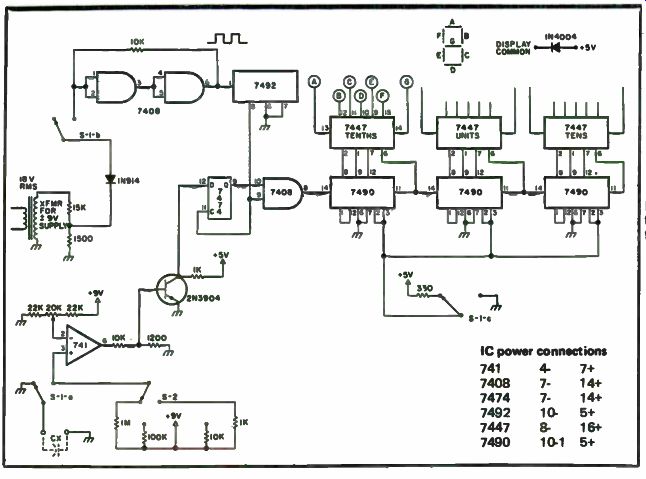
Fig. 4-13. S-1 shown in OFF position. S-2 shown in Times-One position.
... over some of the intermediate control circuitry and merely connect the 10 Hz to this three-digit divider-display chain, the display would consist of the right-hand digit showing tenths of seconds, the middle digit showing unit seconds and the left-hand digit showing tens of seconds.
You now have the comparator, the range switching and the 2N3904 interface. All you have to do is use it to stop the clock when the charge on the capacitor under test reaches the comparator reference voltage.
Interpose some logic circuitry between the 10 Hz pulses from the 7492 and the three-digit counter display as follows. A third section of the 7408 AND gate package is used as a gate. One side of this gate is fed by the 7492 with its 10 Hz output. The second output to this gate is a series chain of the output of the 2N3904 feeding into a 7474 D-type flip-flop used as a synchronizer. The output, A, of this flip-flop then goes to the 7408 section being used as a gate.
The 7474 makes sure that you always get a full final pulse or count through the gate no matter when the comparator triggers at the end of the measuring cycle. Note that its clock input is fed from the 10 Hz source.
Now let's take a quick trip through the whole shebang to see what happens when you measure a capacitor.
Suppose you have an electrolytic which is marked 6 uF and you want to check it. With the function switch in the OFF position, you connect the test leads to the capacitor, being careful to observe polarity. The test voltage does not exceed 5 volts. In passing, if the capacitor has not been in service, take the time to form it for a few short minutes at near its rated voltage, or your reading can be way out of the ball park.
Set the range switch to Times One, as this will basically measure up to 10 uF, which will be shown by a readout of 10.0 (this range will really go up to 99.9 uF, but it will take 99.9 seconds to do so, which makes another range more logical for a larger capacitor). When you throw the function switch to Test, things begin to happen.
The short is removed from the capacitor and it begins to charge. The 60 Hz is squared up and divided by six, feeding the gate and the synchronizer. The 7490 counter chain has had its reset bus grounded so that it can count any pulses coming its way. The output of the op amp is now highly negative, making the collector of the 2N3904 high (positive 5 volts). This high is applied to the D-input of the 7474, and the first low-to-high transition of the 10 Hz signal applied to its clock input causes its Q-output to go high (and stay high). This TTL high is passed to the clock pulse gate, causing 10 Hz pulses to be passed to the 7490 divider-readout chain, and the readout begins.
When the charging cycle finishes, tripping the comparator output positive, this makes the collector of the 2N3904 go negative. On the very next low-to-high transition of the 10 Hz clock which is applied to 7474, the Q of this flip-flop goes low, which shuts off the time pulses to the 7490 count display chain. Now you merely multiply the range switch setting by the indicated time on the display and you have your capacitor measured.
Now for a few notes on calibration: The range multipliers are in decade ranges of 1, 10, 100 and 1,000. As nosed on the schematic, the resistor values for these ranges are one megohm, 0.1 meg 10k, and 1k. Five percent resistors will do a decent job, but 1 percent resistors are preferred for aesthetic reasons if not for practical ones. Electrolytics are generally any thing but what is marked on the pretty package, generally erring heavily on the high side of what you think you bought. Oil-filled or large paper cups are generally truer to the mark, but, like all generalities, this can lead you astray. To start, let's assume that you have one favorite 5 uF oil-filled capacitor that you know is on the money (you checked it in the well-equipped CB shack of the guy next door). Connect it to the machine (ignoring polarity, as it is not electrolytic) and start a testing cycle naturally using the Times One range (one meg). If you have started out with the variable element of the voltage divider feeding the inverting input of the op amp set to the middle of its range, you will probably be close to the mark. Adjust this variable trimmer resistor on subsequent timing cycles until the display agrees with your known value of capacitor. Be sure that you have the function switch in the OFF position at least 30 seconds between successive measurements on the same cap to guarantee that it is once again discharged. If you do not, then your readings will vary. This is the entire calibration effort, for, if your range resistors are on the money, then the other ranges should be in good shape.
A good quality multiturn trimmer resistor is a must for the calibrating pot. Anything else will lead to frustration. There is nothing magic about the plus and minus 9 volts. My particular zeners came out at 8.8 volts, which worked fine.
The choice of readouts is optional. I used RCA DR2000 incandescent units, as Herback and Rademan was selling out some readout kits from RCA at an unreal $2.00 per digit, including PC board and decoder-driver IC. As shown in the diagram, the segments are fed through a diode to lower the 5 volts to about 4.2 under load. This way, the life is extended. LED readouts are perfectly acceptable according to personal taste; it just means that you have to add the usual current-limiting resistors to the circuitry.
An open capacitor will show no count a shorted capacitor will make the display count forever. This is handy, as it gives you a clock that counts up to 99.9 seconds for timing any event in that range. It could even have a darkroom spin-off for photo buffs.
Adrift Over Your Cs?
Once upon a time capacitors were nicely marked 0.1 uF or even 0.05 MFD. But now it is necessary to deduce their value from a rainbow of bands or spots, not to mention such numberings as 4k7, 5n, 5pj. Is that last colored band a figure in the value or a tolerance? Not to mention the useful collection of mica and other capacitors with obliterated markings and those with only a maker's number. Having some quite large tubular capacitors marked 5kp, in the expectation that they were 5,000 pF, or 0.005 uF, only to find they were in fact 50 pF, is quite frustrating. Here is a simple means of checking the values of doubtful capacitors.
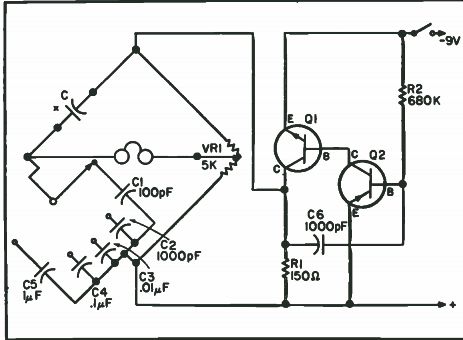
Fig. 4-14. This is the whole simple circuit, which isn't much.
The circuit of the result is shown in Fig. 4-14. Despite its simplicity it works nicely for values from 25 pF to 10 uF. Q1 and Q2 are combined to form an audio oscillator, output from Q1 being applied across the bridge.
The bridge has five capacitors for five ranges. Cx is the unknown capacitor. VR1 is a linear pot (it must be linear) for balancing, and high resistance phones indicate the null, so that the capacitor value can be read from the setting of VR1.
Oscillator. Assembly details will probably not matter much, but the audio oscillator can be wired on a tag strip. Both the transistors are audio or small output types, such as are available in great number and it is difficult to find two transistors which will not work here. Q1 must, however, be NPN, while Q2 is a PNP type.
A quite high tone is best. If necessary juggle with C6 or R2 or both to obtain this. The supply need not be 9v. The phones put across R1 will show how this works and two flying leads are soldered on to go to the bridge part of the unit.
Bridge. The five-way switch selects any capacitor C1 to C5. Without using the extreme settings of VR1, where accuracy falls, the center setting of VR1 is obtained when Cx is the same as Cl, C2 or so on. As an example, if C3, 0.01 uF is in circuit, the middle setting of VR1 balances the bridge at 0.01 uF for Cx. From here, the swing of VR1 goes from 1/10 to 10 times, so that this range is 0.001 uF to 0.1 uF. In the same way, C2 ( 1000 pF) gives a range of 100-10,000 pF, while C4 gives 0.01-1 uF and C5 gives 0.1-10 uF. C1 would by the same token provide 10-1000 pF, but the null or balancing point for VR1, easily audible with larger values, grows a little difficult to hear at the extreme low capacitance end of this scale.
It will be seen that the overlap is such that the same total coverage would be achieved with only Cl, C3 and C5. These three ranges would be 10-1000 pF, 0.001-0.1 uF and 0.1-10 uF. However, the extra capacitors C2 and C4 are well worthwhile to fill in for easy checking.
C 1 and C2 should be silver mica 1 percent items. For C3, a 2 percent or 5 percent item will probably have to be adopted. C4 may be difficult to get with better accuracy than 10 percent, unless costly, while C5 is actually two 0.5 uF tubulars in parallel. This means that calibration can be accurate for the lower values, but is less so for high values. In any case much accuracy is often not necessary with large values, except possibly in audio filters and some other applications.
These items are grouped mainly around the switch and the layout shown (Fig. 4-14) allows convenient wiring with the capacitors supported by a near tag of the audio oscillator section.
Case. A plastic box about 6" x 4" x 2" with insulated panel is most suitable. It carries an outlet for the phones, on-off switch, two terminals for Cx and a bracket to clamp the battery in position.
The scale for VR1 is marked 100 pF to 10k pF for C2 range and 0.01 uF to 1 uF for C4 range. The switch is marked pF and uF for direct reading of these ranges, and for uF x 10, uF 10 and pF 10 for the other ranges.
Calibration is carried out on the C2 range, with several known capacitors, preferably 1 percent, such as 100 pF, 250 pF, 500 pF and a few others. Values can be obtained by paralleling some, such as 250 and 100 for 350 pF, while switching to C 1 range allows the 100 pF, 250 pF and other low values to be used again for what will be 1000 pF, 2500 pF and similar 10x values on the C2 range.
No calibration is made for the large capacitor ranges, as these will be progressively 10x the existing ranges (assuming C3, C4 and C5 are accurate enough). A clip or two on short leads from the terminals will be handy for some capacitors. Simply rotate VR1 for the null and read the value on the scale.
High impedance phones, in the 2k to 4k range, will be best. A dip but no real null shows leakage and is to be expected with electrolytic capacitors.
The Capacitor Comparator
If your junk box is tucked way back in the corner in a spot where you throw all those unmarked, unidentified capacitors that you just KNOW will come in handy some day, then this project is for you. Round ones, square ones, flat ones, fat ones, piston and bypass ones and those a guy could have a great time screw-drivering if he just knew where to use them are probably all in your box.
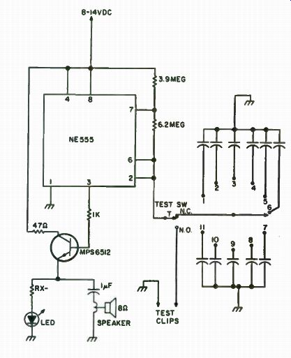
Fig. 4-15. LED indicator and RX-see LED specs. Capacitor bank: 1 = .7 pF;
2=3 pF:3 = 5pF;4 = 10 pF; 5=25pF:6 = 50pF; 7 = 100pF; 8 = 330 pF; 9 = 470pF:
10 = 680 pF; 11 = 820 pF. Test switch-SPDT push-button.
This simple circuit is an easy one-evening project that when completed will provide an audio tone comparison of a built-in reference capacitor to an unknown capacitor connected to the test clips. Bearing in mind that the larger the capacitor the lower the tone, it is a simple matter to establish the value of unmarked units. The circuit (Fig. 4-15) will identify caps between . 5 pF and . 001 uF by providing tones between 8 kHz and 100 Hz. The heart of the tester is a 555 timing IC and may be operated from any DC voltage source between 8 and 14 volts.
An LED indicator is provided for testing values larger than . 001 uF which do not produce a tone but merely turn the LED off and on. A.1 uF unit will trigger the indicator at approximately 5 Hz.
Piston, compression and rotary trimmers may be identified by first making a comparison fully closed and then fully opened. Small gimmick caps made from twisted leads are also easily sized.
The LED is, of course, optional, as well as the number of reference capacitors. Any NPN switching or audio transistor may be used in place of the MPS6512. If the LED is not needed, the transistor may be eliminated and the speaker with its 1 . uF coupling capacitor is connected directly to pin 3 of the IC. Why not try a Poly Paks unmarked assortment at 100 caps for $1.98? Computerized Capacity Meter Caught up in the hacker frenzy while attempting the design of some higher-order active filters? If you have ever spent more than a few hours programming an SR-52 to solve cubic and quartic equations, you have realized that some heavier-duty number-crunching was called for if you really wanted to obtain those steep skirts. If you head to your local friendly computer store, you will return several hours later with several heavy boxes and one extremely light wallet.
The kits will go together surprisingly well and produced only a couple of minor bugs.' You may now also need several close-tolerance capacitors. But if you do not have any kind of a bridge for measurement and if the state of your wallet precludes the purchase of such an instrument (or even the cost of several 1 percent capacitors for a one-off filter), you can make use of items you find in your junk box to build something that would do the job with a little assistance from the computer.
Overall Design Considerations.
The design considerations are simple:
• It has to be extremely cheap to build.
• It has to be extremely easy to build.
• It has to use a minimum of both hardware and software.
• It has to be reasonably accurate.
The resulting circuit uses only three readily-available components, a small machine language routine (which can be called from BASIC) and the accuracy is limited only by the clock speed of the computer system being used (Table 4-4). Figure 4-16 offers a thorough description of the method with a flowchart. This enables the system to be tailored to any computer.
Circuit Design. The circuit consists of a 555 timer chip wired in a standard monostable configuration (Fig. 4-17). Circuit Operation. The monostable is triggered under control of an output port bit. Triggering the 555 requires a trigger signal going from a high (+5) level to a low (0) level for a brief period and then returning the trigger signal to a high level (Fig. 4-18). The monostable now switches its output to a high level and this level is sampled at an input port until the monostable times out. While the monostable is timing out, a count is made. This count is ...
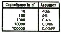
Table 4-4. Assuming count loop for one count is approximately 20 microseconds.
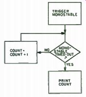
Fig. 4-16. Flow chart.
... software scaled to equal the value of capacitance that determined the length of the monostable (Table 4-5). Software. The whole program can be written in machine language using very little memory, or the count routine can be inserted in memory and called from BASIC via a USR or CALL statement. The example shown in Table 4-6 uses a simple BASIC routine which can be expanded to the desired esoteric level. The count from the monostable is averaged over ten triggerings and the resultant count is then multiplied by a calibration factor to give the value of capacitance used. This count may then be output in whatever form you may choose.
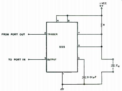
Fig. 4-17. Standard monostable configuration.
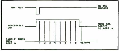
Fig. 4-18. Trigger Signals.
Calibration. Insert a known value of capacitance in the circuit and run the calibration program (Table 4-7). Enter the result from this program into statement 80 of the main program (Table 4-6). Stray capacitance in the test leads can be calculated by running the program without a capacitor in the test leads and changing the BASIC program to compensate. (Don't forget that you are averaging 10 triggerings!) The representative listing (Table 4-5) is from a hobbyist's read boarded setup attached to a parallel port, using the high-order data in/out bits. For breadboard purposes, a line was run from the bit 7 data out to the trigger input and fed the monostable output to the bit 7 data in. The other lines were left floating, which accounts for the bit structures you see addressed to the port in the machine language listing.
Using a 4.7 megohm resistor, the breadboard setup measures from less than 100 picofarads to better than 0.1 microfarads. If you need to cover a larger range, you need only change the value of the resistor and recalibrate. Out-of-range detection can, of course, be accomplished by inserting a software routine to check for a carry during the count and return you a message to change ranges when this occurs. Again, be cautioned, any increase in the size of the count loop will affect the accuracy of measurement.
Timing considerations for the 555 in a monostable configuration are given by T = 1.1 RC. Because of this relationship, this circuit can also be used to measure resistance, though it then needs to be calibrated with a fixed value of capacitance.
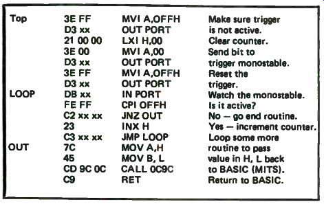
Table 4-5. Program A.
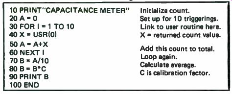
Table 4-6. Program B.
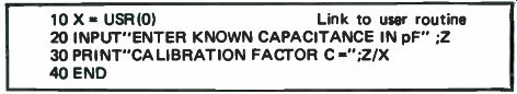
Table 4-7. Program C.
Reincarnating Old Test Equipment
(A 1942 capacitance meter is born again in this project.) Purchased in 1942, the model BN cost about $12.00. Eighteen years later, the 12A7 failed and was replaced. In 1972, a resistor failed, and then, in May 1977, the new 12A7 failed. Obviously such an unreliable piece of gear was begging for replacement-until the price of an equivalent unit revealed the true extent of inflation. The only item needed to bring the unit back to life was a bridge balance amplifier and an indicator of balance. Some people have never been thrilled with the magic eye indicator, as it has to be shaded from ambient light to really see when balance is achieved. New housing was provided by a cabinet from an old 5" Sony TV. It was mated to a panel made out of a Formica cutoff from a woodworking project. Figure 4-19 shows the original schematic.
Electrically (Fig. 4-20), all parts associated with the old bridge amplifier and magic eye indicator were discarded, keeping the basic bridge components intact. The voltage divider, consisting of a 10-megohm resistor and a one-megohm resistor (across the output of the bridge), serves two pur poses. First, it keeps the impedance high at this point and allows the bridge to function. Secondly, it controls the amplitude of the input to the op amp used as a bridge amplifier.
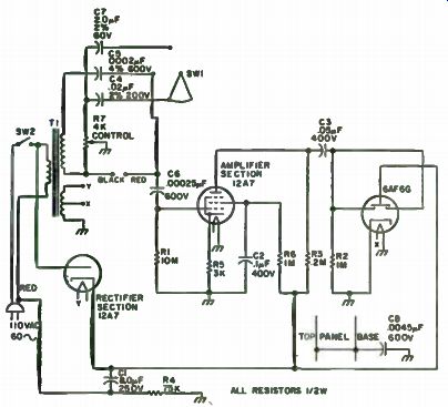
Fig. 4-19. Circuit diagram for capacitor bridge model BN.
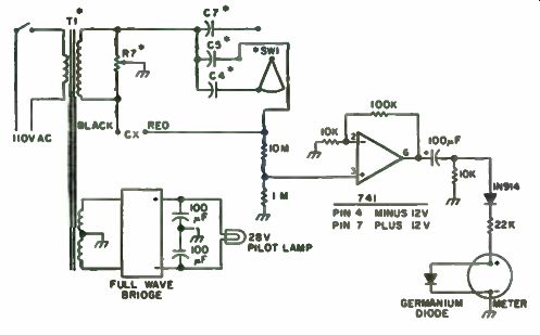
Fig. 4-20. Original components.
The output of the bridge when unbalanced can run as high as 30 volts, and at balance, depending on the range in use, can be as low as a few tenths of a volt. The divider reduces this variation of amplitudes by a factor of 11 to 1 void real problems with the op amp, which is set up for a gain of 10.
The balance indicator is a meter salvaged from an old tape machine and serves quite nicely in this function with the advantage over the old magic eye in that it does not need to be shielded from ambient light. Here is a simple way to set up the proper series resistor to scale the meter. Unbalance the bridge and insert just enough series resistance so that the meter pins full scale. Then shunt the meter with the germanium signal diode, as shown in Fig. 4-20, and the meter indication should drop about one or two scale divisions. This simple method obviates any fuss and feathers log amp problems to handle the signal variations that the op amp handles. It allows for a very nice null reading to show balance, while saving the meter from overload.
The original transformer has two windings-one driving the bridge and the other a center-tapped winding which formerly lit the filaments of the tubes. This latter winding is used to feed a full-wave bridge, producing the DC voltages needed for the 741 op amp. Putting a 28-volt pilot lamp across the output of the supply serves the second purpose of acting as a bleeder.
Be sure to ground the dial plate of the bridge to the ground terminal of the supply. If you use a metal cabinet, keep the bridge circuitry isolated from it, as it may upset bridge calibration on the low capacity scale.
--
Next: Resistance and Impedance Measurers