Build A Bridge to Measure Transformer Impedances
This project is for those who are scared silly at anything that even remotely resembles an algebraic formula. If you have several transformers around your workshop that are unmarked, you'll enjoy this project. Three pieces of equipment are needed, two of which you probably have. The first is a signal source at about a 1,000 cycles (you can use 60 cycles in a pinch), since most audio transformers are measured at this frequency. The source should have an output of about 5 to 10 volts, although it can be less if you use a sensitive oscilloscope for the null detector, which is the next piece of gear that you need. You can use a VTVM, a scope, a simple old 6E5 magic eye null detector, or (if you have enough signal) an AC micro-ammeter (not recommended). The third and last thing that you will need is an instrument improperly called a Wheatstone Bridge.
Please don't rush for your pen to defend old Sir Charles Wheatstone.
We're not trying to deprive him of his place in history, but the fact is that he just didn't invent the darn thing. True, he publicized it, but the device was invented by an English scientist named Samuel H. Christie in 1833. At any rate, this simple piece of gear is the solution to not only this problem, but to so many others on the workbench. Considering its simplicity (Fig. 5-1) it is perhaps the most valuable instrument that you will own.
Now for the construction data, which will be meager because no one will build a carbon copy anyway. First, don't use a standard volume control for your calibrated pot. They are just too small to permit any degree of accuracy. The potentiometer is a 5 1/2 " diameter, wire wound, 10k ohm log taper job. You don't have to have one that big, but try to get a pot over 2" in diameter.
Wire with heavy leads, the heavier the better (# 14 wire) and make sure that you use well-insulated binding posts. Also, be sure that your signal input connector is well insulated from the chassis. Plug-in resistor jacks are made using banana plugs on pieces of Lucite. The only other components that you will need are some precision resistors and capacitors, preferably 1 percent (Table 5-1). The accuracy of the instrument depends on two things: the precision with which you calibrate your dial and the accuracy of the standard resistors and capacitors that you use.
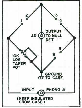
Fig. 5-1. Schematic.
You can make the dial 6" in diameter using a large skirt knob and a flange from a daylight load spool from 16mm movie film. File a flat on the shaft of the pot so that the dial will never slip and it will retain its calibration if it should ever have to be removed. After the instrument is assembled sit down with a handful of precision resistors and a VOM to calibrate. Hook the ohmmeter across terminals # 1 and #6 and mark the dial carefully with a pencil, checking every reading against a known 1 percent precision resistor wherever possible. You can also apply white press-on numbers and dots and spray them with clear lacquer to protect them. The calibration procedure is not difficult, just tedious. Calibrate the major 1k ohm points first then the 100 or 200 points in between. The more careful you are, the more accurate your bridge will be.
Use standard RCA phone jacks for input and output. Using them whenever possible on projects is a good idea because of the wide variety of shielded cables available that match them.
Just one more thing on construction before we get to the good part.
Space the banana plug posts a standard 3/4 " apart. That way you can use standard dual banana jack instrument plugs. It doesn't affect anything; it's just a matter of looks.
It's difficult to' believe that such a simple device can really work so well. Don't be disappointed if at first you are testing an audio transformer with a known impedance of 10k ohms and you don't get the correct reading with your new tool. The other winding also should be loaded to its proper impedance in order to get an accurate reading on the winding under test.

Table
5-1. List of Required Standard Resistors and Capacitors, 1 percent.
Hook up a four ohm resistor to the output winding and it will measure 10k ohms on the primary. Since four ohms is a pretty low resistance, what do you think would happen to the impedance of the other winding if you were to short the four ohm winding? Try it. You'll now measure approximately 1,800 ohms across the primary. Could it be that shorting the low impedance winding gives you a reading of about one-fifth of the true impedance? Subsequent tests with other transformers show that, although this is not 100 percent accurate, as a general rule of thumb you might use this as a ball park figure to start.
Start by measuring the DC resistance of all windings with an ohmmeter (or with the bridge using the described procedure for DC resistance measurements) and marking them. If you are sure that it is an output trans former, hook a 4 or 5 ohm resistor across the lowest resistance output winding. Connect the high resistance winding across the #5 and #6 terminals of the bridge, a 1 kHz signal to the input and a suitable detector to the output. Measure the resistance and hook a carbon resistor of this value across the winding you have just measured. Reverse the transformer and measure the previously shunted low impedance winding. If it was an output transformer and you had used the 4-5 ohm shunt, you will probably find that you are within 5 to 7 percent of the true value of the transformer. Close enough for all practical purposes.
If you are not sure of the type of transformer you are working with, then proceed as follows. Short the leads of the lowest resistance winding together and connect the highest resistance winding across the bridge.
Measure and multiply the reading you get by six and connect a resistance of that you just measured. Now reverse the transformer, measure the previously shorted winding, connect a resistor of that value across it and repeat the procedure on the high impedance winding. It only takes about two or three measurements, going back and forth from one winding to another, to achieve a remarkable degree of accuracy. Practice on a few transformers of known value and if you find your readings coming out wrong, look for shorted clip leads or open connections. With a little practice and care you can solve your unknown transformer problems.
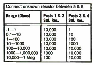
Table 5-2. Resistance Measurements. Connect unknown resistor between 5 & 6
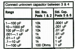
Table 5-3. Capacitance Measurements. Connect unknown capacitor between 3 & 4
It will interest you to know that you can also measure carbon and wire wound resistors to a very high degree of accuracy using DC current. First connect a source of DC, a battery or other supply of from 1 1/2 to 4 1/2 volts to the input jack with a push-button in series and a 0-50 or 0-100 DC center scale micro-ammeter to the output jack. Hook the standards and the un known up in accordance with the resistance chart of Table 5-2. Using the push-button for momentary contact, start rotating the dial until you start to get a null, after which you can hold the button down to finalize the null.
Using an audio oscillator you can also measure capacitance (Table 5-3) and inductance (Table 5-4). Just remember to keep all test leads as short as possible, make tight connections. Also, be careful of shorts and open connections.
A Simple RC Substitution Box Using a Matrix
Those experimenters who are constantly engaged in circuit experimentation or development work have probably purchased or built elaborate R and C substitution boxes. Such substitution boxes greatly simplify the problem of finding just the right component value to use to optimize circuit performance for any desired condition (maximum gain, bandwidth, stability, etc.). For those who just occasionally build some accessory circuits, substitution boxes would also be very useful when a given circuit doesn't work exactly as it should or when one wants to determine if an available component will do in place of a specified value. Unfortunately, cheap RC substitution boxes don't buy you too much. The increments in which they cover RC ...

Table 5-4. Inductance Measurements. Connect unknown inductor between 1 & 2
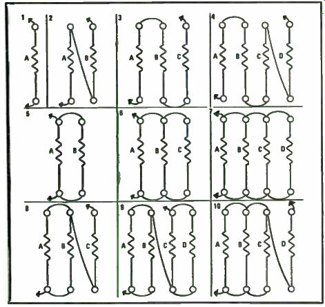
Fig. 5-2. Interconnection diagrams for four resistors in substitution matrix.
... values are usually too large and calibration can be poor. One can substitute potentiometers for fixed resistors in a circuit, but their calibration is poor and one has to constantly check the value of a setting with an ohmmeter. The result of all this is that most occasional circuit builders end up soldering components of a fixed value into a circuit and by trial and error arrive at a successful result or a hopeless jungle of tack-soldered components.
This simple matrix can solve those problems for the occasional circuit builder at a very low cost and still achieve accurate results.
Most RC substitution boxes, whether they be for resistance or capacitance substitution, make use of switches to select components of various values. However, another approach would be to take a fixed number of components (R or C) of different values and hook them up in as many ways as possible (series, parallel, series/parallel, etc.) to obtain a succession of different overall values. However, how many fixed values should be chosen to keep the circuit complexity within bounds? What should their individual values be both to obtain a good overall substitution range and have a smooth progression of resultant substitution values? We'll let a computer solve some of the latter questions. It's not surprising that a computer comes up with a "binary" type answer. We'll use resistors to demonstrate the idea, but it is equally applicable to capacitors.
Take four components (resistors) of value 10, 20, 40 and 80 ohms and let's see how many different ways they can be interconnected. The interconnection possibilities are illustrated in Fig. 5-2, starting with the simple use of one of the resistors alone and then various series and series/parallel connec tions: There is nothing new about these circuits, but what is interesting is what happens if one tries all the circuit possibilities and then arranges the resultant values that can be achieved in order. The result, as shown in Table 5-5, is a wide, smooth range or resultant values going from 5 ohms to 150 ohms. Four properly chosen resistors have resulted in the equivalent of almost 40 different resistor values progressing in very even steps over a 30 to 1 range! Table 5-5 is, in fact, a universal value table. It shows resistance values of 5 to 150 ohms being achieved by four individual resistors of 10, 20, 40 and 80 ohms. But, it can be scaled up or down to achieve different ranges with other, similarly ordered values of individual resistors. For instance, the following would be the range of values achievable with the resistors shown:
• 0.5 to 15 ohms-use 1, 2, 4 and 8 ohm resistors
• 50 to 1500 ohms-use 100, 200, 400 and 800 ohm resistors
• 0.5k to 15k ohms-use 1k, 2k, 4k and 8k ohm resistors
• 15k to 150k ohm-use 10k, 20k, 40k and 80k ohm resistors
• 150k to 1.5 M ohm-use 100k, 200k, 400k and 800k ohm resistors
The resultant values can be checked by anyone using the usual series/ parallel resistor formulas for any of the circuits shown in Fig. 5-2. A more practical question might be how to implement the idea in a simple, reliable form. One could, of course, devise a special switch to achieve all the hookups shown in Fig. 5-2. Some manufacturers capitalized on this idea.
However, a simple home brew way to arrange the four resistors in any of the circuits shown in Fig. 5-2 is to use a simple plug and jack switch matrix as shown in Fig. 5-3.
Four columns of six plugs each are used with the individual resistors inserted in the positions shown. The lower "output" terminal is fixed at the bottom of the "A" column. The upper "output" terminal is connected via a flexible wire so it can reach any of the plugs on the upper row of the field. By moving the latter jack wire, plus the use of a few jumper wires between columns, any of the circuits of Fig. 5-2 can be wired. With a little practice, one quickly develops a system to go from one circuit configuration to the next.
The matrix of Fig. 5-3 can be built on any insulating material (perforated board stock or plexiglass), using inexpensive noninsulated plugs and jacks.
One could permanently solder in the resistors, but if they are made "plug in", the same matrix can be used for different resistance ranges by plugging in different sets of four resistors. The matrix board is a neat and orderly way of interconnecting the four resistors. But if one had to do it, they could also be interconnected using simple jumper leads by keeping Fig. 5-2 and Table 5-5 handy for reference.
Standard value resistors do not come in all the desired values (4k and 8k, for instance). Choose the closest available values to those shown (3.9 and 8.2k, for instance), but measure them once with a good ohmmeter.
Usually resistance values, unlike capacitor values, are well within the manufacturer's stated tolerance. Standard, inexpensive 10 percent tolerance resistors should work fine for most circuit work. But, again, check them first before relying upon them. The tolerances can either build up or cancel out in the various series/parallel circuits. The power rating of the resistors used depends upon the circuit applications intended. For most low level transistor circuits, 1 or 2 watt resistors will certainly suffice. If one obtains the four resistors for the 0.5 to 15 ohm range, they should be of the 10 watt size since they will most likely be used for power supply or audio power amplifier circuit applications.
What about using the matrix for capacitor substitution? Of course, series and parallel resistor circuits have their equivalent in parallel and series ...
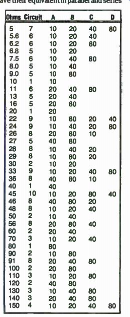
Table 5-5. Circuit Numbers Refer to Those Shown in Fig. 5-2.
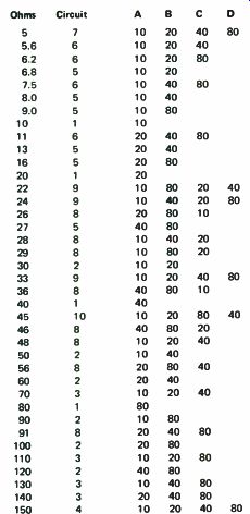
Fig. 5-3. Matrix panel suitable for either resistor or capacitor usage.
... capacitor circuits. The circuits of Fig. 5-2 and Table 5-5 can be used if one remembers the equivalent circuits. For instance, for 150 ohms Table 5-5 calls for the use of circuit 4 in Fig. 5-2, which is all resistors in series. If one wanted 150pF (using individual capacitors of 10, 20, 40 and 80 pF), the equivalent capacitor circuit is used. Connect all capacitors in parallel. For 5 ohms, Table 5-5 uses circuit 7 and connects all resistors in parallel. For 5 pF, connect all capacitors in series. For 30 ohms, Table 5-5 uses circuit 9 or AB parallel in series with CD parallel. For 30 pF, use AB in series and then parallel with CD in series. Table 5-5 can be scaled up or down for capacitors the same as it can be for resistors. The total range for each set of four capacitors will remain a 30 to 1 range: 5 to 150 pF for fixed capacitors of 10, 20, 40 and 80 pF, 0.1 to 3 uF for fixed capacitors of 0.2, 0.4, 0.8 and 1.6 uF, etc.
Unfortunately, capacitors, and especially electrolytic types, vary widely from their marked value. Tolerances of up to - 20 and +40 percent for electrolytics are common. One can build a substitution matrix using disc ceramic or mylar capacitor and rely upon the capacitor values to be close enough to their nominal values for general substitution work. In practice, this means a substitution matrix going up to about 1 uF maximum. Beyond this value, when one has to use electrolytic capacitors to build the substitution matrix, it is imperative that the actual capacitor values be measured if the substitution matrix is to have any reasonable accuracy.
This describes a simple individual R or C substitution matrix. If the resistors or capacitor sets are made for plug-in use, the matrix of Fig. 5-3 can be used for either type of substitution as required by an individual circuit.
With a few matrix boards and several sets of resistor and capacitor plug-in sets, a handful of components can be used to replace several hundred for substitution, testing and experimental purposes.
Finally, how about RC combinations such as time constant circuits, low pass and high pass filters? These can also be built for various values and frequencies by combining R and C elements on one or more matrix boards.
The variety of values here is so broad that it is impossible to define any table for them. However, by using the known R and C values for the individual RC substitution boards and standard formulas, one can easily develop a duplicate-able set of response configurations usable for a wide variety of circuit experimentation.
Megger for Peanuts
During WW II days, a certain landlady named Gladys had goldfish in a big aquarium, had a husband Al, a two-year-old Carol and a cat. She had noticed an attrition in the goldfish to the feline. She was, however, realist enough to suspect her baby daughter too. As the resident electronics expert, could I invent something that would determine guilt or repel- without harm-the culprit? The basic scheme was to connect the light line between a ground screen (you could get galvanized iron screen in those days) and the water itself. The fish and the pipes would probably ionize the water enough.
Obvious enough, but there remained safety considerations. The kid was a card, and definitely not expendable. Limiting resistances, sure, but how big? I had heard 15 mA put forth as the least amount of current, applied directly across the heart, that would be fatal. Since this stated a unique value, not a range, I had little faith in it. Human beings vary at least three to one in susceptibility to inimical influences, whether electric, ballistic, chemical or a knock in the head. Taking 15 mA as a point to depart a long way from, a megohm in one side of the line seemed like a conservative place to start.
But the direct other side-how could I make sure the other side stayed grounded? Simple: duck the problem, put a meg in each side.
I tested the system while Gladys and the goldfish watched curiously.
I didn't expect to feel much, considering the decoupling resistors. But I did expect to feel something, if only a tiny tingle. But still thinking of the baby, I decided to leave the setup alone for a few days before dropping resistance values.
Gladys counted her herd every day and gave me the unchanging total each day at the supper table. One evening we discussed the goldfish and decided the cat was making fools of us. Al caught the cat and gave her to me.
Kitty didn't know what was coming, but she suspected she wasn't going to like it.
Taking her firmly by the neck, I pushed her head so that her nose would barely touch the surface of the water. At the exact instant of contact, she jerked. I tried it several times. It seemed to me that here was biological electrical rather than nerve response.
Gladys said, "Aw, the poor kitty-," took her from me and shoved her whole face under the water. The cat exploded out of her arms and escaped.
Puzzled, I dipped my finger in again, contacting the ground screen with my other hand. If I got hit, I'd at least fall clear. Nothing. I was conscious of my audience-Al, Gladys and the fish. I stuck my own nose into the water.
Nothing. I stuck my tongue in the water and the fish backed away. Nothing.
Not even the coppery taste you get from a dry cell.
We concluded that the setup was working, though it was hard to see how. Obviously, the cat had a horror of that tank. Cats smell very well, though their noses are isotropic. They often miss a bit of food within reach, while a dog scans, goes into a hunt and locks on in practically one motion. But maybe we had an entirely new biological phenomenon here. Was a cat's nose a supersensitive indicator of an electrical charge? It certainly seemed so.
The limiting effect of a resistance is instantaneous. The system was a big voltage divider and the better the contact, the less voltage drop.
I forgot all this for 20 years. I wound up on h microwave test bench and found out a lot of other things. You've heard of the Miller Effect? Ever see any evidence of it? I did. The 70 meg i-fs would occasionally exhibit it and until I caught wise, drove me up the wall. The cause was defective bypass capacitors which could fail in a variety of ways. They could go open or shortened, or just lose their capacitance. These were button-mica feed through types. We were furnished an excellent GR electronic megger. It would measure megohms up in the hundreds or thousands. When a bypass had as little as one meg resistance to ground, it was time to get rid of it. The 250 volts and the heat would break it down in a couple of weeks and you'd get the amplifier back from the field. This was not good. The best solution was to replace every cap after the amplifier was in service for a couple of years, but there simply wasn't enough stock to permit this.
Good as it was, the GR megger was too much instrument for the job.
What I needed was something simple, something cheap. It should be small-the GR took up too much bench and was heavy and clumsy.
The first design worked very well in practice. The basic standard was my wristwatch, which gave me better than one part in 720 accuracy.
Lighting juice went into the little plastic box to a DPDT switch. Thrown one way, it merely lighted a red pilot light (neon). The other way, it connected it through a diode to a filter capacitor for a primitive power supply. A pot regulated the voltage. The slider went through a one meg limiting resistor to a binding post. The ground side of the pot went through a timing capacitor and another one meg resistor to the other binding post. Across the capacitor, an NE-2 bulb.
After the first few days, I forgot all about calibration, except for the most basic adjustment. What I needed was a go-no-go instrument and I really had one in this gadget. All I really wanted to know was, would the cap work for a few months, or should I replace it? Twenty megs or 200 would be fine. Ten wouldn't.
Of course, theory-wise, you are way ahead of me. It is a time-constant deal; when the voltage rises to 63 percent of the input voltage, you have one time constant, whether it is one Farad and one ohm, or a megohm and a microfarad, right? There is something about that 63 percent. Maybe here it suddenly becomes more horizontal than vertical-the charging curve. Any way, an oscillator will come out to pretty close to the calculated time constant value. And the NE-2 is both a relaxation oscillator and a timing indicator, right? That's what I thought. There is a time constant that uses 63 percent right enough, but the time constant this gadget uses is very far from the classic one. Instead, it is time taken for the NE-2 to fall from the firing voltage of maybe 70 volts to the extinguishing voltage of about 69. You get approximately a one volt spread between these values. Of course, the timing capacitor size, the limiting resistor sizes and the charging voltage are all factors. If you are looking for resistance, then you juggle voltage and timing capacitor size until you come up with the proper value. Of course, it is most convenient to vary the voltage with a pot.
It surprised me that the ionize-non-ionize range was so small. I expected the voltage to drop to 15 or so. The CRO sweep tubes. 884/885/6Q5 will, but remember, they all have hot cathodes and this makes all the difference.
In actual use, I discovered that the safety switch was as useless as the well-known complementary accessories on the bull. Knowing that I couldn't possibly be hit, I was unable to remember the switch and found my fingers all over the external wiring. It was time for a new model. Perhaps a true go-no-go model without any adjustments? No, this was too radical. A pot and a knob and a hole to look through-that was the idea! And while I was about it, why not get rid of those silly binding posts? The other change was to use standard commercial 8-lug strips rather than individual miniature standoffs (Fig. 5-4). Still another was to use shallow grooves in the plastic box ends for the AC input cord and for the output clip-cords. I once knew a man who claimed that if you wanted to blow fuses, the best gadget for this was the standard alligator clip. He is right, beyond question, but in this case, with the load dead, it doesn't matter if the clip slips. And it saves a lot of bother with binding posts, which will eventually have clips leads on them anyway.
One thing I learned from commercial equipment: a 1/4 watt, 100 ohm resistor makes an excellent fuse and protective device. Sometimes they shatter explosively, leaving only the leads. Sometimes they crack invisibly and you find blown ones by twisting them with flats. Or, they may cook and spray the whole inside with bakelite varnish. No question what happen ed, the stink tells you. You can remove varnish and stink with mineral spirits (kerosene). They serve another purpose--they limit the peak charging current through the diode.
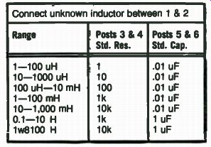
Fig. 5-4. Schematic.
The model illustrated in Fig. 5-5 is the NE-2 (actually Japanese). It was originally taped to the paper clip, to a ground lug, which cannot be used for active connections. There are two of them. The panel has a 1/2 " hole for viewing the neon. The two straps short out padding resistors in the voltage-adjustment circuit which were not needed.
Calibration is a cinch. Short the clips- with your fingers if you like- and adjust the pot for the firing rate you want. Say, 10 flashes in 20 seconds.
Put you wristwatch next to the gadget and count flashes seen in your peripheral vision. This is a lot easier than it sounds, because every flash is equally bright, no matter how long you have to wait for it.
I have waited for minutes at a time to measure really high values, but for my purposes, this is time wasted. Who cares about hundreds of megohms? Now, with 10 flashes in 20 seconds you are timing out at one second per megohm, and actually accounting for the safety, or limiting resistors in the box. Naturally, you start your count with a flash, and then count 10 more, excluding the start, or zero flash. Now if you have one, stick in a ten meg resistor. What would your timing be now? Twelve seconds between...
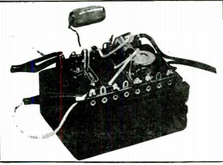
Fig. 5-5. Completed project.
...flashes? That's 10 on the outside and two inside. How about one flash after 19 seconds? Maybe you don't want to wait 19 seconds. Then calibrate Y2 second per megohm. Or any other value you want. The instrument is surprisingly linear over a reasonable range, mostly because of its limited voltage excursions as it oscillates. In theory, when the external resistance being measured exceeds the leakage resistance of the calibrating capacitor, and it's got some, the said capacitor never will charge up. It will just sit there, discharging as fast as it charges. Don't worry about it-you are not likely to experience this effect.
All right, you built yourself a megger. What good is it? The first thing to do is pick a holiday-your birthday, 4th of July, whatever. On this day you measure the insulation of your refrigerator, your air-conditioner, furnace motors and don't forget your electric drill-they are killers because you are wrapped up around them in use. Don't forget the wife's kitchen either - stove, mix master and iron. Write down all the values you can read. Next year, do the same thing or sooner if you like. Does any of them show a marked drop in the winding-to-ground value? Dump it. Get a new one. It could save a life. The box probably will save you money, maybe 50 times its cost. If it does, you'll be a believer from then on out.
A VOM or a bridge is a multi-purpose instrument. I dislike other examples; however, too often an additional function just complicates an instrument and makes it expensive. For instance, you could set up the megger to measure small capacitors. Please don't. Leave the "high current" high voltage in that box where it belongs.
But I did have a very odd use for the megger. I was investigating hum sources in a Kellogg 40.1 vacuum tube. I tried various connections and discovered that the insulation in these was very good, whether the tube was lighted or cold. The bright ends of the heater wires looked interesting, so I measured and got a nice reading- 50 megs -in the conducting direction.
Assuming 60 volts, this gave me 1.4 microamperes between heater end and the plate support rods. This is a significant source of hum.
As far as I know, there are only two of these gadgets in the world. If they became popular, there might be two or three in a large city. Why wouldn't these little boxes be a perfect present for the man who has everything else? If he fixes TVs as a hobby and likes to measure leaks in coupling capacitors--yes. He'd appreciate one-any real technician would. But never think you could persuade a non-technical type to measure the electrical equipment around his house. To him, it would be pointless. To gift such a man with one of these is to provide a source of embarrassment to both of you.
--
Next: Testers for Solid-State Components