DVMs Get Simpler and Simpler
With all the interest in digital electronics, and with prices of the related parts dropping, it seems natural to that much of the equipment in labs could be " digitized. " The result would be that equipment would be much easier to read (no analog meters to interpret) and perhaps the readings would be more accurate. This is part of the justification for this project. It is the design of a digital voltmeter that is cheap and easy to build. It should be included with your power supplies, communications gear, etc. It would also be nice to have a digital multimeter, too.
You may be aware of the fact that many semiconductor houses offer digital voltmeter chip sets. These consist of an analog to digital converter chip and a digital counter array chip. All you have to add, at the most, are a power supply, a system clock, a reference source and a display system.
That can easily mean six chips and up! This means high cost and lots of construction. But there is a better way.
Motorola has introduced a chip set that requires only a power supply and a display system. It's easy to work with and easy to calibrate. And the best part is that it's available and cheap (under $18 for the set), too! Accuracy is rated at 0.05 percent and that is probably worst case! Your voltmeter accuracy will depend upon the accuracy of the standard you use.
This project you are about to build is the system the "Cheap and Dirty DVM" is based on.
Some of the disadvantages of the DVM should be mentioned. The first one is that it won't measure negative voltages. You have to reverse the input leads for that, like on an analog VOM. The second disadvantage is that the chip set has an input impedance of 4k ohms, but this is changed to 10 megohms input with a $2. 00 op amp in this unit. None of these problems are serious--the first requires a quad op amp and some parts. The second has already been taken care of. If you want to read further about the Motorola chip set, call or write them for the data sheets.
Construction isn't too difficult, but there are several areas to watch.
Probably the biggest problem you will have is finding a box to house the finished unit. If you want a general purpose meter to be used around your workshop, a minibox will work fine. However, if you want to build a digital panel meter to be installed permanently in a piece of equipment, you are in a sticky situation because digital panel meter cases are very hard to get. Use a small minibox if you're stuck. Cut a rectangular hole in the front of the box and put a red filter behind it. Then cut and bend aluminum stock into two L brackets large enough to fit on the ends of the box. You could then cut a hole large enough to accommodate the box front in your panel and use the L brackets to secure it. Possibly a better way would be to make up an aluminum plate larger than the front of the box and use it to secure the box to the panel. You would have to duplicate the display cutout in the plate, of course, but the result could look pretty neat! If you have never built a digital voltmeter before, you are in for some interesting construction! If you have, these construction hints will sound ...
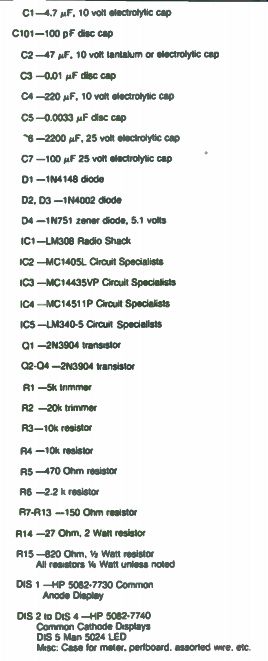
Table 7-1. Parts List.
---------------------------
C1-4.7 MF, 10 volt electrolytic cap C101-100 pF disc cap C2 -47 uF, 10 vet tantalum or electrolytic cap C3 -0.01 uF disc cap C4 -220 µF, 10 volt electrolytic cap C5 -0.0033 uF disc cap
'6 -2200 µF, 25 volt electrolytic cap C7 -100 µF 25 volt electrolytic cap D1 -1N4148 diode
Q2. Q3 -1N4002 diode D4 - 1N751 zener diode, 5.1 vats IC1-LM308 Radio Shack IC2 -MC1405L Circuit Specialists IC3 -MC14435VP Circuit Specialists IC4 -MC14511P Circuit Specialists IC5 -LM340-5 Circuit Specialists
Q1 -2N3904 transistor
Q2-04 -2N3904 transistor R1 -5k trimmer R2 -20k trimmer R3-10k resistor R4 - 10k resistor RS -470 Ohm resistor R6 -2.2 k resistor R7- R13 -150 Ohm resistor R14 -27 Ohm. 2 Watt resistor R15 -820 Ohm. 1/4 Watt resistor All resistors 1/4 Wan unless noted DIS 1 -HP 5082-7730 Common Anode Display DIS 2 to DIS 4 -HP 5082-7740 Common Cathode Displays DIS 5 Man 5024 LED Misc Case lot meter, perfboard. assorted wire etc.
---------------
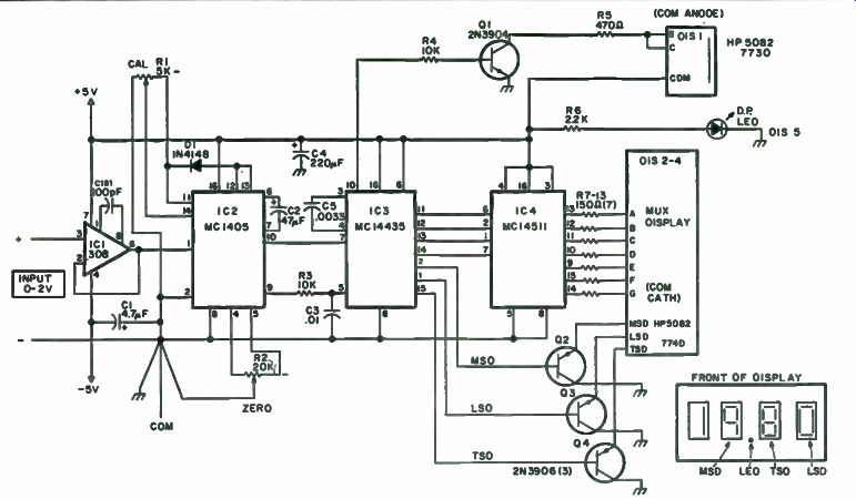
Fig. 7-1. Basic meter.
------------------
... familiar. The layout isn't too critical, and the parts may be placed nearly anywhere. For a complete parts list, see Table 7-1. The heat generating power supply should be located as far away as possible from the MC- 1405 chip. In fact, try to get it in a separate module. Why the caution? Heat may cause drift of calibration if it is great enough. By the way, this circuit draws around 100 mA from the +5 volt line. Also, when you wire up the LM-308 and the MC- 1405 circuitry, the grounds are critical. Improper grounding causes calibration errors, drift and other problems. You'll notice how all grounds come together at one point on the schematic in Fig. 7-1. This is the way to wire your unit. Remember that this voltmeter can be a laboratory quality instrument if you follow these simple precautions.
Six different units should be built. They should all be pretty much alike.
First, assemble the display board. Three HP 5082-7740 LED readouts are used for the multiplexed part and an HP 5082-7730 readout is used for the 1 on the display. Note that the 7740 readouts are common cathode and the 7730 is common anode. You could use all 7740s if you wish. Or even Data Lit 704s. You name it in common cathode! A separate LED is used for the decimal point. This makes for easier reading at a distance. The three 7740s are wired up for multiplex operation. This means that all A segments are wired together, all Bs and so on. Homemade L brackets were used to attach the completed display to the rest of the electronics board.
The next part of this project is to get the electronics built and running.
Figure 7-1 shows the schematic of the basic meter. This is the circuitry that is recommended by Motorola for their chip set, so you'll find it well de scribed in their ap notes and bulletins. The schematic should help you get your unit built and on the air, pronto! You could build your first units on scraps of copperclad perfboard, known as groundplane board. This method of construction works fairly well, because the grounds are very easy to make, but extra time is required to drill out the copper from holes where parts are going to be mounted. Regular perfboard works fine though, and you are welcome to use this method. It's also cheaper and you don't have to worry about shorting IC pins to a copper ground plane. You could also start building your units by installing the IC sockets and wiring up the grounds. On the non-ground plane boards, bring the grounds from all ICs to one point-pin 8 on IC2. Number 24 bare wire can be used for all connections. Then with the hard part over, wire up the rest of the unit. Note that the pin numbers on IC1 are for the TO-5 can. If you use the DIP version of the LM-308, you have to look up the new numbers. The driver transistors, Q1 through Q4, are not critical. Almost any silicon NPN unit with a beta of 100 or better will work for Q1. And any silicon PNP units with betas of 100 and up will work for Q2 through Q4.
Consistently good results have been obtained with 2N3904 and 2N3906.If you can't easily buy the ICs, try Circuit Specialists, PO Box 3047, Scottsdale, AZ 85257. They can help. The MC1401 is $8.95 and the MC14435VP is only $7.95. The LM308 is available from Radio Shack.
As you finish up the electronics board, don't try to squeeze by through subbing single turn pots. They will be very hard to adjust and you probably won't be able to calibrate. Always use 10 turn wire wound units or better yet 20 turn units if you have the space. You can find them for 50 cents each at Poly Paks. The exact resistance values aren't especially critical, so you can sub pots fairly easily. Another thing you can do with the pots is to "remote" them by mounting them off the electronics board and attaching them with wires. Be safe and bring out separate ground wires for each pot. As before with the other wiring, terminate them at pin 8 of IC2. Finish up by attaching the display board to the electronics board with homemade L brackets on the units. Use resistors R7 through R13 to attach the display segments to IC4 and save yourself some wire.
You may need a power supply. You'll need plus 5 volts at about 100 mA, and minus 5 volts at about 10 mA. You might be able to borrow these voltages from other equipment if they are regulated. If not, build the optional power supply shown in Fig. 7-2, and power your voltmeter from a 12 volt filament transformer. One of the power supply's internal transformers had an extra 12 volt, 250 mA winding, so it was used. You could also use one of those line plug transformers used for calculators if you open the case and remove the diodes that are usually there.
You might want to add a range switch to the input of your new meter, or perhaps just change ranges. As built, it measures 0 to 2 volts. Figure 7-3 shows some ideas for attenuators, both simple and deluxe. The simple one was built into the power supply voltmeter. A 0 to 20 volt meter was needed, so a x divider was made. RB was 10k, 1 percent and RA was 100k, 1 percent. Ideally, these resistors should add up to 10 meg, the standard digital voltmeter input resistance, but in a power supply, these resistances aren't critical (no loading problem!). You can use whatever precision resistors you have for x 10, x 100 or even x 1000 dividers. If you don't need a divider at all, connect a 10 megohm resistor across the voltmeter input to cut zero drift when the test leads are open. The deluxe divider shown is what you would use in a digital multimeter. It features 10 megohms input resistance and overload protection. For best results use 0.1 percent resistors throughout.
You will also want some kind of decimal point switching on the display. That will mean another deck on the range switch and two more LED/dropping resistor combinations.
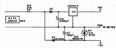
Fig. 7-2. Power supply.
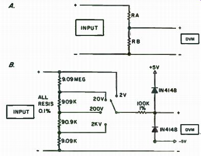
Fig. 7-3. Input attenuators, simple (a) and deluxe (b).
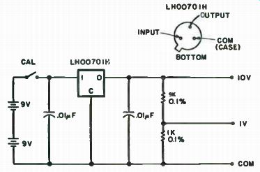
Fig. 7-4.
Calibration is quick and easy once you are set up. Obtain a DC voltmeter calibrator that is at least 0.01 percent accurate. Or, lacking that, you can build the calibrator shown in Fig. 7-4. It is designed around the National LH0070IH 0.01 percent 10 volt reference, which sells for about $5.00.
Circuit Specialists might be able to get one for you. Power is supplied by two 9 volt batteries. Lacking this calibrator, you can either calibrate your voltmeter against another DVM, OR (shudder) with a 1.34 volt mercury battery. The battery is a last resort, because you might be able to get only about 1 percent accuracy or so, depending upon the condition of the battery.
It should be fresh and unused.
With that out of the way, connect up the voltmeter and apply power.
Let it settle down for about 20 minutes or so and then short the input leads together. Adjust the zero pot, R2, for a 000 reading. You'll see the meter read something like 087-093-097-098-099-000-001-002 if all's well.
Once the zero is adjusted, apply either x2.000 volts from the commer cial calibrator (preferred) or + 1.000 volts from this calibrator. This is assuming you have the basic 0 to 2 volt unit; for other units increase the input voltage by x10, x 100 or whatever. Then tweak RI, the calibration pot, for a 1.999 to . 000 reading (or 1.000 with a 1 volt calibrator). Go back and short the input leads to check the zero; if it is necessary to adjust zero, recheck the calibration, too. These adjustments interact somewhat.
I hope you like your new digital voltmeter. It really adds a touch of class to have equipment in the workshop with digital readouts. The price is right, too. You probably spent about one-quarter as much for your meter as you would have for a commercial unit!
Build a 3 1/2 Digit DVM
If you have been looking for something to update your meter, but the price of a new one and the price of a portable digital voltmeter has scared you away, you'll love this project.
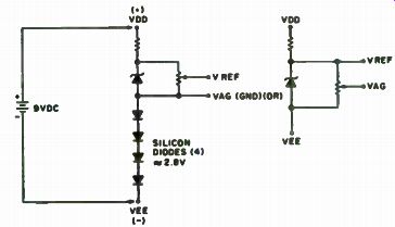
Fig. 7-5. This circuit is not. recommended for use with LED displays.
One of Motorola's new CMOS devices-the MC14433 -is an analog to-digital converter with a 3 1/2 digit display which can be set up for either a 200 mV or 2v full scale reading. The MC14433 is a high performance, low power 3 1/2 digit A/D converter combining both linear CMOS and digital CMOS circuits on a single monolithic IC. It is designed to minimize the use of external components, and with two external resistors and two external capacitors, the system forms a dual slope A/D converter with automatic zero correction and automatic polarity selection. For ease of use with batteries, the MC14433 may operate over a wide range of power supply voltages.
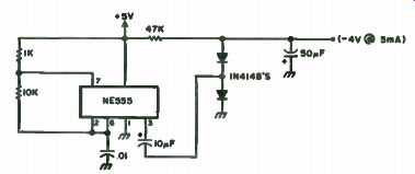
Fig. 7-6. Positive voltage to negative supply.
When you get one, make sure that it is on its own little piece of conductive foam, and don't take it off until you are ready to put it on the circuit perfboard.
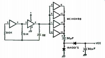
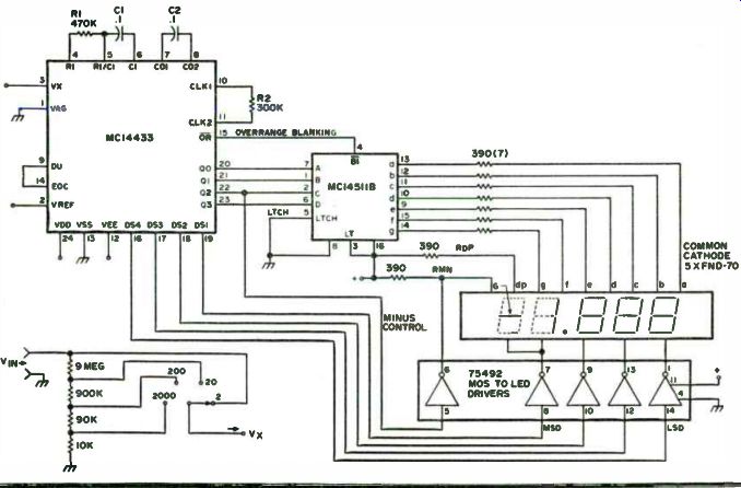
Fig. 7-8. For discrete LEDs, parallel all segments, but connect only segments
B and C to MD ( 1). When using 5 display units, tie the cathode of MSD and
the minus display unit together. For 2 V full scale: R1 = 470K, Vref = 2 V.
For 200 mV full scale: R1 = 270, Vref-200 mV.
This project is really a bare-bones layout with a minimum amount of functions, but all that is required to upgrade to a full function DVM is a few more resistors and switches. Since the MC14433 requires both a positive and a negative supply, it necessitates either the use of two batteries, or some other way to generate a negative voltage from a positive source. This is really quite easy and there are a couple of different methods to obtain it.
One easy way to get it is by the method shown in Fig. 7-5. In this example, a 9 volt supply can be used, with 3v between Vag and Vee, leaving 6v for Vac' to Vag. This system leaves a comfortable margin or battery degeneration (end of life). Note that due to the current requirements of the LEDs, this method is recommended for use only with LCDs. Another method is shown in Fig. 7-6.
This method uses the old reliable NE555. Since this thing generates a square wave, why not use only the negative cycle? Looking at the circuit in Fig. 7-7, we see that the 555 is connected in a regular oscillator fashion. The ...
Fig.
7-7. Another method of obtaining a negative supply form a positive supply.
When only + volts is available, a negative supply voltage can be generated
with this circuit. Two inverters from CMOS hex inverter are used as an oscillator,
with the remaining inverters used as buffers for higher current output. This
square wave output from the oscillator is level-translated into a negative-going
signal. This signal is rectified and filtered. A voltage of +5 V will result
in a -4.3V output.
... output, pin 3, is fed through a capacitor to the junction of two diodes. Dl allows the negative cycle to pass through it, and D2 allows the positive cycle to go through it to ground. After filtering, this negative wave is amazingly transformed into DC! An idea for saving money is to use potentiometers in the area of precision resistors on the input circuitry. Sure, precision resistors would be the way to go, but as long as we are being cheap about this thing, let's go all the way. There are definite values of resistors required for proper operation of the input circuitry, but instead of trying to find the closest thing in your junk box and hoping for the best, we will start with a value less than what is required and supplement it with a miniature 10 turn pot, which on the surplus market is relatively inexpensive. That way, you will have an even more precise resistor combination than you could get by ordering it.
Although a DVM can be made on a printed circuit board, a perfboard with sockets will do just fine, as parts layout is not really critical. One precaution, though: Try to keep wires away from the clock resistor and wave-forming circuits. Unlike with TTL devices, one cannot leave unconnected leads unconnected. Due to the extremely high impedance of these CMOS devices, you must tie the unused leads to a high or to a low. This circuit can be used with LEDs or LCDs with some changes, but in the interest of the local economy (your wallet), go with the popular FND-70 common cathode LEDs.
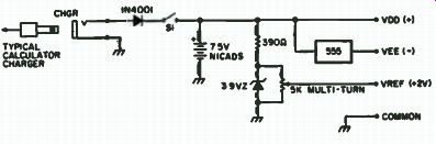
Fig. 7-9. Voltage chart. Total power requirements are approximately 60-70
mA.
Printed Circuit Boards. More should be about printed circuit boards.
Double-sided PC boards with plated-through holes are available, and the price will be in the vicinity of $4.00 to $6.00. This board has provisions for a few more frills and the price of a kit using that board sells for $39.95. Write for details to Dacron, Inc., 12609 Blackfoot Trail, Round Rock, TX 78664.
Calibration. The first thing to do in the way of calibration is to set the 200 mV reference voltage (or 2 volts, depending on which option you take). Do this with any accurate meter or another DVM, as the accuracy of the DVM depends upon this setting. Next, with an ohmmeter, set the value of your resistor strings to equal the required resistance, e.g., 5 megohms with a 5 meg pot for the required 9 megohms. Do this with all the resistors. When you have adjusted these to their approximate value, insert them into the circuit. Now you can fine tune the pots to the exact value. Note that when you adjust one pot, it will affect the values of the other ranges. This may take a while, but when it is complete, you will have a very accurate voltmeter.
Operation. This is the easiest of all. All that is required is that you feed it the voltage commensurate with the range it is in. While other common voltmeters can take a few "prangs" with the meter movement, do not try to measure 150 volts with the switch in the 2 volt range, for if you do, you will find yourself ordering another MC14433. The schematic and voltage chart for this project are found in Figs. 7-8 and 7-9.
Super DVM with LCD
If you are not only interested in replacing your old reliable Simpson 260, but are also interested in knowing what makes those funny liquid crystal displays work, your next voltmeter should contain only devices which won't suck up all the juice out of the batteries. Before we get into the actual circuit construction, let's start from the top with design theory.
The Display. The operation of a field effect liquid crystal display depends on changing the optical properties of a liquid crystal by applying an electric field. The best short description of a liquid crystal is that it is an ordered fluid.
Crystals of this type (liquid) which are used in displays belong to a class called nematic. Fluids of this type consist of cigar-shaped organic molecules with the long axis of each molecule pointing in the same direction. There are three main types of chemicals which are used in displays. These are Schiff bases, esters and & phenyls. At the present time, the Schiff-bases are the best choice for displays, taking into consideration switching times, reasonable threshold voltages, lifetimes, good temperature ranges and expense.
The Motorola MLC 400 is constructed from two pieces of glass coated with transparent indium oxide conductors. These conductors are shaped to form the segments of a numeric display. The glass surfaces are also specially treated to align the liquid crystal molecules in a particular direction. Alignment is parallel to the plane of the glass, with the alignment direction of the top rotated 90° relative to the alignment of the bottom plate. This causes the liquid crystal molecules in the cell to assume a twisted orientation, when viewed from top to bottom. The plane of polarization of plane-polarized light will follow this twist and emerge from the cell rotated 90°. Thus, if the cell is placed between crossed polarizers, the polarizers will transmit light. Where an electric field is applied, the liquid crystal will align parallel to the field, twist will be destroyed and that portion of the cell will appear dark between crossed polarizers.
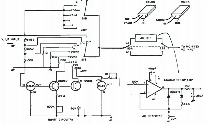
Fig. 7-10. Circuitry.
The MC14433. The MC14433 is a high performance, low power, 3 1/2 digit A/D converter combining both linear CMOS and digital CMOS circuits on a single monolithic IC. The chip is designed to minimize use of external resistors and two external resistors and two external capacitors, the system forms a dual slope A/D converter with automatic zero correction and automatic polarity. The MC14433 is ratio-metric, and, by itself, may be used over a full scale range from 199.9 millivolts to 1.999 volts. Systems using the MC14433 may operate over a wide range of power supply voltages for ease of use with batteries. In addition to DVM/DPM applications, the MC14433 ...
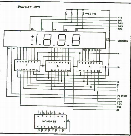
Fig. 7-11. Display unit.
... finds use in digital thermometers, digital scales, remote AID, AID control systems and MPU systems, and has an input impedance of greater than 1000 megohms! This A/D system performs a ratio-metric AID conversion. That is, the unknown input voltage, Vx, is measured as a ratio of the reference voltage, Vref. Therefore, a full scale voltage of 1.999v requires a reference voltage of 2.000v, while a full scale voltage of 199.9 mV requires a reference voltage of 200 mV. Both the Vx and Vref are high impedance inputs.
The circuit in Fig. 7-10 performs parameter-to-voltage conversions and scaling and function switching. The AC/DC DPST switch changes the input path and the signal is then fed into the MC14433. A 10 megohm voltage divider consisting of three precision resistors provides 2, 20 and 200 volt ranges. Three precision shunt resistors are connected directly from the input to ground, providing 1 A, 200 mA and 20 mA scales.
The resistance scales are established with calibrated current sources using the MC78L05 and MC79L05 voltage regulators. A stable 5 volts above the minus supply is produced by the 78L05 positive regulator. The current sources are simple base emitter biased transistors.
A 2N930 with a guaranteed beta at 1 microamp is used for the 2 megohm scale, and an MPS6513 is used as a 0.1 mA source for the 20k ohm scale.
Each is adjusted by a single 10-turn pot. The 200 ohm scale current source uses a 79L05 negative regulator. Its input is connected to the negative supply and a scaling resistor is placed between the common and output pins.
When not in use, this circuit draws only a few microamps of bias current, even though it sinks 10 mA when measuring a connected load. All current sources are biased from the minus supply to increase battery life; thus, all resistance scales produce a negative sign on the display.
When breadboarding the circuit, you could take the minus supply for the input circuitry from the common -6.2v bus. The only problem with this is that the 78 and 79L05 regulators require about 2 to 3 volts over the output voltage to work properly. Thus, the regulators will require at least 7 to 8 volts on the input to give 5 volts on the output. For this reason, it is recommended that you use 9 volt batteries. Note that absolute maximum voltages on the MC14433 are + and - 8v, so be sure to drop that portion of it somehow.
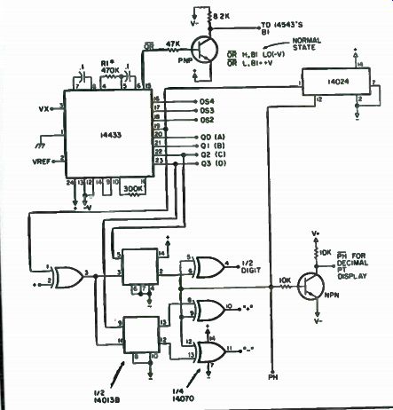
Fig. 7-12. For V full scale = 199.9 mV, set Vref = 200 mV and R1 to 27k. For
V full scale = 1.999 V, set Vref = 2 V and R1 to 470k.
The real substance of the project is shown in Figs. 7-11 and 7-12. Three MC14543N LCD latch/decoder drivers are used to de-multiplex, decode the
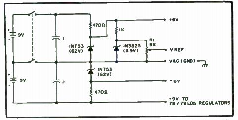
Fig. 7-13. Power distribution. Set R1 for an output voltage of 2 V. It must
be accurate and with load connected. Any zener diode of equivalent value may
be used.
three digits and drive the LCD. The half digit and polarity are de-multiplexed with the MC14013B dual D flip-flop. Since the LCD requires an AC signal across it, the low frequency square wave drive for the LCD is derived from the MC14024 binary counter, which divides the digit select output from the AID. Although this is a convenient way to obtain the required square wave, it is not necessary to take it from here. The frequency should be about 4 kHz, as this will provide for the best contrast on the display unit. This low frequency square wave is connected to the backplane of the LCD and to the individual segments through the combination of the output circuitry of the 543B and the exclusive OR gates at the outputs of the 013B. All of the decimal points are tied to PH through a 1 megohm resistor, and, to display a particular DP, it is switched to PH. The overrange pin ( 15) goes low when Vx exceeds Vref. It is normally high. The 543Bs require a ground on pins 7 (blanking) to display. In our case, the ground is actually the most negative supply (to get the maximum amount of voltage swing on the output). This normally high OR pin on the 433 is tied to a PNP transistor, which is tied between - V and +V. In its normal state, the transistor is not conducting, thus allowing the - V to be on the collector.
When the input goes low, indicating an overrange condition, the transistor conducts and places a high (+) on the blanking input of the 543s, thus blanking them. Note that the first digit has no provision for blanking.
You can wire-wrap the LCD socket and the 543Bs. One reason for this is because the pins of the socket of the LCD are very close together.
Calibration. The first thing to do in the way of calibration is to set the reference voltage. Note on the schematic that it can be set up for 2 volts or 200 mV full scale (Figs. 7-13, 7-14 and 7-15). It should be set for 2 volts due to possible noise problems, but, even with the 2 volt scale, it can be read to 0.001 volt. Be sure to be accurate with this reference voltage, as the accuracy of the entire instrument depends upon it. A short word should be said about the quality of components used in the frequency determining resistors and capacitors, especially in the capacitors. These 0.1 uF caps should be of the high quality polyester or mylar. Using cheap caps here can lead to inaccurate readings.
If you used precision resistors for the voltage divider network, the next step is to calibrate the ohms scales against known resistance values. Just tweak the control until the correct value is displayed. If you used pots in place of the precision resistors (in the interest of saving money), you must set these up. The way to do this is to get a calibrated voltage source. Set the voltmeter to the 200 volt range, and adjust the 100k pot for a correct reading on the meter with about 90 to 120 volts applied to the input. Watch out, as the 433 doesn't really like all that voltage, especially if it is applied directly to the 2v scale. It might blank out forever! After you have calibrated the 200 volt scale, don't touch that pot again. Apply about 16 volts to the input and adjust the 900k pot for a correct reading. Next, do the same thing for the 2 volt scale, using the appropriate voltages. After this, you will probably have to touch each of the pots up, as each will interact with the other. With a little time, you can save yourself a little money, and probably have a more accurate meter than if you were to buy precision resistors! There are a few things which you should be on guard for and those are in the area of the AC detector circuit. Since this is essentially an amplifier/ detector circuit, anything that is placed on the input will show up as a DC potential on the output. The Ac detector circuit takes more time to refine than does the rest of the DVOM. On the switch assembly, don't run the PH and PH lines with unshielded wire because the input is a very high impedance, and therefore doesn't take very much to drive it. So, a little shielding and careful placement should take care of it.
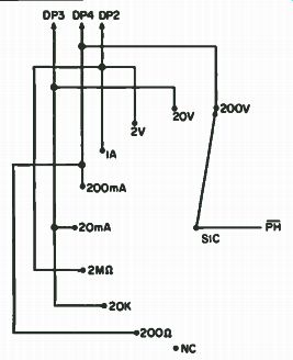
Fig. 7-14. Decimal point switching. To energize DP, tie line to PH.
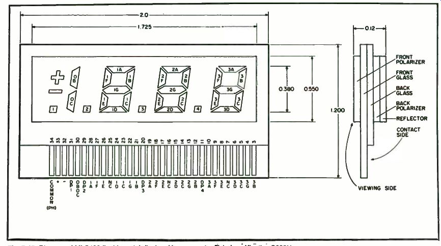
Fig. 7-15. Diagram of MLC400 liquid crystal display. Use connector Teledyne
Kinetics S202U.
To calibrate the AC scale, the easiest way is to set up the voltmeter to the 200 volt scale and measure the line voltage of your house. If it does not read correctly, turn the pot until it does.
Another little hint-be sure not to hook up the analog ground to chassis ground as if you are measuring current in a high voltage circuit. This will place a high potential on the bare metal chassis. The chip is available from Tri-Tek for $18.95.
PC boards for a basic 2v DVM using LEDs can be purchased from Dactron, Inc. 12609 Blackfoot Trail, Round Rock, TX 78664.
Ecstasy In Multi-meter-land with an Autoranging Marvel
The most frequently used and trusted piece of test gear is the VOM. New ICs have changed the appearance of the VOM by taking a giant step in providing numeric readouts in the place of the sometimes difficult-to-read meter movement. Even if the greater accuracy was not considered, the ability to match voltage currents and resistors was greatly improved. however, not until recently have the IC manufacturers been able to provide the function we have all been waiting for -autoranging! The operation, construction and calibration of a complete 4-3/4-digit autoranging, auto-zero, auto-polarity digital multimeter capable of measuring DC or AC volts (. 1 millivolt to 2. 9999kv), DC or AC current (1 uA to 2.9999 amps) and ohms (0.1 ohm to 29.999 megohms). The autoranging feature will automatically provide the proper decimal location to give the most significant digits possible. A single 5v supply is all that is needed for operation of the meter.
Circuit Description. The block diagram shows how simple the circuitry has become with the introduction of Intersir s 8052 analog signal conditioner and General Instrument's AY-3-3550 4-3/4-digit DMM integrated circuit.
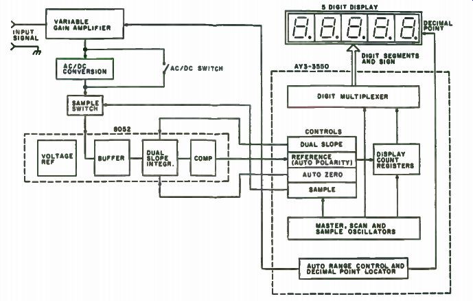
(Figs. 7-16 through 7-19). A voltage of unknown amplitude is applied to the variable gain amplifier.
Ideally, the output of the amplifier will be between +2v and - 2v. The output will be converted to DC if the AC/DC switch is in the AC mode. This unknown voltage will be applied to the input of the 8052 (IC11) only when the AY-3-3550 (IC3) is ready to make a measurement. When ready, the sample switch will be enabled for 10,000 counts, the sample switch is turned off, the comparator output is sensed for polarity by IC3 and the polarity data is used to force the dual slope integrator to integrate in the opposite direction. IC3 will store the count required for the integrator to cross zero. This count will be directly related to the amplitude of the unknown voltage. If the integrator does not reach Ov by 20,000 counts, the unknown voltage is too large. In this case, the variable gain amplifier is set to reduce the unknown voltage by a factor of 10 and start the sampling over again. If the count is less than 1800, then the variable gain amplifier has insufficient gain. In this case, the gain will be increased by 10, and the sampling will repeat. Note that as the gain is changed, the decimal point is shifted.
Between voltage samples, the autozero circuit of IC3 will recalibrate specific capacitors so that the new measurement will start from zero.
Fig. 7-16. Autoranging DMM block diagram.
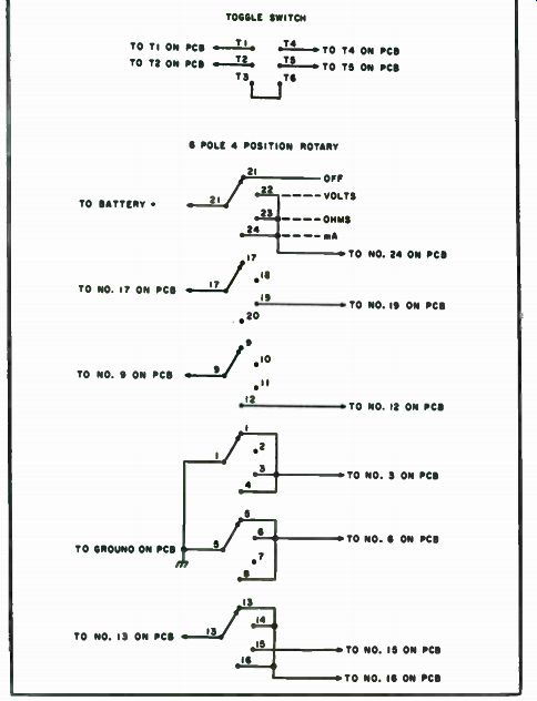
Fig. 7-17. Switch wiring diagram.
The 5-digit display is controlled by the digit multiplexer internal to IC3.
An LED to the immediate left of the display is on for negative measure ments.
The circuitry is complicated by the requirement of an accurate positive and negative voltage reference for dual-slope integration. A "flying capacitor" technique is used to bias all input voltage to IC11 to + 1 volt. This way, a ground level appears to be - 1 volt, and only a positive reference is required.
Another complication is that IC3 does not have the drive capability for the numeric readouts. Therefore, a 7447 decoder driver must be added for segment and discrete transistors must be used for digit drivers. Resistors are required to limit base currents and additional resistors are required to limit segment current.
In order to control the variable gain amplifier, sample switch and autozero circuit, analog switches must be used. The three analog switch packages are powered from a ±- 8.2v supply. The control input to these switches must also be ±8.2v. Therefore, a level converter is necessary to convert the +5 ground level of IC3 to ±8.2v. The three LM339 ICs were added for this purpose. Leftover portions of the LM339s were used for gating functions.
IC3 has inputs which provide the capability of changing the upper and lower limits of the auto-range circuitry. Since all three functions use different limits, a 4052 (IC4) multiplexer was required. IC4 senses the mode of operation and applies the desired range limits to IC3. For example, the upper range for volts in nnnn.n and the upper range for ohms is nn.nnn.
The ±8.2volt supply was developed experimentally. A 555 (IC7) oscillator drives the primacy of a transformer. Each side of the center-tapped secondary forms a half-wave recitifier circuit with one being positive and the other being negative. Each voltage is regulated at 8.2 volts to limit the maximum output voltage.
Since IC3 is a digital multimeter, not a digital voltmeter, use of existing circuitry to measure resistance and current is simplified. In addition to providing two inputs to IC3 for the function desired, slight modification to the variable gain amplifier is required. When reading ohms, the unknown resistor becomes the feedback resistor for IC12, and the feedback resistors become the input resistors for IC12. Current measurement is made possible by measuring the voltage drops across a 1-ohm resistor.
Construction. The use of a double-sided plated-through printed circuit board simplified construction. For a complete parts list, see Table 7-2.
The most important decision, prior to inserting parts as shown on the assembly drawing (Fig. 7-20), is to consider the mounting of the PC board.
The front panel is 3/4 " from the board. It was with this in mind that most capacitors were mounted on the bottom side. The transformer also presents a problem and is mounted on the bottom.
The four 18-turn pots can be mounted on the bottom. This will permit calibration without removing the front panel.
The rotary switch must be insulated from the board using nonconducting washers.
Do not remove the nut on the switch; doing so can change the stop pin for the switch. Wiring from the switch to the PCB is simple, since the points on the board contain the same number as the points on the switch. The common lugs are slightly recessed. When wiring to a common lug, go to the number specified and use the recessed lug (the one closest to the shaft). Switch lug-to-switch lug wiring should be done according to the switch wiring diagram (Fig. 7-17). The AC/DC toggle switch should be wired as shown in Fig. 7-17. The PCB is marked for easy switch-to-PCB wiring. Be careful when installing this switch in the panel as it is easy to put it in upside down.
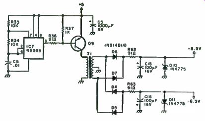
Fig. 7-18. +8.2-volt supply.
Use caution when inserting the ICs. Note that pin 1 is located away from the NRO, except for IC4 and IC5.
T1 wiring is aided by PCB marking. The white, black and yellow leads are dosest to the NRO. Only the yellow and white leads are used (marked Y and W). The white, blue and red leads are connected to the W, B and R points marked on the PCB. Calibration. The most critical adjustment is R40-the 1.0000-volt reference. This is the one calibration point where it is desirable to borrow an extremely accurate voltmeter. An easy point to pick up this line is switch 2 lug 15. Simply adjust R40 until a 1.0000-volt reading is measured. With the DMM in the volts mode; short the voltage input to ground and adjust R48 for a zero reading on the DMM display.
Connect a known-value AC voltage to the voltage input, and adjust R50 for a proper reading on the DMM display. Make sure the AC/DC switch is in the AC position. Insert a 1k to 1.799k precision resistor across the ohms input (AC/DC switch in DC position), and adjust R39 so that the DMM display gives the correct value for the resistor.
If an accurate voltmeter cannot be obtained, then calibration can be accomplished by the following procedure:
• Short out the voltage input leads, set the meter to DC volts and adjust R48 for a zero reading.
• Obtain a precision resistor above 1800 ohms (10k to 17.9k desirable), set the meter to the ohms mode and connect the resistor to the meter leads. Adjust R40 until the DMM gives the proper value.
• Obtain a precision resistor below 1800 ohms (1k to 1.79k desirable), set the meter to the ohms mode and connect the resistor to the meter leads. Adjust R3 until the DMM gives the proper value.
• Set the DMM to read AC volts. Connect the voltage probe to SW2 pin 15 and adjust R50 until the DMM reads 1.0000 volts.
-----------------
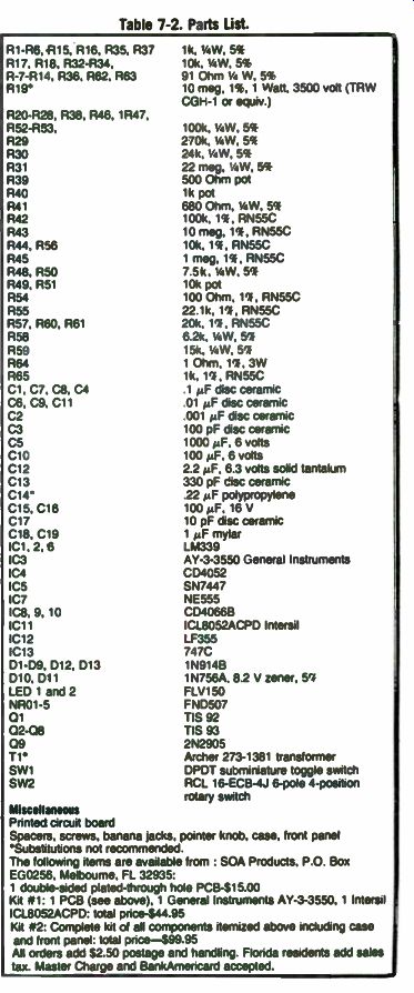
Table 7-2. Parts List.
R1- R6, R15, R16, R35, R37 R17 Ri8, R32-R34 R-7-R14, R36, R62, R63 R19* 1k, 1/4 W, 5% 10k, 1/4 W, 5% 91 Ohm 1/4 W, 5% 10 meg, 1%, 1 Watt. 3500 volt ( TRW CGH-1 or equiv ) P20-P28, R38. R46, 1R47, R52-R53, 100k, UW, 5% R29 270k, 1/4 W, 5% R30 24k, 1/4 W, 5% R31 22 meg, 1/4 W, 5% R39 500 Ohm pot R40 1k pot R41 680 Ohm, 1/4 W, 5% R42 100k, 1%, RN55C R43 10 meg, 1%, RN55C R44, R56 10k, 1%, RN55C R45 1 meg, 1%, RN55C R48, R50 7.5k, UW, 5% R49, R51 10k pot R54 100 Ohm, 1%, RN55C R55 22.1k, 1%, RN55C R57. R60, R61 20k, 1%, RN55C R58 6.2k, 1/4 W, 5% R59 15k, 1/4 W, 5% R64 1 Ohm, 1%, 3W R65 1k, 1%, RN55C C1, C7, C8, C4 1 µF disc ceramic C6, C9 C11 01 µF disc ceramic C2 001 µF disc ceramic C3 100 pF disc ceramic C5 1000 MF, 6 volts C10 100 µF, 6 volts C12 2.2 µF, 6.3 volts solid tantalum C13 330 pF disc ceramic C14* .22 MF polypropylene C15. C16 100 µF, 16 V C17 10 pF disc ceramic C18, C19 1 MF mylar IC1, 2,6 LM339 IC3 AY-3-3550 General Instruments IC4 CD4052 IC5 SN7447 IC7 NE555 IC8, 9, 10 C040666 IC11 ICL8052ACPD Intersil IC12 LF355 IC13 747C D1- D9, 012, 013 1N914B D10. D11 1N756A, 8.2 V zener, 5% LED 1 and 2 FLV150 NR01-5 FND507
01 TIS 92
02-08 TIS 93
09 2N2905 T1 Archer 273-1381 transformer SW1 DPDT subminiature toggle switch SW2 RCL 16-ECB-4J 6- pole 4- position rotary switch
Miscellaneous
Printed circuit board
Spacers, screws, banana jacks, pointer knob, case, front panel
'Substitutions not recommended.
The following items are available from : SOA Products. P.O. Box EG0256, Melbourne, FL 32935: 1 double-sided plated- through hole PCB-515.00 Kit # 1: 1 PCB (see above), 1 General Instruments AY-3-3550, 1 Intersil ICL8052ACPD. total price-$44.95 Kit 42: Complete kit of all components itemized above including case and front panel total price-$99.95 All orders add $2.50 postage and handling. Florida residents add sales tax. Master Charge and BankAmericard accepted.
-----------------------------
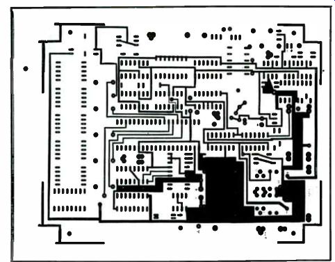
Fig. 7-19. PC board.
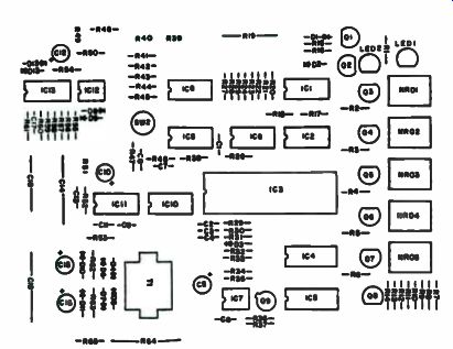
Fig. 7-20. Component layout.
Operation. The actual operation of the DMM is relatively easy. To measure voltage, move the function switch to VOLTS, and insert the meter leads in COM and VOLTS. The reading you get will always be in volts. To measure current, select the mA function and insert the meter leads in MA and COM. All measurements will be in mA. To measure ohms, select the ohms function and insert the meter leads in OHMS-C and OHMS. All measurements made without the MOHMS indicator on will be in kilohms. If the MOHMS indicator is on the reading is in megohms.
--
Next: Calibrators and Frequency Standards