Inexpensive HF- VHF Frequency Standard
There have been many frequency standard projects published in books in recent years using advanced technology integrated circuits, however, there is a need for a foolproof circuit that is both inexpensive and easy to build in a modest workshop. Most projects neglect the need for 30 kHz and 300 kHz markers in VHF FM operations, where 30 kHz is the standard channel spacing. Also, most 2m FM frequency standards neglect the needed 100 kHz and 10 kHz markers are used by the HF man. This prompted an interest for a simple design frequency standard which could develop both 30 kHz and 10 kHz markers as well as a host of other frequencies.
This standard uses readily available TTL integrated circuits.
The integrated circuits should not cost more than $4.50 total. You may have a crystal in your junk box, but an International EX Crystal should work as well. It costs $4.95.
The block diagram of the frequency standard is shown in Fig. 8-1. Note that a 5 volt regulator was used to furnish the 5 volts needed by the TTL circuits. By using a regulator, an automobile 12 volt battery can be used to power the frequency standard when tuning up the mobile rig in the car. Also, a lantern battery may be used to power the unit for portable use as on field day. The 9 Mhz oscillator is composed of a hex inverter operating in the linear mode. The 9 MHz output from the oscillator is divided by three to generate the 3 MHz signal used by the rest of the circuit. Two divide-by-ten circuits are then used to generate the 300 kHz and 30 kHz marker outputs.
When 100 kHz outputs are required, another divide-by-three circuit is inserted between the 3 MHz signal and the divide-by-tens. Since there are two different outputs on each BNC connector, a small LED is used to signal when the second divide-by-three is in the circuit. The LED monitors the output of the divide-by-three and when it is outputting, the LED is illuminated corresponding to 1 MHz, 100 kHz or 10 kHz selections. When the LED is not illuminated, then the outputs are 3 MHz, 300 kHz or 30 kHz.
The circuit diagram of the frequency standard is shown in Fig. 8-2. A 7404 TTL hex inverted is used as the crystal oscillator. A small 2-8 pF trimmer capacitor is used to permit zeroing the crystal with WWV. A 7476 TTL dual J-K flip-flop is connected in a standard divide-by-three configuration. This same circuit is used later as the divide-by-three in order to...
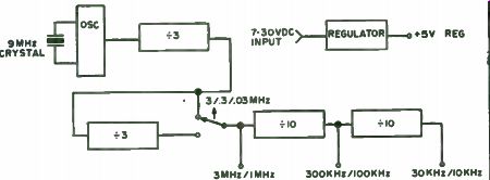
Fig. 8-1. Block diagram of the frequency standard. Selection of the 1 MHz/.1
MHz/.1 MHz is made by the toggle switch.
...produce the 100 kHz markers. A toggle switch selects either the second divide-by-three or bypasses it depending whether 100 kHz markers are needed. Two 7490 TTL decade dividers are then used to furnish the lower frequency markers.
The TTL circuit layout is not critical. The standard, however, should be built close together to keep down stray capacitances. To help those who wish to duplicate the circuit, circuit boards are being made available. Alter natively, the circuit may be built on a small vector board. Sockets may be used to help in the point-to-point wiring.
The board was mounted in a small aluminum box and BNC connectors were used for the outputs. The frequency standard is quite readable at 150 MHz and probably higher. Because of the square wave output, the harmonic content is very high. To calibrate the oscillator, the 100 kHz mode is chosen.
The 100 kHz is then compared with WWV at 5, 10 or 15 MHz. The small trimmer capacitor is then adjusted until a zero beat is noted. Using this method, the harmonics at 146 MHz should be no more than a few Hz off.
The World's Cheapest Calibrator Even Works on 2M!
Having trouble netting your transmit crystals on your 2 meter handie-talkie or transceiver? Can't buy or conveniently borrow a frequency counter to do the job? With today's proliferation of sensitive, narrow band repeaters, it is increasingly important to be right on frequency to obtain maximum range and good audio quality from your own gear when "making the system." Even when operating simplex the tolerant wide band receivers are rapidly disappearing. Most would agree equipment should be within about - 1-1 kHz of the nominal channel frequency for optimum results.
You may be tired of borrowing a frequency counter every time you put new rocks in your equipment or change the channel locations of some of them and can't see putting out $ 100 or more for a frequency counter. How about adding a 2 meter converter to your low band receiver with its stable 1 kHz calibration? So what if the low band receiver is for SSB-CW and your 2 meter gear is FM. The frequency of the unmodulated FM carrier would be just as recognizable as a continuous CW signal.
In looking around for a 2 meter converter for your receiver if it should happen to be a HeathIçit SB-301 low band receiver, you'll discover Heath Company no longer makes the Model SBA-300-4 2 meter converter. however, you can pick up a used one in a flea market for about $ 10.! The Heath Model SBA-300-4 2 meter converter output is a 28-30 MHz signal that is inputted into the four SB-301 half megahertz 10 meter band increments.
With the proper crystal in the converter, any 2 MHz segment of 2 meters is tunable with 1 kHz resolution on the SB-301. Other 2 meter converters are available or you can build one yourself.
Netting 2 meter crystals is a snap now. First, check the calibration of your receiver and converter. You can verify it by comparing it to the output frequency of one or more of the accurately calibrated repeater stations when keyed by an unmodulated FM carrier with the receiver in the CW position.
Use a minimal antenna or back off the rf gain if necessary, so your receiver is not overloaded and the S-meter reaches a maximum without pinning the needle. Reset your receiver dial hairline if required for accurate calibration.
The actual netting of your 2 meter crystals is simple. Feed your transceiver, preferably into a dummy load. Turn your low band receiver sudio gain down to minimum to prevent audio feedback. Use little or no receiver antenna or reduce rf gain if necessary to avoid overloading. With the low band converted receiver set to the desired 2 meter frequency, adjust the netting capacitor for maximum S-meter reading by alternately keying and adjusting the 2 meter gear. Double check your work by varying the receiver frequency slightly while keying your unmodulated 2 meter...
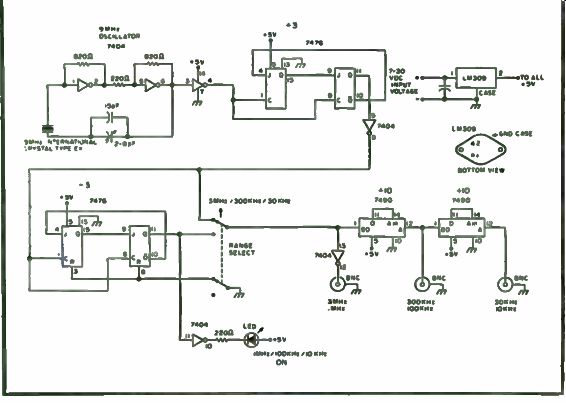
Fig. 8-2. Schematic of the inexpensive frequency standard using readily available
parts.
...transceiver. The S-meter reading should peak sharply at the desired frequency, especially with the receiver in the CW mode.
You can get to within about ±1 kHz using this-and for $ 10 that's a good bargain! As a bonus, a low band receiver-converter can be used to receive FM (somewhat poorly though) in an emergency by detecting it off the bandpass slope in the low band receiver.
All Band Frequency Muter
Crystal controlled marker generators are useful adjuncts in any frequency determining situation requiring high accuracy, such as locating band edges, sub-bands and calibrating receivers. If you've been entertaining thoughts about construction of one, a version is described here which uses the new C/MOS integrated circuits powered by a 9 volt transistor radio battery. And instead of the usual rotary harmonic selector switch, a multipin IC connector strip and three test plugs serve as a miniature patch panel to enable various divisions of the reference crystal, with a maximum countdown of 256. Rocks from 100 kHz to 4 MHz oscillate readily in this circuit. In this model an FT241 xtal set to 400,000 Hz has been chosen for control and has usable receiver calibration divisions down to 2.5 kHz. The harmonic spectrum extends to at least 160 MHz, the tuning limit of a transistor superregen used in testing. When used in densely occupied HF bands, an AM beeper can be switched on as an identification aid.
Referring to Fig. 8-3, one third of a hex inverter makes up a crystal controlled oscillator and buffer, another third is a slow rate pulser and the two remaining units function in the dividing section. These are all standard circuits described in RCA's COS/MOS Data Book #SSD-203. An emitter follower minimizes loading on the IC outputs, speeds up rise time to increase harmonic content and provides a low impedance output. The AM beeper is a simple clamp that gates rf on or off to following stages. A complete parts list can be found in Table 8-1.
All components are mounted on Vector P pattern perfboard that fits inside a Bud mini box. Sleeving 3/8” ( 10mm) long is slipped over the wire trap terminals of the contact strip to space it up from the board. A DPDT center-off miniature toggle switch acts as one board to panel spacer.
Diagonally across from it, a 4-40 threaded rod conducts emitter follower output up through the front panel via a 1/2 " (13mm) insulating spacer and plastic shoulder washers.Two regular 4-40 screws and spacers complete the four corner mounting. This spacing allows the contact strip to project partly through a panel cutout so that it is mechanically secure without fastening.
The completed assembly has a stick-on label with patching connection callouts for various division ratios. If only one crystal is employed, labeling could indicate most used frequencies instead. A typical frequency vs. division listing for this model is shown in Table 8-2. You can easily make up a complete table of all possible ratios, remembering that each CD4015 shift register divides by even numbers only, starting at 2 and ending at 16.
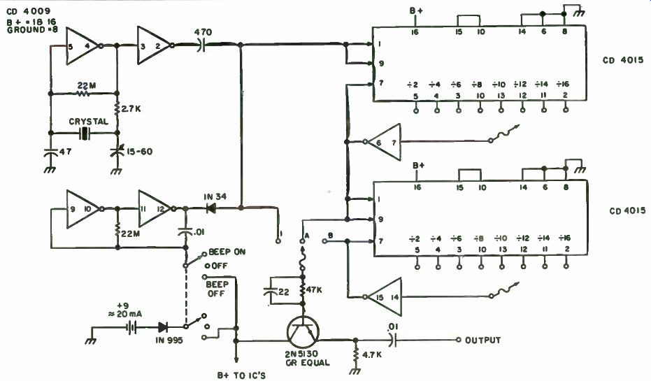
Fig. 8-3. Schematic.
---------------------
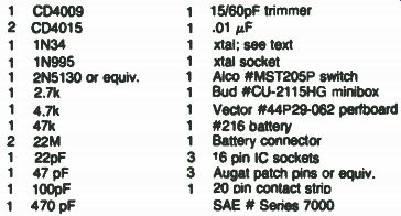
Table 8-1. Parts List
1 CD4009 2 CD4015 1 1N34 1 1N995 1 2N5130 or equiv.
1 2.7k 1 4.7k 1 47k 2 22M 1 22pF 1 47 pF 1 100pF 1 470 pF 1 15/60pF trimmer 1 .01 uF 1 xtal; see text 1 xtal socket 1 Alco #MST205P switch
1 Bud #CU-2115HG minibox
1 Vector #44P29-062 pert board
1 #216 battery
1 Battery connector
3 16 pin IC sockets
3 Augat patch pins or equiv.
1 20 Din contact strio SAE # Sedes 7000
-------------------------
Uses to which a marker generator may be put have been described before: i-f alignment, BFO, scope linearity, etc. A type that divides down to the audio range like this one is especially useful in checking superhets. A very broad and flat spectrum of overlapping signals is generated and an audio tone will be heard no matter where the set is tuned. If its tracking and sensitivity are top-notch, the S meter will hold steady over the tuning range.
Tracking adjustment amounts to tweaking for maximum meter reading or loudest audio tone. Then patch for 100 KHz markers and check calibration.
It's a lot faster and easier than using a conventional signal generator.
A Synthesized IC Frequency Standard
Synthesized receivers are gradually appearing in the marketplace.
Their numbers will increase as the cost of complex ICs drops. They all operate basically the same, using the phase lock loop (PLL) technique of generating L. O (local oscillator) frequencies. One crystal i used to generate the whole range of L.O. frequencies- each frequency as accurate as the crystal.
Here's a project that will provide you with several precise (0.005 percent) frequency standards and also get you familiar with phase lock loops.
The heart of this unit is the NE562 phase lock loop. Internally it has a phase comparator, adjustable low pass filter, a VCO (voltage controlled oscillator) and two outputs. It also has provisions for inserting a programmable divider between the phrase comparator and VCO, thus permitting frequencies to be changed.
The frequency range of this device is 1 to 10 MHz in 1 MHz steps, with an accuracy of . 005 percent at each frequency (greater accuracy is possible with a closer tolerance xtal). The output is a symmetrical square wave at each frequency that is useful as a scope timebase calibrator, checking bandwidth and frequency response of HF amplifiers, calibrating communication receivers with the 100 kHz output or as a "clock" for future IC projects.
All of the ICs (including the NE562) are readily available from electronic mail order houses. The remaining few parts you can get from your junkbox.
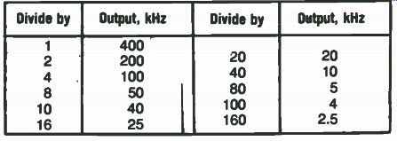
Table 8-2. Frequency vs. Division Listing.
How It Works. Before we get into the details of construction, a little basic operation of phase lock loops may be helpful. A basic phase lock loop consists of a phase comparator, a VCO and a low pass filter, as shown in Fig. 8-4.
The phase comparator (or phase detector) has two inputs-the reference frequency and the output of the VCO. The output of the phase comparator is a DC control voltage proportional to the phase difference between the two input frequencies. The control voltage equation is:
Vc = K (() ref-Ovco)
... where K is a constant in volts/radian and (Oref-Ovco) is the phase difference in radians. Now the VCO frequency is controlled by a DC voltage. As the frequency of the VCO tends to drift, a phase error develops and is fed back to the comparator which compares it with the reference signal and produces a DC voltage that changes the frequency of the VCO in the direction that will reduce the phase error. Since the VCO is controlled by a DC voltage, any ripple on the voltage will FM (frequency modulate) the VCO. That's the purpose of the low pass filter between the phase com parator and VCO, to reduce this ripple. It also helps to set the capture range of the loop.
One drawback of Fig. 8-4 is that it will only work at one frequency. The output frequency is the same as the reference and there is no way to change the frequency. If we put a variable divider (+ N) between the VCO and the phase comparator feedback path, we can vary the frequency of the VCO, then divide it down so that the phase comparator inputs are always the same.
This allows us to change the VCO yet maintain the same inputs to the phase comparator (Fig. 8-5). The control voltage equation now is:
V = K Eref-Ovc] c N
... where N is the number programmed into the variable divider. The operation of this system is the same as the basic loop just described.
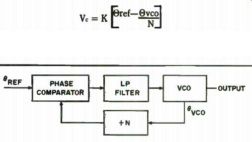
Fig. 8-4. Basic phase lock loop.
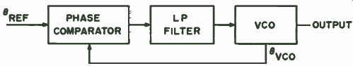
Fig. 8-5. Variable divider added to basic phase lock loop.
The Reference Circuitry. The circuitry (Figs. 8-6 and 8-7) of Q1 is a 10 MHz . 005 percent crystal controlled oscillator. R2 and R3 is the bias network. C12 is the feedback capacitor and is part of the resonant tank along with C13 and L1. If you don't have a 0.7 uH inductor for L1, you can make your own by winding 19 turns of #30 magnet wire (closewound) on a 1/2 watt resistor (100k or larger). C13 is 2 680 pF capacitors in parallel. X1 is a 10 MHz . 005 percent (series resonant) crystal.
C25 is a coupling capacitor to the following IC. Normally, a shaping circuit would be included here. But the rise and fall times at 10 MHz are adequate to trigger the IC. We will need a diode though (CR1) to clip the negative going transitions and prevent Veb breakdown in the IC, IC1, IC2 and IC3 are wired to divide by 10. The output of IC3 is at 10 kHz. This will be the reference signal for the phase comparator. You'll note that IC3 is wired a little differently than IC1 and IC2. This is done so that a symmetrical 10 ld-lz square wave is fed to the comparator. R5 reduces the drive level into the comparator.
The Programmable Divider Circuitry. Pin 4 on IC4 is one of the VCO outputs. R10, R11 and C20 couple the signal out while still maintaining a DC path for the emitter in IC4. This signal is fed into IC9 which is V2 of an SN7413. The SN7413 is a dual Schmitt trigger. A Schmitt trigger improves the rise and fall transitions over a wide range of input frequencies. Since the output frequency changes from 1 to 10 MHz, suitable transitions are necessary over the full range of frequencies to insure positive triggering for the following IC. IC7 is a prescaler. It divides the output of the VCO by 10. This was done so that the programmable divider following (IC6) will operate at a lower range of frequencies, from 100 kHz to 1 MHz. Propagation delays and race conditions can cause false triggering at high frequencies. IC6 is the programmable divider. This is where all the switching of the system takes place. Basically, we want to divide all frequencies out of the VCO so that the output of the programmable divider is always 100 kHz. For example, if the VCO is at 5 MHz, the prescaler reduces it to 500 kHz and the programmable divider is switched to +5 and the output is 100 kHz. If the VCO is at 9 MHz, the programmable divider is switched to + 9 and the output is 100 kHz. IC6 can be switched from +2 to + 9. Now at 1 MHz the output of the prescaler is 100 kHz. We don't need the programmable divider here so it is simply bypassed. The output of IC6 is further divided by 10 in IC5, wired to provide a symmetrical 10 kHz square wave out. R12 is the same as R5, to reduce the drive to the phase comparator. R15, CR2 and CR3 are part of the +7 decoding. CR2 and CR3 can be any general purpose germanium diodes. IC8 inverts the A, B, C, D outputs of IC6 to provide the A, B, C, D, outputs to decode the programmable divider.
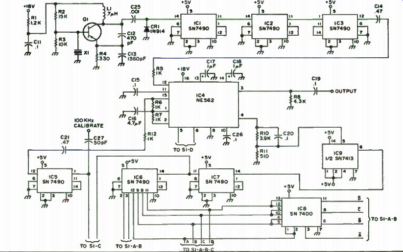
Fig. 8-6. Schematic diagram. R1-R12-1/4 Watt carbon resistors; C11, C15, C19,
C20, C25, C26-20 V disc; C12-silver mica Elmenco DM19; C13-silver mica (2-680
pF in parallel) DM 19; C14, C21-35 V Sprague type 196D, 474X0035HAI; C17, C18-35
V Sprague type 196D, 105X0035HAI; ICI, IC2, IC3,1C5, IC6, 1C7-SN7490 decade
counter; 1C4-NE562 phase lock loop;IC8-SN7400 NAND gate; IC9-SN7413 NAND Schmitt
trigger; Q1-2N5172;X1-10MHz .005% crystal (series reasonant) from Jan Crystals,
2400 Crystal Dr., Ft. Myers FL 33901; L1-.7 microhenry inductor; S1-rotary
switch 4 pole 10 position, Centralab PA- 1015.
Fig. 8-7. Power supply. R13, R14-carbon resistors; C22-15V; C23, C24-50 V; T1-12.6 V rms power xfmr Allied 6K36HF; Z1-1-5% zener diode 1N4733A; CR4-CR7-1N4002 (PRV 100 V, 1A).
So now we have described the development of the two input signals to the phase comparator, one signal a fixed reference (Oref) and the other containing the phase error information (Ovco) from the VCO. Pins 5 and 6 on the NE562 (IC4) are provided for capacity tuning the VCO. As each frequency is switched, the capacitor across pins 5 and 6 has to be switched. The free running frequency of the VCO has to be tuned within the capture range of the loop. As mentioned earlier, the low pass filter determines the capture range of the loop. C17 and C18 on pins 13 and 14, respectively, on IC4 are the low pass filter capacitors. When the free running VCO is tuned within approximately 300 kHz of center frequency, the loop will lock. Table 8-3 gives the approximate tuning capacitors for Fc at each frequency. They should all be silver mica (Fig. 8-8). Construction. Except for the power supply and divider-frequency switch, all the parts are mounted on the 3-7/16" x 5" etched PC board (Fig. 8-9). Holes are provided on the board for all the wires going to S1. Sockets can be used for all the ICs to simplify troubleshooting, if necessary, or they can be hard wired to the board. Molex terminals are available at electronic stores and work well here.
They're inexpensive and are satisfactory sockets. Holes are also provided to strap all the IC power connections. Use magnet wire. Several circuit jumpers are also needed as shown on the parts layout of Fig. 8-10.
C1- C10 should be mounted right on the switch (S1), with all the common points brought together in the center. Run a wire to the circuit board.
Final Checkout. Before applying power, check that all the jumpers are in and the ICs are mounted in the correct positions. Set the frequency switch to the 1 MHz position. After you're sure everything is fine, apply power and check that the supply voltages are present. + 18 volts should be at the junction of R14 and C24. R14 can be changed to make it + 18 volts. + 5 volts should be at the zener diode. A counter would come in handy here for the following check but a scope will do. A triggered scope is even better. At the junction of C14 and R5, there should be a 10 kHz square wave approximately 3 volts peak to peak. This one point checks that the oscillator is working and also the divider chain. The same wave shape should be at the junction of C21, R12. If it is, the loop is locked at 1 MHz 0.005 percent. Repeat this for each position of the frequency switch. If you reach a position where both wave shapes are not the same, check the switch wiring of the programmable divider. If it's alright, you'll have to adjust the tuning capacitor for that particular channel. Calibrate the scope using the reference 10 kHz signal.
Display one square wave for 10 cm on the scope (junction C14, R5). Move the probe to the junction of C21, R12 and adjust the tuning capacitor until the same wave shape appears.
If the output is to be used as a "clock" to drive TTL circuitry, the circuit in Fig. 8-11 is suggested.
Use low capacity cabling on the output if you're going to run it any distance to preserve the wave shape. With the front panel switch in the 2 MHz position, a symmetrical 100 kHz signal is available on the front panel for calibrating communication receivers; simply couple the output (loosely) to the antenna input. A miscellaneous parts list for this project is found in Table 8-4.
Ultra - Flexible Crystal Calibrator
A very unique crystal calibrator manufactured and sold by Rainbow Industries ( P.O. Box 2366, Indianapolis, IN 46206) is the Rainbow FS-200 calibrator. What makes it so different from the usual circuit providing calibration markers down to every 1000, 100 and sometimes 25 or 10 kHz is that it does all this and goes much further. It provides strong switch selected, square wave markers every 1 MHz, 500, 250, 100, 50, 25, 10, 5, 2.5 and 1 kHz, as well as every 500, 250, 100, 50 and 25 Hertz! Thus, it can be used for a number of additional applications, such as an oscilloscope timebase calibrator, audio generator, frequency counter timebase, accurate signal source for analog and digital projects, hi-fi response testing and even code practice. It features CMOS (complementary metal oxide semiconductor) integrated circuitry, constructed on a 3 1/4" x 2 1/2 " board, and has a trimmer capacitor for precise frequency adjustment. It will operate on any power source from 6.5v DC to 15v DC at about 15 mA. A front-panel BNC connector is provided for connecting to the output stage directly or for using a short piece of wire as an antenna Desired output frequency is switch selectable from the front-panel range and multiplier switches.
The calibrator is available either fully wired and tested (Model FS-200C for $34.95) in a minibox enclosure or as a prewired printed circuit board
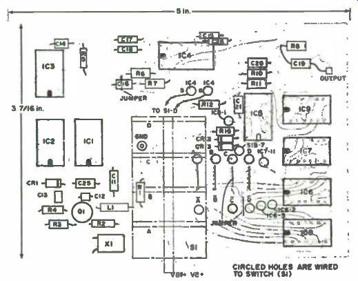
Fig. 8-10. Parts layout.
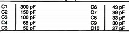
Table 8-3. Tuning Capacitors.
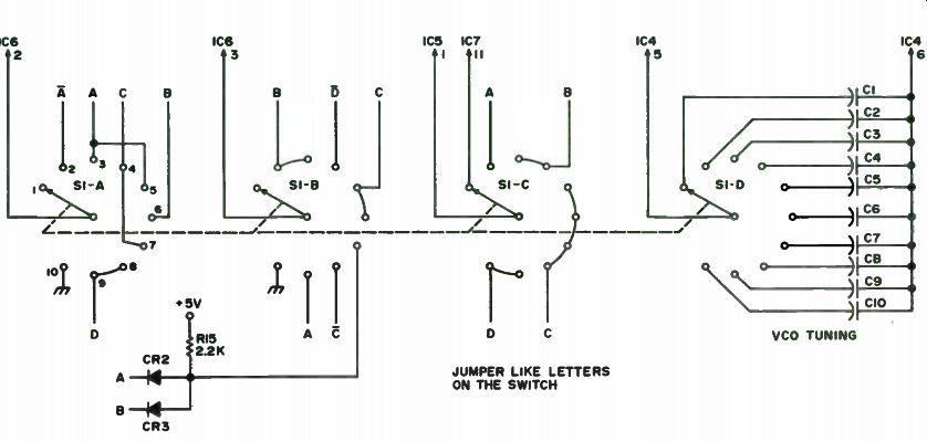
Fig. 8-8. Programmable counter switching and VCO tuning diagram. C1-C10-Elmenco
DM10 or DM15 silver micas; CR2, CR3-1N118 (germanium).
Fig. 8-9. PC board.
------------------

Table 8-4. Miscellaneous Parts List.
3 1/2- x 5" copper clad board
Aluminum box
Line cord On-off switch Connector Misc. hardware ICs available from: B&F Enterprises, 119 Foster St., Peabody MA 01960; or Solid State Systems, P.O. Box 773, Columbia MO 65201.
--------------------------
(Model FS-200B for $ 19.95) less controls, switch, connectors and cabinet.
Buy one of the fully-assembled units, hook it up to a 9-volt battery and you'll be pleasantly surprised to discover that it works just great. It provides strong markers at practically any desired internal frequency well into the VHF region (over 100 MHz for some units). The unit we used easily calibrated against WWV by adjustment of a trimmer capacitor on the PC board. You could also calibrate and cross-check against a frequency counter of known accuracy. If you calibrate by zero-beating against WWV, it's best to use the highest frequency receivable so that you would be using a high-order harmonic of the basic oscillator in the calibrator, for highest accuracy. One point to remember is that, as you approach zero-beat, the audio beat note becomes lower and lower, so it may be difficult to detect true zero-beat. Try using the receiver's S-meter. It will usually try to track the swing through zero-beat and can generally be relied on to get down to within a few cycles accuracy.
The fact that the FS-200 can produce markers down to 25 Hz suggests other uses for it-perhaps as an oscilloscope calibrator/timebase and audio signal generator. By interrupting its supply voltage, it could even be used as a code practice oscillator.
As fine an instrument as the FS-200 is, it does present a mint problem.
It is another little convenience gadget for the workshop that needs another 9-volt transistor radio battery. Though they're inexpensive and easily avail able at Radio Shack, each time one poops out, you have to open up the cabinet and replace the battery. This is a slightly inconvenient task when done repeatedly. The addition of the FS-200 brings into focus the need for a small, cheap power supply, providing a source of multiple low-voltage outputs. The FS-200 could provide the piggyback vehicle for it, along with some simple interface circuitry for the calibrator. The only modifications required on the calibrator are mounting two rear-apron miniature phone jacks (external power and key), running leads to the battery clips and mounting an RCA phono jack on the rear apron for rf output (wired in parallel with the front-panel BNC jack). Be sure to remove the PC board while drilling to prevent possible damage to the components.
The circuit in Fig. 8-12 is what evolved when this was tried. Mounted in a 3- 1/4" x 2-3/16" x 4" minibox (Radio Shack #270-251 or equivalent) and connected to the FS-200 by a short length of cable, it provides interface ...
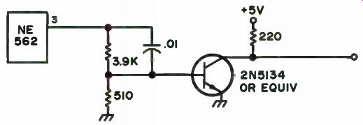
Fig. 8-11. Output circuit to drive logic. ( Note: Circuit from Signetics Handbook.)
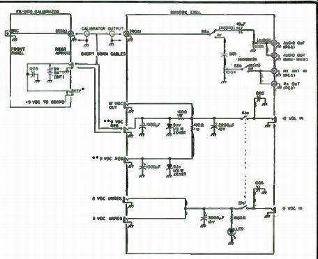
Fig. 8-12. Interface diagram. Additional 6-, 9-, and 12-volt outputs may be
added as desired. All values are nominal. You may have to experiment with zener
and LED dropping resistors for best performance. * Insulated from the chassis
(mounted on the plastic rear apron of the FS-200). "Low current drain
(20-30 mA). Use high- wattage zeners and dropping resistors for higher current
capacity. Use separate zener circuitry for each regulated device.
...circuitry for the calibrator and a means of low-voltage power distribution.
The circuit provides direct receiver rf output coupling for the FS-200, a small antenna or auxiliary rf output and adjustable rf and audio outputs. Also provided are non-regulated 6- and 12-volt outputs, as well as regulated 9-volt outputs to power various and sundry gadgets. Regulated power for the FS-200 .is simply routed back to it through a short length of cable. Using a closed-circuit jack on the FS-200 rear apron allows internal 9-volt battery operation when external power is removed. An LED provides power-on indication for the interface/distribution box. Wiring follows conventional point-to-point practice.
The power source used for the unit is simple. Locate two junk box AC adapters (battery eliminators). One provides about 12v DC (no load) at 300 mA and the other supplies about 6.2v DC at 300 mA. The 12-, 9- and 6-volt circuits are kept separate to keep interaction down and regulation simple.
Zener diodes in the 9-volt circuit provide a small degree of voltage regulation. Though the output of the battery eliminator (AC adapter) doesn't have enough real current reserve for good regulation under heavy loads, it can easily power most of the small low-current accessory devices which require four penlight cells or 9-volt transistor radio batteries as power sources. A 9-volt adapter can be used if a 12-volt unit can't be located, with the dropping resistor values changed accordingly. Voltage regulation would, of course, be minimal. No attempt was made to regulate the 6-volt circuit, though this could be done if necessary for your purposes.
In any case, ensure that the adapters used are not cheapies having a direct connection to the AC line, which would present shock and grounding-out problems. Also, most adapters are not adequately filtered to provide good DC output. High-value electrolytics ( 1000-3000 uF) across the supply lines will do much to filter out any trace of hum or ripple.
Various types of connectors can be used on the piggyback box for audio, rf and power connections, whichever meet your needs. RCA-type phono jacks can be used for rf (routing the receiver coax antenna lead through the unit for signal injection), RCA-type phono jacks and miniature Amphenol-type mike connectors can be used for audio and miniature phone jacks for dc power input and output.
Note that if you use the calibrator with a transceiver, you will have to provide some means of switching it out of the circuit on transmit to prevent transmitter output from damaging the unit. If your transceiver has an external receiving antenna input, you can usually route the output there- check your transceiver's schematic first! Suggested application notes and circuitry are furnished by the manufacturer.
For code practice, it's easiest to simply run the rf output directly into the receiver. The FS-200 is acting, in effect, as a mini CW oscillator. The receiver doesn't even need a bfo. By playing around with the range and multiplier switches, you can come up with MCW (modulated CW). Try it for code practice-it really works.
Don't try to use the piggyback supply for IC circuits requiring good regulation under heavy load; it isn't designed for such use. But, for the multitude of simple projects and gadgets (audio filters, compressors, preamps, signal generators, etc.) requiring but a nominal source of low voltage DC, it fills a real need at a minimum investment, not tying up an expensive, heavy-duty regulated DC supply. If you don't own an FS-200, try building the power distribution box anyway. You'll find it will interface well with other less versatile calibrators, signal and marker generators, and audio generators and the power supply will indeed come in very handy when the battery in your speech compressor or keyer fails!
Super Standard Goes Right Down to 1 Hz
With the proliferation of subbands and interference-obscured net frequencies, the use of an accurate secondary frequency standard is both good operating procedure and also helps fill legal requirements for frequency measurement capability under FCC regulations. In addition, such a standard can be used as a timebase or signal injector to test digital logic circuits.
The WA7VVC frequency standard was designed to be a low cost answer to the need for a good secondary frequency standard. It generates marker signals of 1000, 500, 100, 50, 25, 10, 5 and 1 kHz and 100, 10 and 1 Hz. With harmonics usable well beyond 30 MHz, markers are available to denote subband edges, align receiver dials, find net frequencies and measure the frequency of unknown signals. Should your latest logic circuit not perk properly, two TTL level outputs are available as substitute clocks or signal injectors.
Short term accuracy is approximately 1 part in 106. The unit is easily aligned to WWV with a short wave receiver. An attenuator is included to permit matching signal strengths with the received signal so that a zero beat can be easily and accurately identified. Only one trimmer need be adjusted to align the standard.
With the standard still attached to the receiver and providing an audible measure of its accuracy, a counter or other TTL-compatible device may be attached to either TTL output and that device's accuracy checked.
A frequency burst mode is provided to allow identification of the standard's markers in a crowded receiver passband. Enabling the burst turns the output on and off 10 times per second, resulting in an easily recognized "beep-beep-beep." This burst is also available on one TTL output.
An external DC input makes operation in the field possible. Nine-15 volts at 250 milliamps is all that you will need to have an accurate standard available for Field Day. This is cheap insurance against FCC out-of-band citations.
Circuit Description. The active devices in the frequency generation chain are 7400 series TTL. They are readily available, easy to use, inexpensive and capable of the fast rise times necessary for high level high frequency harmonics.
The oscillator shown in the schematic of Fig. 8-13 uses a 7404 hex inverter, Al, with a 200 kHz crystal as the feedback element for frequency stability. This circuit provides clean output. The circuit will work with either a 2000 kHz crystal or a 1000 kHz crystal. In fact, you can eliminate one 7474 package by using a 1000 kHz oscillator.
Frequency division is accomplished by 7474 dual type D flip-flops A2, A9 and A10, and 7490 decade counters A3-A6, All and A12 wired for division by 10. The 7474s are used as toggle flip-flops by connecting Q to the data input. Preset and clear are not used and are tied high through 1.8k resistors. The 7490s are ripple counters and are prone to spikes and level changes in their output. Proper bypassing of all ICs is necessary to prevent these devices from putting spikes on the power buses. The . 1 uF bypass capacitors are not superfluous-use one at each IC. The various frequency outputs are selected by a rotary switch and fed to A8c, one section of a 7400 quad gate. The selected frequency can either be passed without charge or gated with the 10 Hz output of A7, an NE555 astable oscillator, producing an easily identified frequency burst at the output terminals.
The NE555 timer A14 is used as an astable oscillator whose output is a train of 24 millisecond low-going pulses with a period of 0.81 seconds. Al5a inverts this to a train of positive-going pulses. A15b and A16a gate the pulse train under control of the STEP push-button switch.
On each low-going pulse edge at pin 14, the 7493 binary counter A17 increments by one. Al6b forces a reset on a counter output of 1011, permitting outputs from 0000 through 1010 to select the 11 frequencies of the standard.
The binary output of A17 causes the 74150 multiplexer A19 to select a signal from its inputs to be fed to the standard's output buffers. A18, a 74154 binary to one of 16 decoder, enables the corresponding LED. To change frequencies on the standard, depress the STEP push button. The standard will step through its 11 outputs, one every . 8 seconds until the button is released. When the desired frequency is reached, as indicated by its LED, you have three-quarters of a second in which to release the button before the standard steps again.
Because of the additional current required by the electronic switch, the 2200 uF filter capacitor should be changed to 4700 uF if this circuit is added.
The remaining gates of the 7400 are used as output buffers. The two used for TTL outputs will drive 10 TTL loads apiece. One of these gates buffers the 1000 kHz output of A2a and makes it available at a BNC jack on the rear panel. The other takes the output of A8c, which is controlled by the frequency selector and the BURST switch, and makes it available at a BNC jack.
The output to a receiver is from A8b through a 100 pF capacitor and a 500 ohm pot used as a signal level attenuator. Connection of the pot as shown on the schematic prevents the receiver sensitivity from being affected by the attenuator setting.
The power supply uses the ubiquitous LM309K +5 volt regulator.
Since the circuit draws only 250 milliamperes, the project case can be used as the heat sink. Dissipation of the 309 is only 0.7 watts.
Substitution for the surplus 7 volt power transformer used is easy. Use a 12.6 volt center-tapped filament transformer in the configuration of Fig. 8-14.
In order to use the unit in the field, provision is made for an external DC input. The . 01 uF capacitor removes stray rf from the power lines and the series diodes prevent damage from polarity reversal. Two diodes were used ...
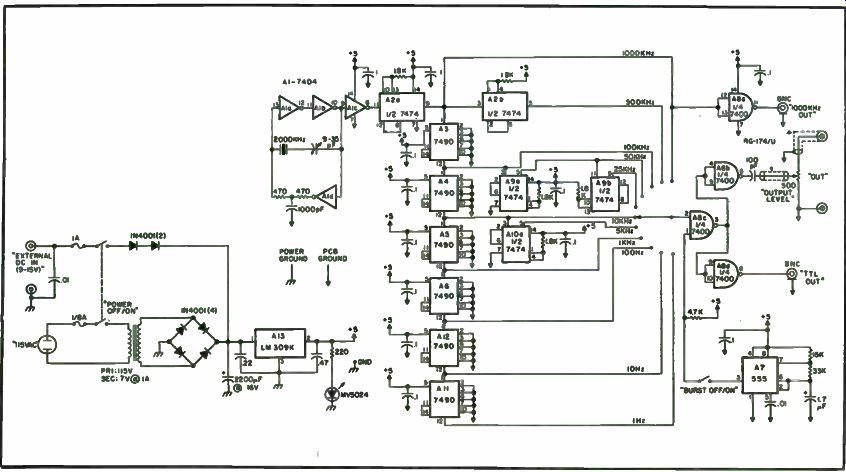
Fig. 8-13. Schematic.
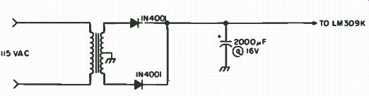
Fig. 8- 14. Configuration for a filament transformer.
... because the 14.5 volts of a car battery under charge come perilously close to the filter capacitor's 16 volt rating. With the two diodes shown, applicable DC input voltage is 9-15 volts. With the appropriate filter capacitor voltage rating and a single diode, voltages in the range of 8 to 25 can be used.
Do not leave out the 0.22 uF bypass capacitor on the 309 input. It prevents oscillation of the device should a remote battery be used as a power source.
Construction. Because of the high speed switching characteristics of TTL and the high frequency harmonic content of the output waveforms, each IC is a transmitter and each interconnecting wire is an antenna. A thoughtful layout and careful construction are important to minimize un wanted radiation.
Switching transients appearing on the Vcc and ground lines can add unwanted noise to the output. Use a prototyping board with Vcc and ground planes to minimize glitches. A printed circuit board would be even better. If you wish to build the circuit with wire wrap sockets on vector-board, use bus wire for the power leads to the sockets. An effective technique is to interleave Vcc and ground bus wires for each row of IC sockets, with a row not containing more than six ICs.
Bus wire should also be used to connect the board directly to the 309.
Do not invite problems by grounding the board to the chassis. Connect the chassis to the 309 case, the board to the 309 case and the rectifier ground to the 309 case. This prevents the board ground from rising above the power ground and developing noise problems.
Asynchronous TTL devices such as the 7490 generate plenty of switching transients. Put a . 1 uF bypass capacitor between Vcc and ground at each device socket and another at the power input to the board. Bypass the 309 input and output as shown in the schematic to prevent spikes and oscillation.
The leads connecting the frequency divider ICs and the selector switch make excellent antennas, so shield the output from the board to the attenuator pot and from the pot to the output terminals with RG-174 coax to reduce unwanted pickup. Long unshielded leads will reduce the effective control range of the pot.
Mechanical stability will be reflected in electrical stability. Rigidly mount the crystal and trimmer capacitor close to the 7404 oscillator.
You Already Have an Atomic Frequency Standard
Whenever a frequency standard is brought up, usually the discussion turns to the National Bureau of Standard's shortwave broadcasts on station WWV, but using these transmissions at any distance from Fort Collins, Colorado, where the transmitter is located, is difficult when reception is poor.
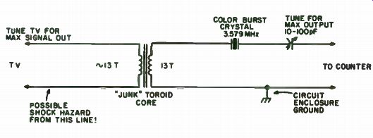
Fig. 8-15. Color burst isolator and filter.
If you service CB radio equipment, commercial transmitters or radio gear, an accurate means of measuring frequency is essential. If you are an experimenter who has a frequency counter, perhaps you have either not calibrated it or let its calibration slip because you did not realize that an atomic frequency standard was as close as your color television receiver.
For some time now, NBS has been pushing the color TV burst frequency as a method of frequency dissemination, and once you use the system it will become apparent that it is both very accurate and inexpensive to implement.
The basic idea is that all three major TV networks use atomic oscillators to produce the 3.5795455454 MHz color subcarrier frequency which is used to code and decode the color information in the video signal. This subcarrier frequency, or more exactly a piece of it, is broadcast with the video which is then used by the color receiver to regenerate a continuous carrier in the set for decoding purposes. The continuous frequency generated by the set is locked in frequency and phase to the transmitted piece of carrier or color burst as it is called, which thus produces an exact replica of the output of the network's atomic oscillator. While there may be minor phase shifts due to path length changes from network switching, the frequency stability is basically that of the generating source.
Thus, your access to an atomic frequency standard involves two simple steps:
• Bringing the color burst frequency out of a TV and into your counter.
• Waiting for a network program to come on. Local stations use crystal oscillators which, while good, can be a couple of Hertz off frequency.
The tapping of the color burst frequency in your set may take a little imagination, since each set is a little different. Receiver subcarrier regeneration systems fall into two broad categories: phase locked oscillators and ringing tuned circuits. To get into the right territory, look for the color burst crystal on your set's schematic diagram. Examine the circuit around the crystal to determine which type of system you have. If the crystal is an oscillator, then you have the phased locked type and it is the output of that oscillator that you want to bring out of the set. If the signal seems to pass through the crystal as a filter, then you have the ringing system and it is the output of the amplifier stage following the crystal that you should tap. Do not try to take an output from the crystal itself, as this can lower its Q and could stop oscillations altogether.
In either case, look for a good low impedance output point. Careful probing about with a scope should turn up a nice clean waveform you can use. Some set schematics have waveform pictures that can often be helpful clues. A word of caution is needed to remind you that many portable receivers have no power transformer, so the chassis could be 115 volts hot! For this reason, use the circuit of Fig. 8-15 on your portable set. The toroid transformer isolates the set from the line. Include an additional color burst crystal to peak the waveform into nice clean sine wave and filter noise pulses. This circuit easily drives your counter. You may find that the tint, color or fine tuning controls on the set, as well as the trimmer on the isolator circuit, may need to be used to peak your output waveform.
The tap-off circuitry tends to affect color reception, so you may want to have a jack to remove your output circuit when you are not using the set for calibration purposes. An alternative is to only use the set as a frequency standard, especially if it lost one of its colors in the picture tube and was deemed not worth fixing. This is a very common occurrence. Since you really need only one color to tell if a program is network (you could probably get by with just sound), so long as the color burst section is working, you have your atomic standard.
Your home-built counter can have a timebase that can be set as long as 100 seconds. This means that the counter, when adjusted, can read color burst frequencies to . 01 Hz (or has an accuracy of . 1 Hz at CB frequencies or 0.4 Hz at 2 meters). If your counter reads with a 1 second timebase, you can only set it to 1 Hz at color burst frequencies, giving you an accuracy of 10 Hz at CB and 40 Hz at 2 meters when calibrated.
To calibrate the timebase oscillator on your counter, just feed the color burst frequency from the set into your counter and read its frequency with your maximum resolution setting. Now adjust your timebase oscillator trimmer until the display reads 3, 579,545.35 Hz. The reason for the . 35 Hz rather than the ideal . 45 Hz is that all network frequencies are slightly offset due to a change in the international frequency standard after the oscillators were installed. You should measure with a good clear stretch of network programming and look out for commercials that may be local. Greatest timebase accuracy is attained when your counter is left on continuously. In any event you should remember to allow a good warm-up period before calibration.
While the network frequencies have been 3,579,545.35 Hz for years, if you really want to stay on top of this situation you can subscribe to the NBS monthly time and frequency services bulletin, which lists the exact offsets for each network on a week basis. It is free on request, the only cost being a questionnaire they ask you to fill out about once a year asking which NBS service you use ( WWV, TV, data, etc.), how often and why (ham radio, CB service, hobby, etc.). With the bulletin, great accuracy can easily be achieved. Those people with clock and frequency standard hobbies have found the TV system to be a tremendous boon to obtaining synchronization of secondary standards with little effort or expense. For extreme precision, a beat-frequency method can be used (but it is more complicated than the direct count method described here). If you choose to leave your counter running continuously, you may wish to consider dividing your timebase to 50 Hz and building one of the numerous clock kits available today. Set your digital clock chip to run from 50 Hz and feed the timebase signal into the circuit where it previously was connected to the power transformer. (The 60 Hz line is still used for power.) Instant Counter Calibration Using Your TV Set It's rather unfortunate that the development of affordable frequency counters paralleled the recent rapid growth of two meter FM, because the serious FMer should have (or have access to) a reasonably accurate frequency counter for netting the crystals in his or her rig. The luxury of being talked-in on the larger systems has passed. For the moment, let's suppose that you have your own frequency counter. How does one go about accurately calibrating (or at least verifying the calibration of) the little gem? As already mentioned, you are probably a little surprised at what a handy little frequency reference a TV set can be when tuned to a network station.
All four TV networks, NBC, CBS, ABC and PBS, presently use rubidium frequency standards to generate their color burst, horizontal sync pulses and vertical sync pulses. Some local stations also use rubidium standards locked to the network with which they are affiliated, but unless you are sure, you can't count on it. These rubidium standards are traceable to NBS (National Bureau of Standards) of WWV fame, inasmuch as the networks are monitored by NBS and offsets are published periodically.
At this point, it should be explained exactly what a rubidium frequency standard is. Rubidium 87 is a metallic element whose automic resonance is 6834.6826 MHz. This natural atomic resonance of rubidium 87 is very stable and not easily upset by external factors (particularly when properly shielded and operating in a temperature-controlled cavity).The rubidium unit influences control on a crystal oscillator, which then adopts the same order of stability as the rubidium reference. The crystal oscillator feeds a frequency synthesizer that contains outputs of 5.0 MHz and 3.579554 MHz (color burst frequency). The long-term (one year) stability of commercially available rubidium standards is ± 5 + 10-11, and the short-term (one second) stability is ±1 + 10-11. These figures improve even more when correlated to NBS offsets.
As stated earlier, the TV station uses the 3, 579, 545.4 Hz color burst signal as a reference for its sync generators, which then derive the familiar horizontal and vertical sync signals used to lock the sweep oscillators in the home TV receiver.
Here's how you can take advantage of those highly accurate signals that are beaming around us, all of 18 plus hours a day. The easiest way is to pick up the horizontal sync signal, which is in abundance inside the cabinet of a TV receiver due to its use for the derivation of the high voltage that's needed to run the picture tube. This high voltage spike can be found anywhere around the flyback transformer or the picture tube yoke (which is a safer area to work in). If the set has a wooden or plastic cabinet and your counter is sensitive enough, you may find enough signal to lock on even outside of the cabinet (try the picture tube screen for openers). Note that there is no need to connect either lead from the counter directly to the TV receiver. In fact, unless the TV set is equipped with a power transformer, it would be disastrous to do so (especially if the counter is grounded, which it should be)! Some of the newer portable TV sets have no power line isolation transformers and use bridge rectifier circuits for AC to DC conversion, with the result that even reversing the AC line cord won't place the DC common at ground potential (it's always hot). This situation makes it impossible to hook up externally grounded test equipment to these sets unless an external isolation transformer is used. The preceding was mentioned only to protect the innocent. During a network color broadcast, the horizontal scanning frequency will be 15,734.265 Hz, which can be read on the Heath IB-1103 (if you happen to have one) by simply placing a well insulated lead from the counter over the deflection yoke on the neck of the picture tube. You'll notice, if your counter will read below 1 Hz, that the "265" will vary between counter sampling periods because you're not phase locked to the signal.
It should hit ". 265" occasionally. On most counters, if you're within a couple of cycles of 15,734 Hz, you're in good shape. Incidentally, you can use a black and white TV instead of a color set because its horizontal oscillator is locked to the color standards (H and V sync pulses) as well. Just be sure you are tuned to a network color program. Most network color mobile units now have rubidium standards on board, with the possible exception of the small news mini-cam units. Even in-the-field sporting events will provide accurate sync signals. One more thing: Don't be in a hurry. Give yourself enough time to average the reading over a 10 or 15 minute period. This will give the clocking oscillator in the counter time to stabilize after adjustment, and also will permit you to observe the medium term stability of your counter. Whether or not you actually watch the program on the TV screen is strictly up to you.
There are some inherent errors in the system just described, such as distortion in the microwave relays used for cross-country TV signals, transmission and multi-path distortions within the local ether and distortions that take place within the TV receiver itself, but these are phase and not ...
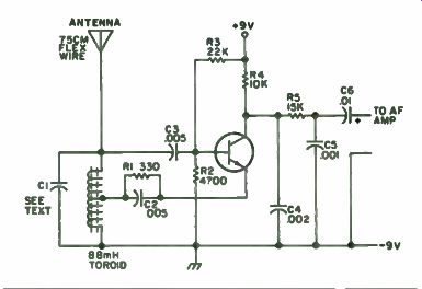
Fig. 8-16. Simple receiver.
... frequency distortions. As long as you're not trying to read to three places below one cycle (Hertz), don't worry about them.
There you have it-no digging into the circuitry, handy at most times of the day and night, available throughout the country and very accurate.
A 15.75 kHz Oscillator Simple TV Test Unit
This is to describe a device of considerable value to the many experimenters that service TVs either in the shop or at home. It is simply a regenerative receiver set on 15.75 kHz, the TV horizontal oscillator frequency.
With it the horizontal oscillator frequency can be set correctly without a signal and the adjustment make in seconds without any doubt as to whether to increase or decrease the oscillator frequency. Many of us have spent valuable time in the shop blindly turning the slug in and out without the slightest idea where it should be for the correct frequency. If the oscillator is not working, there will be no signal regardless of adjustment. Adjustment of the horizontal oscillator in the usual manner only brings the frequency near enough that the sync pulse can lock it in step and thus is no assurance that in the free-running state it is on frequency.
This receiver may be built into any small case such as that from a defunct transistor radio. Its variable condenser, audio amplifier and speaker may also be used if good. It may be made small enough to carry in a shirt pocket on house calls.
It is a simple project (Fig. 8-16). To conserve space and avoid hand capacity effect, an 88 mH toroid coil was used rather than a regular horizontal oscillator coil which would have required some shielding.
This circuit using the collector at ground potential for rf was chosen to simplify the audio takeoff. R5C5 provides additional filtering to keep rf out of the audio output. Use the audio amplifier in the original case, if convenient. If you must build your own, a small IC is suggested for compactness.
A regenerative receiver is most sensitive when not oscillating at full strength, so it is a good idea to use variable resistors to determine the best values for reliable but not excessive feedback, replacing them with the nearest fixed small resistors. It is safe to assume that at least 100 types, requiring different bias resistors, etc., may do well here.
C1 is made up of one or more fixed mica condensers in parallel with a small variable condenser or mica compression trimmer; the latter is definitely second choice. The total capacity required should be around 0.0018. Marked values are seldom correct. Temperature sensitive condensers are to be avoided for tuning. Silver micas are preferred. The temporary use of an external variable condenser of considerable capacity will expedite finding the proper value and frequency.
With this receiver's antenna near the horizontal area of an operating TV, listen for the 15.75 kHz signal when you are sure the receiver is oscillating. When zero-beat is obtained, with final tuning condensers in place in the final assembly, no further adjustment is required and it is ready for use.
With no signal or antenna on the TV to be serviced and with front panel control, if any, set at midrange, adjust the horizontal slug for zero-beat with the receiver and you are finished with that part of the job-no guesswork! If the sync doesn't take control, then that is a different problem, and there is no need to twiddle with the horizontal oscillator.
--
Next: Signal Generators