| Home | Audio mag. | Stereo
Review mag. | High
Fidelity mag. |
AE/AA mag.
|
|
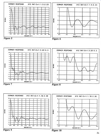
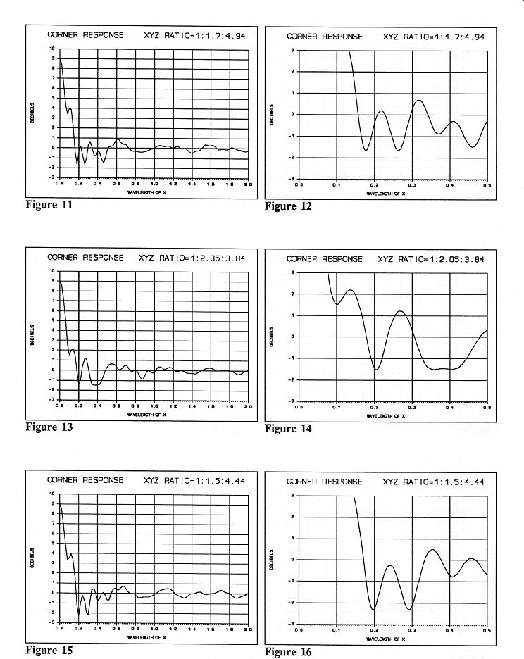
By William Rasnake; President, Pacific Northwest Audio Society, Senior Product Planner, John Fluke Mfg. Co., Inc.  For the first time, the complex interaction of corner proximity and room shape is mathematically massaged to yield the theoretically and/or practically best speaker placement for smooth and extended low-frequency response in any room. For years I have found the ideal positions in a room for speakers by using high-volume white noise and hours of experimentation. I carefully positioned both speakers until there were no longer any peaks or dips in the response as I walked around the general listening area. This procedure drove the wife, daughter, and cats out of the house until they were sure the torture was over. Experimentation is still a good procedure for checking midrange and treble smoothness, but this article is about using math and science to position speakers in your room for the best bass response. This is especially useful if the room has not been built yet! Some of the positions you find through this method may not be the best for the couch, the spouse, or the house, but I hope you will find at least one option that will work both musically and aesthetically. Many fine articles, papers, and books about room resonances and corner positioning of speakers have been written. The ones I used most are listed in the references. My premise is that you can dramatically flatten the frequency response of a woofer by combining two theories: placing the woofer so it is in a favorable position with respect to the nearest corner, as well as in a good position to minimize resonances caused by the shape of the room. Like many good things in life, the answer isn't as easy as telling you to place the speakers 1/3 of the way down a wall. This is a start, however, and with a little effort and a simple calculator you will be able to improve bass clarity further and even lower frequency response. Room dimensions and room resonances. First, let's take a look at the effect room resonances have on a speaker's bass response. If you were to position yourself in every corner of the room and draw a straight line to every other corner in the room, you would end up with all the possible resonant lengths of the room. You would also have many different straight lines! Every sound wavelength and harmonic that matches one of these lengths creates a resonant standing wave. The standing waves add to or subtract from the speaker output, depending on the speaker's position and the listener's position in the room. These standing waves are created by three resonant modes. Axial resonant modes are created by the distance between facing parallel walls or floor and ceiling. Tangential resonant modes are created by the distances represented by the diagonals on the floor, walls, and ceiling. Oblique resonant modes are created by the distance through air from a corner to another corner. Since the axial resonant modes are twice as powerful as any other mode, let's examine how to avoid their effects. The primary (fundamental) axial resonance occurs when sound has a wavelength equal to twice the distance between two facing walls (or floor and ceiling). To find the frequency, we must know the speed of sound and the distance between the two walls. At sea level the speed of sound is about 1127 feet per second (an international com promise between 1126.3 ft/s @ 20° C and 1128.4 ft/s @ 70° F). The primary (fundamental) axial resonant frequency is calculated by dividing 1127 by 2 times the distance between the walls (in feet). For example, a room that is 8' 10" high by 19' 4" wide by 21' 3" long (typical of a remodeled garage for a displaced audiophile and also the size of the newly built studio of The Audio Critic) has primary resonances of 63.8 Hz, 29.1 Hz, and 26.5 Hz (1127/2x8.83, 1127/2x19.33, and 1127/2x21.25). The dark line in Figure 1 represents the effect this has on the sound pressure level at locations between the walls. Halfway across the room (50% in Figure 1) there is a deep null. The lighter lines represent the harmonics. At the second harmonic of this frequency there is a peak at 50% and a deep null at 25%. Each additional harmonic causes new peaks and nulls to occur, some at the same location of the lower-frequency peaks and nulls. The room basically becomes the inside of an organ pipe for low frequencies. It also means that a single-channel subwoofer should never be in the center of a wall. Figure 2 plots only the minimum and maximum sound pressure levels versus position, for the primary (fundamental) resonance and each harmonic up to the sixth. As you vary the frequency, the sound pressure varies the least when you are 33.3% (1/3) of the way across the room. The next best positions are 20% or 40% (1/5 or 2/5) of the way across the room. The next best positions are 14.3%, 28.6%, or 42.9% (1/7, 2/7, or 3/7) of the way across the room. Note also that in Figure 2 there is more margin for error at the 33.3% (1/3) and 20% (1/5) positions. There is less margin for error at the 40% (2/5) position. In other words, if you divide the distance between the walls by odd numbers, you will locate the points of least sound pressure variation; and the smaller the odd number, the smaller the variation. The corollary is also true: if you divide the distance between the walls by even numbers, you locate the points of maximum sound pressure variation; and the smaller the even number, the greater the variation (1/2, 1/4, 1/8, 3/8). The 28.6% (2/7) position between walls may be a good position for planar speakers because planar speakers are velocity devices instead of pressure devices, and the sound pressure never quite reaches maximum in this position. If you are a "golden ratio" fan, this position (2/7 and 5/7) also divides the two speaker positions and the room walls into sections where the next number in the series is the sum of the preceding two (2/7 to the first wall, 3/7 between speakers, and 5/7 to the second wall; 5/7 equals the sum of 2/7 and 3/7). At higher frequencies-above 500 to 1000 Hz-the peaks and nulls become so closely located to one another that the texture of the walls, sound absorption materials, furniture, and furnishings become the dominant factor in the character of the sound. Table 1 will be used to calculate the height positions in your room that have minimum resonance. The results are the best heights from the floor for your speaker's woofer. A room with an 8-foot (96") ceiling would have 13.7", 19.2", 27.4", 32", 38.4", and 41.1" as minimum resonance positions. My choices are 19.2" (1/5), 27.4" (2/7), or 32" (1/3). If your speaker is floor-standing, the manufacturer has already made the choice for you. Table 3 will be used to calculate the minimum resonant positions for the floor plan of your room. The intersections create a map of low-resonance positions for one corner of your room. If your room is L-shaped, or is not a rectangle, use the rectangular end nearest the speakers. Bass response for irregular rooms can be improved by properly positioning the woofer with respect to the nearest corner. Finding an acceptable woofer position with respect to the nearest corner is also the next step. We all know that moving the speakers changes the bass response for better or worse depending on the kind of music. A major factor is that the reflections from the floor and walls at the nearest corner cause destructive interference with the speaker's direct output. This interference adds to or subtracts from the direct output, depending on both the frequency and the position of the speaker. The result is more total power for some frequencies and less power for others. The goal is to keep the bass power response as flat as possible and get boost from the corner only at very low frequencies, where most speakers need help. The relevant mathematical relationships. You don't have to understand this paragraph and the equation below to enjoy the results. They are presented for the mathematically inclined. The total radiated power (at a given frequency) from a speaker near a corner is estimated by calculating the radiation resistance of the speaker in the corner compared to the radiation resistance in free space. The following equation is used to estimate the power: 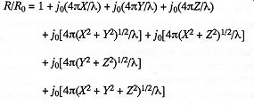 where R = radiation resistance R0= free-space radiation resistance J0(a) = (sin a)/a pi = 3.141592653589... λ = lambda, the wavelength of sound X,Y,Z = the perpendicular distances to the nearest walls and floor forming the corner The graphs and tables use X as the shortest distance, set A to 1 wavelength, and increment X, Y, and Z versus A. The only variable the user has control over is the perpendicular distance from the center of the woofer to the walls (and to the floor if the speaker is not floor-standing). So, you get to experiment with moving the speaker closer to or farther away from the back and side walls. Figure 3 illustrates the effect on power output versus wavelength (which we will convert to frequency) of positioning a speaker exactly the same distance from the floor, back wall, and side wall (a ratio of 1:1:1). When this distance is about 0.28 of the sound's wavelength, there will be a deep null. The wavelength scale on the graph can be converted to frequency once we know the distance of X. For example, 24" is one wavelength of 564 Hz. If the center of a speaker's woofer is 24" high and 24" from both the back and side walls, we would have a deep null at about 158 Hz (0.28x564 Hz). If the walls are rigid (like concrete) and reflect all the sound, the null will be about 11.4 dB from the speaker's free air response. This is the worst-case position with respect to the corner. Don't think of concrete walls as a detriment, though; they are actually more predictable and will be a benefit in the better solutions that follow. Figure 4 illustrates power output variations if we choose the best ratio of distances I have found. That ratio is 1:1.67:2.46 instead of 1:1:1. Note that the power output variation is less than +1 dB down to a wavelength of 0.12, where you start getting bass boost from the corner. The bass boost is +3 dB at 0.1 wavelength and will theoretically increase up to +9 dB. A practical maximum bass boost is +6 dB to +8 dB because the walls will not be perfectly rig id. If we use the same speaker with the 24" high woofer, the three distances would be 24", 40.1", and 59.0". At this position from the corner, we would get a +3 dB boost at 0.1 wavelength on the scale, equivalent to 56 Hz (0.1x564 Hz). The graphs in Figures 5 through 16 illustrate the effect on power output with different ratios of distances from the woofer to the three reflecting surfaces (walls and floor). Each ratio solution has two graphs, one that extends to 2 wavelengths of X for an overall view, and one to 0.5 wavelength to help you see where +3 dB boost occurs. All the "Corner Response" graphs are scaled to the wavelength of X, the distance to the floor (or to the nearest wall if the woofer is closer to a wall than the floor). The best ratio solutions were found with a program developed to calculate the peak-to-peak change in power output after the power dropped below 0 dB. The exact solutions, including the peak-to-peak variation and +3 dB wavelength, are also part of Table 2. Table 4 converts the 1.0 wavelength of X to frequency once you know the distance of X for your speaker. Another benefit of this procedure is that the acoustical loading of the speaker into the room is more uniform. This provides better control of the speaker's excursions and a more uniform load to the amplifier. The result is more power output before distortion. How to proceed to optimize your own setup. Now comes the part where you find the best positions in your room for your speakers. Start by measuring the width, length, and height of your room to the nearest inch. Use the hard surfaces as references (bass does not "see" carpet, padding, drapes, etc.). Next measure the height of the center of the speaker's woofer. If there is more than one woofer or the woofer is a panel speaker, use the center of the woofer array or panel. Take out your calculator and fill in every blank location in Table 1, Table 2 (both A and B), and Table 3. Do this even though some of the calculations are not practical for your speakers or room. It will give you a better feel for the solutions and make compromise selections of good locations easier. If your speaker is not floor-standing, choose a height for your woofer from Table 1 before completing Table 2 or 3. Examine the pairs of distances calculated in Table 2. Are there any pair combinations from Table 2 close to the pair combinations on the Table 3 map? The dimensions calculated in Table 2 are interchangeable between back or side walls. For every good match between a Table 2 (corner) solution and a Table 3 (room) solution, mark the intersection on the Table 3 map. Also use the Table 3 map to find a good listening position. The best listening positions are 1/3, 1/5, 2/5, or 2/7 of the distance between the wall behind the listener and the wall behind the speakers. Measure from the wall behind the listener for normal rooms. Measure from the wall behind the speakers for long rooms. Select a listening position that is also 0.87 to 1.4 times the distance between the centers of the two speakers. Position your speaker at one of the final solutions you marked on the map in Table 3. Use a position that works for your room and listening position. The front center of the woofer should be at the calculated intersection. This is a reasonable compromise for path length differences around the back of the speaker compared to the side or towards the floor. If the woofer faces the rear, measure the distance to the back wall from the apex of the woofer. Simplify the positioning of the second speaker by measuring the distance from the back wall to the back of the first speaker and the distance from the side wall to the side of the first speaker. If you toe in your speakers, measure the distance from both back corners of the first speaker to the back wall. I personally select a speaker and listening position, aim the center of the first speaker at the listener's ear on that side, and then measure from the speaker's rear corners to the walls. Use these three measurements to position the second speaker. If none of the pair combinations in Table 2 match intersections on the Table 3 map, mark the intersections on the Table 3 map that are close to pair combinations in Table 2. Calculate a compromise position by splitting the difference between the Table 2 and Table 3 solutions. The Audio Critic's room and a new speaker arrival will be a good example to experiment with. The speaker is a floor-standing model with the center of the woofer 13" from the floor. The following pair combination solutions are calculated using Table 2A: 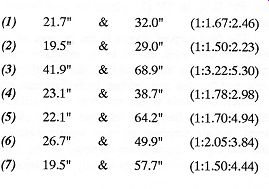 The room is 255" long and 232" wide. The following minimum room resonance positions are calculated using Table 3: Longer Wall (255") 1/11 1/9 1/7 1/5 2/9 2/7 232% 283" 364" 510". 56.7" 72.9" Shorter Wall (232") 33.1" 46.4" 66.3" The shorter wall is the back wall in this room. The woofer of this particular speaker is close to the floor; this will cause some of the above solutions to be impractical. Also, the strong low-bass response of this speaker suggests that it be placed at one of the more distant solutions. The first of the Table 2 solutions above (21.7" & 32.0") is nearly a perfect match to the room but too close to the corner. The bass boost will occur at too high a frequency. The second solution (19.5" & 29.0") is even closer to the corner. The third solution (41.9" & 68.9") is close to the 66.3" position along the shorter wall but somewhat off the 36.4" position along the longer wall. The fourth solution (23.1" & 38.7") is a poor match along the shorter wall and probably too close to the corner. The fifth solution (22.1" & 64.2") is near 23.2" along the longer wall and 66.3" along the shorter wall but too close to the shorter (back) wall. The sixth solution (26.7" & 49.9") is near 28.3" along the longer wall and 46.4" along the shorter wall but probably still too close to the corner. The seventh solution is too close. The best probable choice is the third solution with a compromise. The first and sixth solutions are possible alternates. The modified third solution is a compromise between 41.9" & 36.4" from the back wall and 68.9" & 66.3" from the side wall. Use 39" from the back wall and 68" from the side wall. The spread between 41.9" and 36.4" (about +7% from 39") is an example of the maximum compromise you should make. The large size of this room is more forgiving and will allow more compromise. Use Table 4 to find the frequency with a wavelength of 13" (the X distance for this example). It is 1040 Hz. Use Table 2A to estimate the +3 dB frequency for this solution (the third solution). The frequency is approximately 52 Hz (0.05%1040 Hz). In this example, the room will start to boost the bass at about 52 Hz. Also use Table 3 to find a good listening position. This room is 255" long. Good listening positions are 102" (2/5), 85" (1/3), or 73" (2/7) from the wall behind the listener. The final step of course is the purpose of suffering through all this work. Listen to the results in your room. Especially listen to acoustical bass, acoustical organ, large drums, and familiar male voices. Individual bass notes will be clearer, and male voices will lose their artificial resonances. The bass frequency response will be closer to the natural free-air response of your woofer system. Large peaks and dips in the midbass response will be absent, and a surprising amount of energy at truly low frequencies will be present. The improvements, of course, will depend on how good the speaker positions were to begin with. Editor's Note Bill Rasnake and a partner have formed a small avocational company specializing in listening-room acoustics. If you send them $29.00, they will provide you with a computer optimization and printout for your particular speakers and room. For additional speakers in the same room they charge 315.00. Carefully measure the dimensions of your room and the height of your woofer-or woofers, if there is also a subwoofer-from the floor, and send the data along with the appropriate fee to Clear Image Audio, 10020A Main Street, Suite 388, Bellevue, WA 98004. Include any constraints or special requests. We are told that room design and consultation at your site are also available. This is for your information only and does not imply a recommendation of the company by The Audio Critic; all we know is that the method presented in this article is valid and worked exactly as claimed in our room. The only caveat we would add is that the best possible speaker location for bass is not necessarily the best for imaging, high-frequency dispersion and reflections, etc. Further "difference splitting" may be consequently be required. At the very least, however, Bill Rasnake's method takes the guesswork out of speaker placement for bass optimization. References: 1. K. O. Ballagh, "Optimum Loudspeaker Placement Near Reflecting Planes," Journal of the Audio Engineering Society, 31 (Dec. 1983), 931-935. 2. Floyd E. Toole, "The Listening Room, Audio's Forgotten Component," Audio Scene Canada, Mar. and Apr. 1976. 3. F. Alton Everest, Handbook for Sound Engineers, ed. Glen Ballou (Howard W. Sams & Co., 1987). 4. Donald E. Hall, Basic Acoustics (Harper & Row Publishers, 1987). 5. Philip M. Morse and K. Uno Ingard, Theoretical Acoustics (McGraw Hill, 1968, Princeton University Press edition, 1986). 6. James Moir, F.I.E.E., "Interactions of Loudspeakers and Rooms," Wireless World, Jun. 1977. 7. Roy F. Allison, "The Influence of Room Boundaries on Loudspeaker Power Output," Journal of the Audio Engineering Society, 22 (Jun. 1974), 314-320. 8. Robert Berkovitz, "Sound and Your Listening Room," Stereo Review, Aug. 1983. 9. Peter Mitchell, "Loudspeaker Placement," Stereo Review, Aug. 1980. 10. Roy Allison, "The Delicate Question of Speaker Placement," Stereo Review, Aug. 1975. 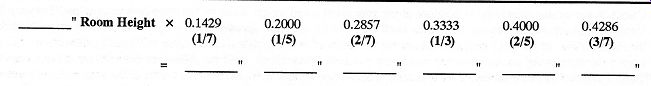 Table 1: Best Choices from Center of Woofer to Floor 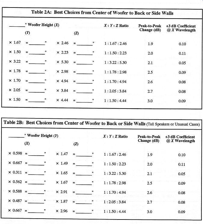 Table 2A: Best Choices from Center of Woofer to Back or Side Walls Table 2B: Best Choices from Center of Woofer to Back or Side Walls (Tall Speakers or Unusual Cases) 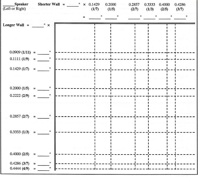 Table 3: Floor Plan for Position of One Speaker Calculate the minimum resonance positions along your shorter and longer walls on the floor-plan map below. The map is for the left speaker if the shorter wall is the back wall and for the right speaker if the longer wall is the back wall. Mark the intersections on the floor plan that also match the pairs of corner-position calculations in Table 2 (within about 5%). Locate the front center of the woofer at one of the practical intersections. Split the difference between the calculations in Table 2 and the intersections below if you cannot find the prefect match. Maker sure the center of the woofer is not located at 1/2, 1/4, 1/8, or 3/8 of the distance between walls. Use the mirror-image location for the other speaker. 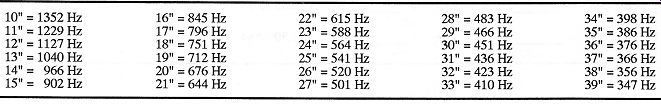 Table 4: One Full Wavelength Conversion to Frequency (for sound @ 1127 ft/sec) ------------- 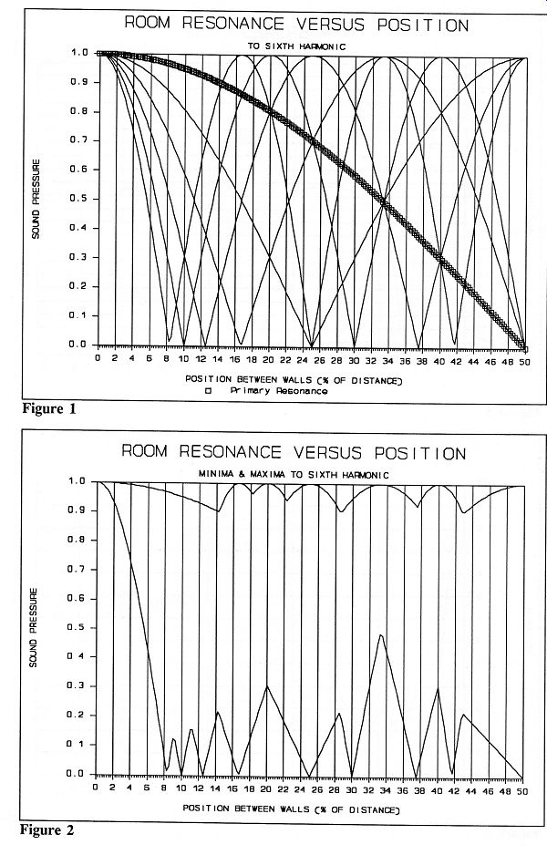 Figure 1 ; Figure 2 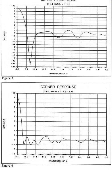 Figure 3 - Figure 4
Figure 5- Figure 10
Figure 11 -Figure 16 ------- [adapted from TAC 13] --------- Also see: Seven Loudspeaker Systems (If They Are All So Accurate, How Come They All Sound Different?): Audio Concepts "Sapphire" with "Saturn"; Carver "Amazing Loudspeaker" (Platinum II Edition); JBL L40t3 ; Precise "Monitor 10" ; Quad ESL-63 USA Monitor ; Snell Type C/II ; Waveform [TAC 14] Various audio and high-fidelity magazines Top of page |
|
| Home | Audio Magazine | Stereo Review magazine | AE/AA mag. |