12. Transformer Design and Construction
For low frequencies, power and communications transformers may be either of two types-core or shell. The iron core of the core-type transformer is rectangular in shape and has a clear area in the center. It may be constructed of L-shaped or I-shaped inter leaved laminations, as illustrated in Fig. 7. Most transformers, especially those of the power variety, are wound so that half the primary is on one leg and half on the other leg. The same is done with the secondary winding. It is not uncommon to find other winding schemes in audio and other communications transformers.
For instance, the primary and secondary are sometimes wound on the same leg of the frame, leaving the other leg free. In some cases, all of the primary winding is placed on one leg and all of the secondary on the other. [The first method minimizes leakage inductance (see Section 17) and is therefore preferred when this is a significant factor.]
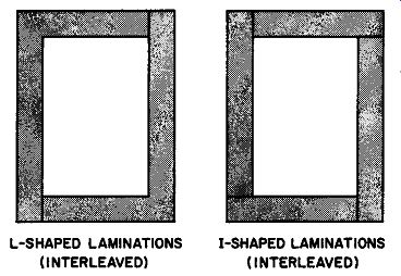
Fig.
7. Core-type transformer laminations may be interleaved L's or I's. L-SHAPED
LAMINATIONS (INTERLEAVED) ; I-SHAPED LAMINATIONS (INTERLEAVED)
A shell-type core is built up of interleaved or butt-jointed sections shaped like an E or an I. Both the primary and secondary coils are wound on the center leg of the core, with the low voltage winding going on first, i.e., nearest the core leg. Shell construction has the advantage of providing larger area flux paths that help confine the magnetic fields within the core. Most small power and audio transformers use shell-type design. Figure 8 shows the positions of the windings in a voltage step-up transformer.
Laminations are stamped from thin sheet metal. When the stamping process is completed, each lamination has a fine burr along its edges that prevents the sections from lying on one another in perfect mechanical contact. Thus, as a result of the burr making the effective cross-sectional area of the core somewhat smaller than its actual cross-sectional area, there is a loss of physical space.
Since the space loss is a function of the method of interleaving, the transformer manufacturer is concerned with what he calls the stacking factor (the ratio of the effective, working cross-sectional area, to the actual or measured cross-sectional area of the core) . When laminations from the same stamping die are used, a butt-jointed core without interleaving gives a greater stacking factor, and is the preferred method. A larger stacking factor means that less iron is necessary to achieve a given working cross-sectional area. For example, alternate interleaving-accomplished by alternate reversal of E's and I's-gives a stacking factor of approximately 0.87, while butt-jointing without reversal of E's and I's yields a stacking factor of better than 0.94. On the other hand, interleaving produces a core with greater mechanical strength and somewhat better magnetic-conductive characteristics. The choice of core construction depends on the exact specifications of the transformer and the particular manufacturing facilities available.

Fig. 8. Shell-type core.
It was shown that the counter-emf induced in the primary winding of a transformer (e1) is virtually the same as the input genera tor voltage (eu). The smaller the resistance of the primary winding, the more closely does e; approach the value of eu. In a perfect transformer, the relationship:
e1 = eg (13)
is true. From Equations (12) and (13), we may write:
- NP def> (14)
eg – 10^8 X dt
where NP = primary turns
The same flux variations which affect the primary coil to which eu is applied also act upon the secondary winding. The voltage induced in the secondary winding, as a result of the magnetizing current flowing in the primary, is then: N. def>
e. = 10^8 X dt (15)
where N, = secondary turns
Dividing Equation (14) by Equation (15): eg _ NP
e. - N. (16)
Equation (16) has been derived on the basis of two assumptions.
First, that the transformer is perfect (its primary has zero resistance and the flux linkage between the two windings is 100%) and, second, that the transformer is unloaded. Since neither of these conditions is ever true in practice, Equation (16) must be considered an ideal law, subject to corrections that are implied by the actual working conditions.
Example 2. If the secondary voltage of a perfect, unloaded transformer is 12,000 volts and the primary-to-secondary turns ratio is 1:1000, what is the applied primary voltage?
Solution. Solving Equation (16) for eu and substituting: e = 12,000 X _I_ = 12 volts g 1,000
14. Efficiency and Coil Currents
Upon connecting a load to the secondary winding, the emf induced in this winding sets up a load current. Since power will now be consumed in the secondary circuit, Lenz's Law dictates that the direction of the magnetic field resulting from the secondary current must oppose the initial field from the primary. The opposing flux therefore reduces the total flux to an extent determined by the amount of secondary current flowing. Reduced flux reacts upon the primary winding by causing the counter-emf developed therein to diminish, thereby permitting a greater primary current to flow. In this way, the input to a transformer accommodates itself to match the demands made upon the output by the load. A transformer is an excellent example of an electrical device that demonstrates the wisdom of the law of conservation of energy.
A good transformer has little affect upon the power factor of the circuit to which it is connected, although small deviations from the unity power factor take on importance in special calculations.
Assuming unity power factor, the efficiency of a transformer may be defined as:
% efficiency = e•!• x 100 ( 17)
eglg
where e8, i., e9 , and ifl denote the corresponding rms values of secondary and primary voltages, and currents.
Normally, the efficiencies of transformers run very high, with values of the order of 95% to 99% common. If the efficiency of a transformer is assumed to be 100%, then the denominator and numerator of the fraction in Equation (17) may be equated: egii: = e.i. (18)
or eg i.

(19)
e. i,
Substituting the turns ratio as given m Equation (16) for the voltage ratio, we have:

i. _ Nr ii: N. (20)
Equation 20 demonstrates that the primary and secondary currents, in and i., respectively, are inversely proportional to the number of turns on their corresponding coils.
An important point. The secondary current, i8 , is governed by the secondary voltage and the load across which this voltage is applied. Here, the secondary winding is considered to be a simple generator that obeys Ohm's Law in accordance with fundamental a-c principles. The primary current, however, is determined by the applied potential, e9 , and the impedance of the primary coil.
As shown previously, the impedance of the primary is in turn con trolled by the counter-flux produced by the secondary current.
Equation (20) is merely a mathematical relationship derived from prior identities that arose from physical concepts. Equation (20) does not explain why a given primary-to-secondary current ratio exists. As discussed below, this current ratio is a function of fluxes and counter-fluxes that are not explicitly expressed in the equation.
Example 3. What is the power output of a transformer having an efficiency of 85%, if it draws 8 amperes from a 120 volt line?
Solution. In terms of the facts given and required, Equation (17) may be restated as:
% efficiency = power output eJs
Solving the literal equation: power output = (% elf) x (eJs)
100 X 100 so that
= 85 X 8 X 120
= 816 volt-amperes 100
(21)
... and since unity power factor is assumed (unless otherwise stated): power output = 816 watts
15. Coupling and Mutual Inductance
When two coils are placed near each other in a way such that a change of current in one causes a voltage to appear across the other, they are said to possess mutual inductance. Like self-inductance, mutual inductance is measured in henries. Two coils are said to have a mutual inductance of I henry, if a current changing at the rate of I ampere/second in one of the coils causes a voltage of l volt to appear across the terminals of the other coil. From this definition, it is readily apparent that the relationship between the induced voltage (e,), the rate of change of current in one coil (dir,/dt), and the mutual inductance (M) is given by:

(22)
Self-inductance in a single coil is given by a similar equation:
di e1 = L dt
in which e, = the induced voltage, L is the self-inductance of the coil in henries, and di/dt is the rate of change of the current in amperes/second.
When two coils having self-inductances (or just inductances) of L1 and L,, respectively, are brought into a physical relationship such that the mutual inductance between them is M, it can be shown by differential calculus that the maximum mutual inductance is limited by the values of self-inductance as given in Equation (24).

maximum M = ~ (24)

Fig. 9. Series 1 connected primary and secondary transformer windings.
M can reach its maximum value only if the flux linkage from coil 1 to coil 2 is perfect (every line coming from coil 1 passes through coil 2). If the flux linkage is not perfect, M will be less than its maximum possible value. The ratio of the actual amount of mutual inductance to the maximum possible value is a useful one, because it expresses the extent to which two inductances are coupled, independently of the magnitudes of the inductances concerned.
This ratio, symbolized by k is known as the coefficient of coupling and is defined by:

~ (25)
The coefficient of coupling is dimensionless, since both the numerator and denominator of Equation (24) are given in the same units. In a perfect transformer (i.e., where there is 100% flux linkage) , k = I, since the mutual inductance would be maxi mum and hence equal to the square root of L 1L 1 • This condition is sometimes referred to as unity coupling. Transformer windings are considered closely coupled if k is greater than 0.5. If k = 0.01 or less, the coils are said to be loosely coupled.
16. Experimental Determination of M and k
The primary and secondary windings of an iron-core transformer may be connected in series in one of two ways (see Fig. 9). For one method of connection, the flux generated by the primary current will be in the same direction as the flux generated by the secondary current in the common core. This situation is known as series-aiding. In the other connection, the two fluxes will oppose each other in the core. This is called series-opposing. Because a mutual inductance exists between the coils, the total inductance of the series combination will not be merely the sum of the two inductances but will include the effect of M, as follows: L1
+ L2
+ 2M for series-aiding L1
+ L2
- 2M for series-opposing (26)

(27)
These relationships provide a convenient method for experimentally determining the value of M. The windings are first connected in series-aiding and the total inductance, L1a, is measured.
Next, they are connected in series-opposing and L 10 is measured.
(Inductance measurement may be obtained by using an inductance bridge of the correct range, or by using Ohm's Law and determining the impedance, and from this, obtaining the inductance with the help of the measured resistance of the current path, using standard a-c methods of solution.) If Equation (27) is subtracted from Equation (26), we obtain:
Lta - Lto = 4M or (28)
The mutual inductance is equal to the difference between the inductances in series-aiding and series-opposing divided by 4.
Once M is determined, k is readily obtained from Equation (25). Example 4, A transformer has a primary with an inductance of 2 henries and a secondary with an inductance of 6 henries. In series-aiding, the total inductance is 14 henries. In series-opposing, the total inductance is 2 henries. Find the mutual inductance between windings and the coefficient of coupling.
Solution. The quantities given are L1
= 2 henries, L2
= 6 henries, Lta = 14 henries, and Lto = 2 henries.
Thus
= 14
2
= 3 henries 4 and M k----
- ~ 3
= Vf2" = 0.866
17. Leakage Inductance
Even in the best transformers, not all the magnetic flux produced in one winding links with the other coil. This "leakage" flux causes an emf of self-induction and occasions what is known as leakage inductance in each coil. Leakage inductance behaves exactly the same way as an equivalent amount of ordinary inductance inserted in series with the winding of the transformer. Thus, it has a definite reactance and can produce a voltage drop which increases with increasing current.
As the load on the secondary increases, the voltage drop due to leakage inductance increases, and consequently causes the secondary terminal voltage to drop. Leakage inductance is the principal cause preventing the primary-to-secondary voltage ratio from equaling the primary-to-secondary turns ratio. In a reasonably well-designed power transformer (leakage inductance is kept low), the secondary voltage at full load should not drop more than about 8% below its no-load value. Since leakage reactance is also a function of frequency (Xr, = 2 pi fL), the effect of leakage inductance in audio transformers is serious.
A good approximation of the total leakage inductance of a transformer may be obtained by measuring the primary inductance (with the secondary winding short-circuited) and the secondary inductance (with the primary winding short-circuited). The nearer k is to unity, the more closely will this approximation approach the true value of the total leakage inductance. If Lmp is the measured primary inductance, Lap is the actual or true primary inductance. Lm, is the measured secondary inductance, La, is the actual secondary inductance, and k is the coefficient of coupling, and analysis shows that the quantities are related as follows:
Lmp = 2 (1 - k) Lap with secondary short-circuited (29)
Lm• = 2 (1 - k) L.. with primary short-circuited (30)
Both equations yield the expected result, if k is unity: with the linkage perfect, there is no measurable primary or secondary inductance even though the true inductances of these windings may be high. As k drops in value, the measured inductance of each winding increases. This means that the leakage inductance also in creases. To keep leakage inductance low and to maintain the best possible transformer performance, k must be maintained as close to unity as possible.
The amount of leakage inductance present is almost independent of the core material; but, it depends upon the manner in which the coils are wound, their dimensions, their separation, etc. By using wide, very flat windings with little separation, leakage inductance is generally minimized. Interleaving the primary and secondary windings minimizes leakage inductance further.
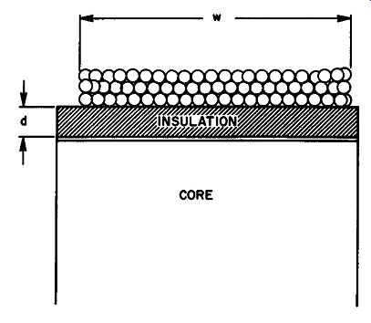
Fig. 10. Some of the factors that control the distributed capacitance between
a transformer coil and its core.
18. Distributed Capacitance
The upper frequency response of a transformer is largely dependent upon the distributed capacitances that exist between the two ends of a given winding, between adjacent windings, and between a given winding and the core. Distributed capacitance is most often determined by direct measurement; but, it is valuable to know the factors that determine it and how they may be controlled.
Many of the equations found in transformer design literature are empirically obtained. They represent approximations that, as the number of layers in a given winding is increased, agree more and more closely with the actual measured figures. (See Fig. 10.) Calculation of distributed capacitances is usually begun by measuring as precisely as possible the capacitance between the core and winding. (The ends of the winding are tied together for this measurement.) The equation obtained empirically from many such measurements taken is:

C _ 0.2251 wK a - d (31)
in which C,. = capacitance between core and winding, l = mean length of a single turn in inches, w = width of the layer in inches, K = dielectric constant of the insulation, and d = thickness of total insulation between winding and core. Equation (31) demonstrates that the distributed capacitance from winding to core is directly proportional to the length of a turn (average) , the width of the winding (average), the dielectric constant of the insulation, and varies inversely with the total insulation thickness.
Some circuits call for grounding one end of the winding to the chassis, which automatically grounds one end to the core. For this condition, the distributed capacitance between the core and winding decreases and Cb= ~a (32)

where Cb is the distributed capacitance in µ.µ.f.
The shunt capacitance of a winding is one of the more important considerations in transformer design. It is defined as the capacitance that exists between the ends of a multi-layer coil. This capacitance, Cc, is given by:
C _ 0.301 w K (NL - 1)
C - dNL2 (33)
where NL = the number of layers in the coil. The distributed capacitances of a transformer change somewhat when the center is grounded (center-tapped). (Exact formulas for these capacitances are empirical and may be found in any transformer designer's handbook.)
19. Transformer Sizes
The actual volume or physical size of a transformer depends on such factors as the type of core material used, the type of cooling, the permissible temperature rise for which the transformer has been designed, and the thickness of insulation material required for the potentials used. The above considerations are based on the load requirements of the transformer. However, the load requirement cannot always be considered merely the volt-ampere rating of the secondary winding. Certain usages require special handling. For example, when a center-tapped transformer works into a full-wave rectifier circuit and is followed by a choke-input filter, considerable current distortion is produced in the transformer secondary winding, hence in the primary winding also. In this case, it may be shown experimentally and mathematically that for each 100 watts of load power consumed, the average transformer dissipation rating should be about 140 watts. Thus, this type of application demands a transformer of an appreciably higher wattage rating than others in which this rectifier-filter system is used.
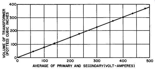
Fig. 11. Empirical size curve obtained by averaging physical sizes for several
hundred transformers.
On the other hand, when a transformer is called upon to supply power for conventional a-c loads, its physical size is generally based upon empirical data gathered over years of engineering experimentation. In Fig. 11, an empirical curve is presented for an average transformer designed for usage in the 60 Hz range, where cooling takes place only by normal convection and the allowable tempera ture rise is 40° C.
20. Maximum Operating Temperatures
Normal transformer engineering practice is to design for a specified temperature rise. Permissible temperature rise, in turn, is a function of the kind and quality of the insulation on the coil wires, and the insulation used to separate winding layers from each other, and from the core.
Organic materials, such as cotton, silk, paper, and varnished paper, when exposed to temperatures above certain well-defined limits tend to become dry and brittle. If the temperature continues to be high, charring results, with a further loss of mechanical strength. Overloads or vibrations under these circumstances may then produce costly breakdowns. Inorganic insulation tends to soften and melt at high temperatures. To enable the transformer engineer to intelligently choose the insulation for a given tempera ture rise, the American Institute of Electrical Engineers (A.I.E.E.) has promulgated a classification which establishes five grades of insulation, on the basis of maximum operating temperature. A summary of this classification is given in Table I. The actual temperature rise of a transformer is usually measured by determining the change in its winding resistance. A 4% resistance rise very closely equals a l0°C increase in temperature.
==========
TABLE 1
Class Max. Temp. Materials
0 A 90°C Cotton, silk, paper, and similar organic insulators without impregnation or immersion.
105°C
(1) Impregnated or immersed organic insulation listed for class 0.
(2) Molded and laminated materials with cellulose, phenolic resins, and other resins.
(3) Films and sheets of cellulose acetate
(4) Enamels or varnishes B 130°C Mica, asbestos, fiberglass, and similar inorganic materials that use organic binders.
H 180°C Same as class B, except with silicon binders.
C over 180°C All mica, porcelain, glass, quartz, and similar in organic materials.
============
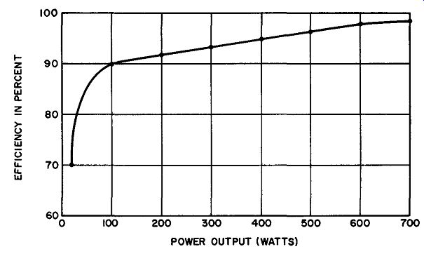
Fig. 12. Relative efficiencies of small and large power transformers, operating
at 60 Hz into a resistive load with a maximum temperature rise of .40°C, cooled
only by convection.
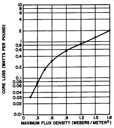
Fig. 13. Variation of core 10 ohm with increasing flux density for 60 Hz core
material of medium-grade silicon steel.
21. Efficiencies of Small and Large Power Transformers
For a specified maximum temperature increase, it has been found that a small power transformer can tolerate lower efficiency operating conditions better than a large one. Since maximum efficiency is obtained when the load is so adjusted that the core losses are equal to the copper losses, small power transformers intended for use at line frequencies below 100 Hz may be designed with somewhat smaller cores than would be anticipated by considering relative power demand. In this way, less core material is used.
Therefore, the efficiency of the power transformer decreases but this need not cause the temperature rise to exceed the limit set by the insulation. It is this economy in design which results in the smaller efficiencies found in low-power transformers. The comparative efficiencies of small and large transformers obtained by averaging several hundred transformers of different manufacturers are shown in the curve of Fig. 12.
22. Core Materials
Although extremely high permeability materials are now avail· able, most commercial power transformer manufacturers still em ploy annealed steel laminations with a 2% to 5% silicon content. This material possess relatively high permeability even at high flux densities. Therefore, when compared to more expensive core materials, silicon steel represents a substantial economy, since it is inexpensive and avoids excessive core losses. (Figure 13 illustrates how the core losses in a typical medium-grade silicon steel rise with increasing flux density.) Audio transformers require core materials that have high permeability at low flux densities. This need is satisfied by alloys such as mu-metal (nickel, iron, manganese, and copper) and permalloy (nickel, iron manganese, and molybdenum) . The many grades of core materials available often make selection difficult, since there are usually several solutions to any given problem in transformer design. Generally, cost and size are the prime factors. Occasionally the choice must be based on ease of assembly, ease of mounting the completed transformer, or on the fact that only one particular core material will provide the desired electrical performance.
23. QUIZ
1. What are the differences between a shell-type and a core-type transformer?
2. What secondary voltage might be expected from a perfect, unloaded transformer if 6.3 volts is applied to a primary having 350 turns, and if the secondary contains 3500 turns?
3. Explain how the secondary load controls the amount of primary current that flows in a power transformer.
4. What is the efficiency of a 100 volt-ampere transformer if 50 volts applied to its primary causes a primary current of 2.09 amperes to flow?
5. What is meant by the equation e1 = M (di/dt)?
6. Find the coefficient of coupling if the mutual inductance between two 8-henry coils is 7.6 henries.
7. Explain fully the process and measurements that must be taken to make an experimental determination of the mutual inductance between two coupled iron-core coils.
8. What is meant by leakage inductance?
9. Explain why keeping k close to unity results in small leakage inductance.
10. Describe in detail how the distributed capacitance of a transformer winding is determined experimentally.
11. Discuss the various types of insulation used by modem transformer manufacturers from the point of view of transformers' maximum permissible operating temperatures.